EP0073028A2 - Kraftfahrzeugmotor mit einem Klopfsensor - Google Patents
Kraftfahrzeugmotor mit einem Klopfsensor Download PDFInfo
- Publication number
- EP0073028A2 EP0073028A2 EP82107599A EP82107599A EP0073028A2 EP 0073028 A2 EP0073028 A2 EP 0073028A2 EP 82107599 A EP82107599 A EP 82107599A EP 82107599 A EP82107599 A EP 82107599A EP 0073028 A2 EP0073028 A2 EP 0073028A2
- Authority
- EP
- European Patent Office
- Prior art keywords
- engine
- bearing
- knock
- cylinder block
- internal combustion
- Prior art date
- Legal status (The legal status is an assumption and is not a legal conclusion. Google has not performed a legal analysis and makes no representation as to the accuracy of the status listed.)
- Withdrawn
Links
Images
Classifications
-
- F—MECHANICAL ENGINEERING; LIGHTING; HEATING; WEAPONS; BLASTING
- F02—COMBUSTION ENGINES; HOT-GAS OR COMBUSTION-PRODUCT ENGINE PLANTS
- F02F—CYLINDERS, PISTONS OR CASINGS, FOR COMBUSTION ENGINES; ARRANGEMENTS OF SEALINGS IN COMBUSTION ENGINES
- F02F7/00—Casings, e.g. crankcases
- F02F7/0065—Shape of casings for other machine parts and purposes, e.g. utilisation purposes, safety
- F02F7/008—Sound insulation
-
- F—MECHANICAL ENGINEERING; LIGHTING; HEATING; WEAPONS; BLASTING
- F02—COMBUSTION ENGINES; HOT-GAS OR COMBUSTION-PRODUCT ENGINE PLANTS
- F02B—INTERNAL-COMBUSTION PISTON ENGINES; COMBUSTION ENGINES IN GENERAL
- F02B77/00—Component parts, details or accessories, not otherwise provided for
- F02B77/08—Safety, indicating, or supervising devices
- F02B77/085—Safety, indicating, or supervising devices with sensors measuring combustion processes, e.g. knocking, pressure, ionization, combustion flame
-
- G—PHYSICS
- G01—MEASURING; TESTING
- G01L—MEASURING FORCE, STRESS, TORQUE, WORK, MECHANICAL POWER, MECHANICAL EFFICIENCY, OR FLUID PRESSURE
- G01L23/00—Devices or apparatus for measuring or indicating or recording rapid changes, such as oscillations, in the pressure of steam, gas, or liquid; Indicators for determining work or energy of steam, internal-combustion, or other fluid-pressure engines from the condition of the working fluid
- G01L23/22—Devices or apparatus for measuring or indicating or recording rapid changes, such as oscillations, in the pressure of steam, gas, or liquid; Indicators for determining work or energy of steam, internal-combustion, or other fluid-pressure engines from the condition of the working fluid for detecting or indicating knocks in internal-combustion engines; Units comprising pressure-sensitive members combined with ignitors for firing internal-combustion engines
- G01L23/221—Devices or apparatus for measuring or indicating or recording rapid changes, such as oscillations, in the pressure of steam, gas, or liquid; Indicators for determining work or energy of steam, internal-combustion, or other fluid-pressure engines from the condition of the working fluid for detecting or indicating knocks in internal-combustion engines; Units comprising pressure-sensitive members combined with ignitors for firing internal-combustion engines for detecting or indicating knocks in internal combustion engines
-
- F—MECHANICAL ENGINEERING; LIGHTING; HEATING; WEAPONS; BLASTING
- F02—COMBUSTION ENGINES; HOT-GAS OR COMBUSTION-PRODUCT ENGINE PLANTS
- F02F—CYLINDERS, PISTONS OR CASINGS, FOR COMBUSTION ENGINES; ARRANGEMENTS OF SEALINGS IN COMBUSTION ENGINES
- F02F7/00—Casings, e.g. crankcases
- F02F7/0043—Arrangements of mechanical drive elements
- F02F7/0053—Crankshaft bearings fitted in the crankcase
- F02F2007/0056—Crankshaft bearings fitted in the crankcase using bearing beams, i.e. bearings interconnected by a beam or multiple beams
Definitions
- This invention relates, in general, to an improvement in an automotive internal combustion engine, and more particularly to an installation location of an engine knock sensor for detecting engine knock developed in engine cylinders in order to effectively control engine operating conditions such as spark timing of the engine.
- engine knock sensors for detecting engine knock developed in engine cylinders, they are usually located at the outer wall of a cylinder block.
- the thus located knock sensors cannot effectively detect the engine knock with a high precision because vibration due to engine knock in the engine cylinders tends to be damped during its transmission through the cylinder block. This has rendered impossible a high precision control of engine operation condition in response to the output of the knock sensors.
- An internal combustion engine comprises a cylinder block having at its bottom part with a plurality of main bearings.
- a bearing beam structure is secured to the bottom part of the cylinder block and includes a plurality of main beaming cap sections each of which associates with each main bearing of the cylinder block, and at least a beam section for securely connecting all the bearing cap sections with each other.
- an engine knock sensor for detecting engine knock is located at a part of the bearing beam structure, for example, at a part of one of bearing cap sections.
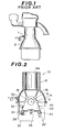
- an engine knock sensor 1 is installed at the outer wall of a water jacket, and the location of the knock sensor 1 is selected at a generally middle section in the direction along which engine cylinders are aligned. Accordingly, the engine knock sensor senses vibration at the surface of a cylinder block or the water jacket outer wall, thereby indirectly detecting engine knock developed in the engine cylinders. The thus detected engine knock is picked up as electric signal and used for controlling the operating conditions of the engine.
- the thus located engine knock sensor has encountered the following shortcomings: In general, when engine knock is generated in the engine cylinders, vibrations of the frequencies around 7 KHz or 13 KHz develop which frequencies are different in accordance with the size of engines. In this connection, such vibrations due to engine knock are considerably damped during their transmission or propagation through the cylinder block of a complicated structure. The degree of such vibration damping becomes higher as the distance of vibration transmission through the cylinder block increases. Therefore, engine knock in the engine cylinder located relatively near the knock sensor 1 can be precisely detected; however, it is difficult to detect precisely engine knock generated within the engine cylinder located relatively far from the knock sensor 1.
- the engine 10 comprises a cylinder block 12 which is, as usual, formed with a plurality of engine cylinders 12a each defining therein a cylinder bore.
- the cylinder block 12 is further formed at its lower part a so-called skirt section 14 which is integral with the engine cylinders 12a and bulged outwardly to define thereinside an upper part of a crankcase.
- a plurality of parallelly disposed main bearing bulkheads 16 are formed integrally with the engine cylinders 12a and with the skirt section 14.
- Each bearing bulkhead 16 is located below the cylinder barrels 12a and integrally connected to a portion between the neighbouring two engine cylinders 12a.
- Each bearing bulkhead 16 is formed with a main bearing 18 for rotatably supporting the journal of a crankshaft whose axis is indicated by the character X.
- a bearing beam structure 20 is securely connected to the bottom part of the cylinder block 12 by means of bolts, and includes a plurality of main bearing cap sections 22.
- Each bearing cap section 22 is rigidly attached to each main bearing bulkhead 16 so that the bearing cap section 22 defines a bore B, in which the crankshaft is disposed, in association with the corresponding main bearing 18 of the bearing bulkhead 16.
- the bearing cap sections 22 are integrally connected by two beam sections or members 24 which are located parallel with each other and extend along the axis X of the crankshaft.
- the two beam sections 24 are positioned at the bottom opposite corners of each bearing cap section 22, respectively.
- the thus formed bearing beam structure 20 functions to suppress fore-and-aft direction movement, due to crankshaft vibration, of the main bearings 18, thereby reducing vibration of cylinder block 12. While the bearing cap sections 22 and the beam sections 24 are shown and described as being integral with each other in this embodiment, it will be understood that they 22, 24 may be independent from each other and fastened to each other by means of bolts or the like.
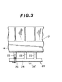
- an engine knock sensor 26 for sensing vibration due to engine knock is so disposed that a part thereof is embedded in one of the bearing cap sections 22.
- the engine knock sensor 26 is fixed in position by means of screw or the like and electrically connected via a lead 28 to a pickup 30 which is secured to the cylinder block skirt section 14.
- the lead 28 is supported by a cramp 32.
- the output of the knock sensor 26 is supplied to a controller (not shown) for controlling engine operating conditions in response to engine knock generated in the engine cylinders 12a.
- the reference numeral 34 denotes an oil pan fixedly attached to the cylinder block skirt section 14.
- the natural frequency of the beam section 24 of the bearing beam structure 20 is set at a value same as a frequency of high frequency vibration due to engine knock, for example, the value in the vicinity of 7 KHz, in which resonance vibration will occur in the beam sections 24 even when engine knock is generated in any engine cylinders, thereby more sensitively detecting engine knock.
- knock sensor 26 has been shown and described as being installed at the bearing cap section 22 of the bearing beam structure 10, it will be understood that it may be installed at the beam section 24 as indicated in phantom and by the reference numeral 26' in Figs. 2 and 3 also by which engine knock can be sensitively detected.
- the bearing cap sections for supporting the crankshaft are securely connected with each other by means of the beam sections, vibration of the main bearings 18 in the fore-and-aft direction can be largely suppressed, thereby effectively reducing cylinder block vibration.
- the engine knock sensor is installed at the beam section of the bearing beam structure or at the bearing cap section directly connected to the beam section, and accordingly the propagation path of high frequency vibration, due to engine knock, from the engine cylinder to the knock sensor is simplified, thereby enabling sensitive detection of engine knock. Therefore, it is possible to largely advance spark timing to an engine knock limit above which engine knock tends to occur, in response to the output of the knock sensor, thereby improving fuel economy, power output, driveability of the engine, while reducing noise emitted from the engine.
Landscapes
- Engineering & Computer Science (AREA)
- Combustion & Propulsion (AREA)
- Chemical & Material Sciences (AREA)
- Mechanical Engineering (AREA)
- General Engineering & Computer Science (AREA)
- Physics & Mathematics (AREA)
- General Physics & Mathematics (AREA)
- Cylinder Crankcases Of Internal Combustion Engines (AREA)
- Combined Controls Of Internal Combustion Engines (AREA)
- Measurement Of Mechanical Vibrations Or Ultrasonic Waves (AREA)
- Shafts, Cranks, Connecting Bars, And Related Bearings (AREA)
- Measuring Fluid Pressure (AREA)
- Electrical Control Of Ignition Timing (AREA)
Applications Claiming Priority (2)
| Application Number | Priority Date | Filing Date | Title |
|---|---|---|---|
| JP56132568A JPS5835232A (ja) | 1981-08-26 | 1981-08-26 | 自動車用エンジンのノツクセンサ取付装置 |
| JP132568/81 | 1981-08-26 |
Publications (2)
| Publication Number | Publication Date |
|---|---|
| EP0073028A2 true EP0073028A2 (de) | 1983-03-02 |
| EP0073028A3 EP0073028A3 (de) | 1983-10-12 |
Family
ID=15084343
Family Applications (1)
| Application Number | Title | Priority Date | Filing Date |
|---|---|---|---|
| EP82107599A Withdrawn EP0073028A3 (de) | 1981-08-26 | 1982-08-19 | Kraftfahrzeugmotor mit einem Klopfsensor |
Country Status (3)
| Country | Link |
|---|---|
| US (1) | US4598681A (de) |
| EP (1) | EP0073028A3 (de) |
| JP (1) | JPS5835232A (de) |
Cited By (1)
| Publication number | Priority date | Publication date | Assignee | Title |
|---|---|---|---|---|
| FR2994214A1 (fr) * | 2012-07-31 | 2014-02-07 | Renault Sa | Moteur a combustion equipe d'un dispositif de detection du cliquetis comportant un capteur de vibrations monte sur la rampe d'injection du moteur |
Families Citing this family (6)
| Publication number | Priority date | Publication date | Assignee | Title |
|---|---|---|---|---|
| JPH02130237A (ja) * | 1988-11-11 | 1990-05-18 | Mitsubishi Electric Corp | 内燃機関のノック抑制装置 |
| US7546198B2 (en) * | 2006-08-03 | 2009-06-09 | Spectral Dynamics, Inc. | Dynamic noise-reduction baselining for real-time spectral analysis of internal combustion engine knock |
| CN105745422B (zh) * | 2013-11-18 | 2019-04-30 | 川崎重工业株式会社 | 发动机 |
| JP6834713B2 (ja) * | 2017-04-05 | 2021-02-24 | スズキ株式会社 | V型エンジンのクランク軸潤滑用オイル通路構造 |
| DE102017113021A1 (de) * | 2017-06-13 | 2018-12-13 | Volkswagen Aktiengesellschaft | Hubkolbenbrennkraftmaschine und Verfahren zum Betreiben einer Hubkolbenbrennkraftmaschine |
| CN110425055A (zh) * | 2019-08-27 | 2019-11-08 | 浙江义利汽车零部件有限公司 | 车辆曲轴箱及车辆 |
Family Cites Families (9)
| Publication number | Priority date | Publication date | Assignee | Title |
|---|---|---|---|---|
| BE472638A (de) * | ||||
| FR472638A (de) * | ||||
| JPS5185947A (de) * | 1975-01-22 | 1976-07-28 | Kunio Nakano | |
| JPS543447U (de) * | 1977-06-13 | 1979-01-10 | ||
| US4153020A (en) * | 1977-07-26 | 1979-05-08 | The United States Of America As Represented By The Administrator Of The United States Environmental Protection Agency | Method and apparatus for spark control of engine knock |
| DE2903788A1 (de) * | 1979-02-01 | 1980-08-14 | Bayerische Motoren Werke Ag | Vorrichtung zur erfassung der bei anomalen verbrennungsvorgaengen in verbrennungsmotoren auftretenden schwingungen |
| DE2952073A1 (de) * | 1979-12-22 | 1981-06-25 | Daimler-Benz Ag, 7000 Stuttgart | Verfahren zur optimierung des arbeitszyklus einer fremdgezuendeten brennkraftmaschine |
| JPS56150356U (de) * | 1980-04-11 | 1981-11-11 | ||
| JPS6320847Y2 (de) * | 1980-04-21 | 1988-06-09 |
-
1981
- 1981-08-26 JP JP56132568A patent/JPS5835232A/ja active Pending
-
1982
- 1982-08-19 EP EP82107599A patent/EP0073028A3/de not_active Withdrawn
-
1985
- 1985-03-22 US US06/714,358 patent/US4598681A/en not_active Expired - Fee Related
Cited By (1)
| Publication number | Priority date | Publication date | Assignee | Title |
|---|---|---|---|---|
| FR2994214A1 (fr) * | 2012-07-31 | 2014-02-07 | Renault Sa | Moteur a combustion equipe d'un dispositif de detection du cliquetis comportant un capteur de vibrations monte sur la rampe d'injection du moteur |
Also Published As
| Publication number | Publication date |
|---|---|
| EP0073028A3 (de) | 1983-10-12 |
| US4598681A (en) | 1986-07-08 |
| JPS5835232A (ja) | 1983-03-01 |
Similar Documents
| Publication | Publication Date | Title |
|---|---|---|
| CA1270166A (en) | Cylinder block structure for internal combustion engine | |
| US4517945A (en) | Engine vibration transmission structure | |
| EP0038560A1 (de) | Brennkraftmaschine | |
| US4598681A (en) | Automotive engine with knock sensor | |
| US4465041A (en) | Cylinder block of internal combustion engine | |
| US4468950A (en) | Engine vibration transmission structure | |
| US6446497B1 (en) | Reciprocating machine with operating parameter sensor | |
| US7475665B2 (en) | Capacitance-based fluid level sensor | |
| US4475508A (en) | Automotive engine cylinder block | |
| US5386723A (en) | Device for detecting faulty firing in an internal-combustion engine | |
| US4903646A (en) | V-type cylinder block of internal combustion engine | |
| EP1482149B1 (de) | Sensoranordnung für eine Brennkraftmaschine | |
| EP1762847B1 (de) | Ölwanne für Brennkraftmaschine | |
| US4474148A (en) | Internal combustion engine with bearing beam structure | |
| EP0057869A2 (de) | Brennkraftmaschine mit Verbindung zum Getriebe | |
| JP2007192823A (ja) | 流体レベルセンサ | |
| JPH0582533B2 (de) | ||
| JP2001193520A (ja) | エンジンのノックセンサ取付構造 | |
| EP0065104B1 (de) | Motor mit innerer Verbrennung mit einer Tragbalkenstruktur | |
| US4805442A (en) | Knocking sensor for internal combustion engine | |
| EP0064457B2 (de) | Zylinderblock für eine Brennkraftmaschine | |
| EP0054246A1 (de) | Brennkraftmaschine mit einem Hauptlager-Rahmen | |
| JPS62101839A (ja) | V型エンジンのノツクセンサ取付構造 | |
| CN207989165U (zh) | 气缸体结构 | |
| JPH0453549Y2 (de) |
Legal Events
| Date | Code | Title | Description |
|---|---|---|---|
| PUAI | Public reference made under article 153(3) epc to a published international application that has entered the european phase |
Free format text: ORIGINAL CODE: 0009012 |
|
| 17P | Request for examination filed |
Effective date: 19820819 |
|
| AK | Designated contracting states |
Designated state(s): DE FR GB |
|
| PUAL | Search report despatched |
Free format text: ORIGINAL CODE: 0009013 |
|
| AK | Designated contracting states |
Designated state(s): DE FR GB |
|
| RAP1 | Party data changed (applicant data changed or rights of an application transferred) |
Owner name: NISSAN MOTOR CO., LTD. |
|
| STAA | Information on the status of an ep patent application or granted ep patent |
Free format text: STATUS: THE APPLICATION HAS BEEN WITHDRAWN |
|
| 18W | Application withdrawn |
Withdrawal date: 19860717 |
|
| RIN1 | Information on inventor provided before grant (corrected) |
Inventor name: HAYASHI, YOSHIMASA |