EP0073044A2 - Batterie d'éléments à combustible avec électrolyte acide - Google Patents
Batterie d'éléments à combustible avec électrolyte acide Download PDFInfo
- Publication number
- EP0073044A2 EP0073044A2 EP82107655A EP82107655A EP0073044A2 EP 0073044 A2 EP0073044 A2 EP 0073044A2 EP 82107655 A EP82107655 A EP 82107655A EP 82107655 A EP82107655 A EP 82107655A EP 0073044 A2 EP0073044 A2 EP 0073044A2
- Authority
- EP
- European Patent Office
- Prior art keywords
- fuel
- electrode
- battery
- oxidant
- chamber
- Prior art date
- Legal status (The legal status is an assumption and is not a legal conclusion. Google has not performed a legal analysis and makes no representation as to the accuracy of the status listed.)
- Granted
Links
- 239000000446 fuel Substances 0.000 title claims abstract description 164
- 239000003792 electrolyte Substances 0.000 title claims abstract description 28
- 230000002378 acidificating effect Effects 0.000 title claims abstract description 16
- 239000007789 gas Substances 0.000 claims abstract description 76
- 239000007800 oxidant agent Substances 0.000 claims abstract description 64
- 230000001590 oxidative effect Effects 0.000 claims abstract description 64
- XLYOFNOQVPJJNP-UHFFFAOYSA-N water Substances O XLYOFNOQVPJJNP-UHFFFAOYSA-N 0.000 claims abstract description 26
- 239000001301 oxygen Substances 0.000 claims abstract description 18
- 229910052760 oxygen Inorganic materials 0.000 claims abstract description 18
- QVGXLLKOCUKJST-UHFFFAOYSA-N atomic oxygen Chemical compound [O] QVGXLLKOCUKJST-UHFFFAOYSA-N 0.000 claims abstract description 17
- 238000006243 chemical reaction Methods 0.000 claims abstract description 14
- 238000000926 separation method Methods 0.000 claims description 25
- 239000007788 liquid Substances 0.000 claims description 19
- 238000007599 discharging Methods 0.000 claims description 13
- CURLTUGMZLYLDI-UHFFFAOYSA-N Carbon dioxide Chemical compound O=C=O CURLTUGMZLYLDI-UHFFFAOYSA-N 0.000 claims description 9
- 238000000034 method Methods 0.000 claims description 9
- 229910002092 carbon dioxide Inorganic materials 0.000 claims description 5
- 239000001569 carbon dioxide Substances 0.000 claims description 4
- 238000003487 electrochemical reaction Methods 0.000 claims description 3
- OKKJLVBELUTLKV-UHFFFAOYSA-N Methanol Chemical compound OC OKKJLVBELUTLKV-UHFFFAOYSA-N 0.000 description 12
- 239000000463 material Substances 0.000 description 7
- 239000000203 mixture Substances 0.000 description 7
- OAKJQQAXSVQMHS-UHFFFAOYSA-N Hydrazine Chemical compound NN OAKJQQAXSVQMHS-UHFFFAOYSA-N 0.000 description 6
- -1 air Chemical compound 0.000 description 6
- OKTJSMMVPCPJKN-UHFFFAOYSA-N Carbon Chemical compound [C] OKTJSMMVPCPJKN-UHFFFAOYSA-N 0.000 description 5
- QAOWNCQODCNURD-UHFFFAOYSA-N Sulfuric acid Chemical compound OS(O)(=O)=O QAOWNCQODCNURD-UHFFFAOYSA-N 0.000 description 4
- 238000010276 construction Methods 0.000 description 4
- 229910052751 metal Inorganic materials 0.000 description 4
- 239000002184 metal Substances 0.000 description 4
- 238000010248 power generation Methods 0.000 description 4
- 230000036647 reaction Effects 0.000 description 4
- WSFSSNUMVMOOMR-UHFFFAOYSA-N Formaldehyde Chemical compound O=C WSFSSNUMVMOOMR-UHFFFAOYSA-N 0.000 description 3
- 229910052799 carbon Inorganic materials 0.000 description 3
- 238000007254 oxidation reaction Methods 0.000 description 3
- IJGRMHOSHXDMSA-UHFFFAOYSA-N Atomic nitrogen Chemical compound N#N IJGRMHOSHXDMSA-UHFFFAOYSA-N 0.000 description 2
- 229920000544 Gore-Tex Polymers 0.000 description 2
- VEXZGXHMUGYJMC-UHFFFAOYSA-N Hydrochloric acid Chemical compound Cl VEXZGXHMUGYJMC-UHFFFAOYSA-N 0.000 description 2
- NBIIXXVUZAFLBC-UHFFFAOYSA-N Phosphoric acid Chemical compound OP(O)(O)=O NBIIXXVUZAFLBC-UHFFFAOYSA-N 0.000 description 2
- 238000010586 diagram Methods 0.000 description 2
- 229910001873 dinitrogen Inorganic materials 0.000 description 2
- 230000000694 effects Effects 0.000 description 2
- 150000002739 metals Chemical class 0.000 description 2
- BASFCYQUMIYNBI-UHFFFAOYSA-N platinum Chemical compound [Pt] BASFCYQUMIYNBI-UHFFFAOYSA-N 0.000 description 2
- 229920001343 polytetrafluoroethylene Polymers 0.000 description 2
- 239000004810 polytetrafluoroethylene Substances 0.000 description 2
- 239000011148 porous material Substances 0.000 description 2
- 230000036544 posture Effects 0.000 description 2
- 229920006395 saturated elastomer Polymers 0.000 description 2
- NAWXUBYGYWOOIX-SFHVURJKSA-N (2s)-2-[[4-[2-(2,4-diaminoquinazolin-6-yl)ethyl]benzoyl]amino]-4-methylidenepentanedioic acid Chemical compound C1=CC2=NC(N)=NC(N)=C2C=C1CCC1=CC=C(C(=O)N[C@@H](CC(=C)C(O)=O)C(O)=O)C=C1 NAWXUBYGYWOOIX-SFHVURJKSA-N 0.000 description 1
- 229920000049 Carbon (fiber) Polymers 0.000 description 1
- LFQSCWFLJHTTHZ-UHFFFAOYSA-N Ethanol Chemical compound CCO LFQSCWFLJHTTHZ-UHFFFAOYSA-N 0.000 description 1
- 239000004743 Polypropylene Substances 0.000 description 1
- KJTLSVCANCCWHF-UHFFFAOYSA-N Ruthenium Chemical compound [Ru] KJTLSVCANCCWHF-UHFFFAOYSA-N 0.000 description 1
- ATJFFYVFTNAWJD-UHFFFAOYSA-N Tin Chemical compound [Sn] ATJFFYVFTNAWJD-UHFFFAOYSA-N 0.000 description 1
- 239000003513 alkali Substances 0.000 description 1
- 229910000147 aluminium phosphate Inorganic materials 0.000 description 1
- 239000004917 carbon fiber Substances 0.000 description 1
- 239000003054 catalyst Substances 0.000 description 1
- 230000003197 catalytic effect Effects 0.000 description 1
- 230000008030 elimination Effects 0.000 description 1
- 238000003379 elimination reaction Methods 0.000 description 1
- 238000001704 evaporation Methods 0.000 description 1
- 230000008020 evaporation Effects 0.000 description 1
- 239000000835 fiber Substances 0.000 description 1
- 239000002657 fibrous material Substances 0.000 description 1
- 239000010419 fine particle Substances 0.000 description 1
- 229910002804 graphite Inorganic materials 0.000 description 1
- 239000010439 graphite Substances 0.000 description 1
- WSFSSNUMVMOOMR-NJFSPNSNSA-N methanone Chemical compound O=[14CH2] WSFSSNUMVMOOMR-NJFSPNSNSA-N 0.000 description 1
- 239000002245 particle Substances 0.000 description 1
- 239000012466 permeate Substances 0.000 description 1
- 229910052697 platinum Inorganic materials 0.000 description 1
- 229920001155 polypropylene Polymers 0.000 description 1
- 239000005871 repellent Substances 0.000 description 1
- 229910052707 ruthenium Inorganic materials 0.000 description 1
- 238000007789 sealing Methods 0.000 description 1
- 238000007493 shaping process Methods 0.000 description 1
- 238000005245 sintering Methods 0.000 description 1
- 239000007787 solid Substances 0.000 description 1
- 239000013589 supplement Substances 0.000 description 1
- 229920002994 synthetic fiber Polymers 0.000 description 1
- 239000012209 synthetic fiber Substances 0.000 description 1
Images


Classifications
-
- H—ELECTRICITY
- H01—ELECTRIC ELEMENTS
- H01M—PROCESSES OR MEANS, e.g. BATTERIES, FOR THE DIRECT CONVERSION OF CHEMICAL ENERGY INTO ELECTRICAL ENERGY
- H01M8/00—Fuel cells; Manufacture thereof
- H01M8/02—Details
-
- H—ELECTRICITY
- H01—ELECTRIC ELEMENTS
- H01M—PROCESSES OR MEANS, e.g. BATTERIES, FOR THE DIRECT CONVERSION OF CHEMICAL ENERGY INTO ELECTRICAL ENERGY
- H01M8/00—Fuel cells; Manufacture thereof
- H01M8/04—Auxiliary arrangements, e.g. for control of pressure or for circulation of fluids
- H01M8/04082—Arrangements for control of reactant parameters, e.g. pressure or concentration
- H01M8/04089—Arrangements for control of reactant parameters, e.g. pressure or concentration of gaseous reactants
- H01M8/04119—Arrangements for control of reactant parameters, e.g. pressure or concentration of gaseous reactants with simultaneous supply or evacuation of electrolyte; Humidifying or dehumidifying
- H01M8/04156—Arrangements for control of reactant parameters, e.g. pressure or concentration of gaseous reactants with simultaneous supply or evacuation of electrolyte; Humidifying or dehumidifying with product water removal
-
- H—ELECTRICITY
- H01—ELECTRIC ELEMENTS
- H01M—PROCESSES OR MEANS, e.g. BATTERIES, FOR THE DIRECT CONVERSION OF CHEMICAL ENERGY INTO ELECTRICAL ENERGY
- H01M8/00—Fuel cells; Manufacture thereof
- H01M8/04—Auxiliary arrangements, e.g. for control of pressure or for circulation of fluids
- H01M8/04082—Arrangements for control of reactant parameters, e.g. pressure or concentration
- H01M8/04186—Arrangements for control of reactant parameters, e.g. pressure or concentration of liquid-charged or electrolyte-charged reactants
-
- Y—GENERAL TAGGING OF NEW TECHNOLOGICAL DEVELOPMENTS; GENERAL TAGGING OF CROSS-SECTIONAL TECHNOLOGIES SPANNING OVER SEVERAL SECTIONS OF THE IPC; TECHNICAL SUBJECTS COVERED BY FORMER USPC CROSS-REFERENCE ART COLLECTIONS [XRACs] AND DIGESTS
- Y02—TECHNOLOGIES OR APPLICATIONS FOR MITIGATION OR ADAPTATION AGAINST CLIMATE CHANGE
- Y02E—REDUCTION OF GREENHOUSE GAS [GHG] EMISSIONS, RELATED TO ENERGY GENERATION, TRANSMISSION OR DISTRIBUTION
- Y02E60/00—Enabling technologies; Technologies with a potential or indirect contribution to GHG emissions mitigation
- Y02E60/30—Hydrogen technology
- Y02E60/50—Fuel cells
Definitions
- This invention relates to a fuel cell battery using an acidic electrolyte as the electrolyte. More particularly, the present invention relates to a method of controlling the flow rate of air to be supplied to an oxidant electrode and discharging carbon dioxide gas generated on a fuel electrode in order to suitably discharge the water generated on the oxidant electrode .
- a fuel cell battery generally, as well known, consists of a fuel electrode, an oxidant electrode and an electrolyte disposed between these electrodes, and includes a fuel chamber for feeding fuel to the fuel electrode in combination with an air chamber for feeding an oxidant to the oxidant electrode .
- the negative electrode is generally referred to as an "air electrode” because a gas containing oxygen, particularly air, is generally employed .
- the saturated vapor pressure of the air to be fed as the oxidant is high because the temperature is high, and the air may be fed only in amounts necessary as the oxidant.
- the air required for discharging the resulting water must be fed to the oxidant electrode besides the air which is necessary as the oxidant for the power generation.
- the resulting water Unless the resulting water is discharged, it accumulates on the surface of the oxidant electrode and prevents air from reaching the electrode so that the oxidation reaction cannot proceed and the cell performance is reduced .
- the second method also takes the resulting gas out from the fuel chamber together with the liquid mixture of the fuel and the electrolyte and discharges the mixture outside the battery from a gas separater disposed in the circulation path .
- the battery can not be used in all postures because the opening is defined at the upper part of the fuel chamber .
- the second method has the drawbacks that a pump is necessary for circulating the liquid mixture of the fuel and electrolyte and the separater for separating the resulting gas from the liquid mixture of the fuel and electrolyte must be disposed in the circulation system for the liquid mixture .
- the gist of the present invention resides in a fuel cell battery in which the vapor pressure and flow rate of the gas containing oxygen fed to the oxidant electrode are controlled to a level sufficient but not excessive for discharging the water generated on the oxidant electrode by the battery reaction from the oxidant electrode.
- the fuel cell battery in accordance with the present invention eliminates the resulting water that is generated as a result of the electro-chemical reaction. Further, the fuel cell battery eliminates the resulting gas that would prevent the supply of fuel to the fuel electrode, which would thus result in a lowering in the battery performance due to the fuel shortage.
- the fuel cell battery of the invention may also include a resulting gas separation layer inside or bordering the fuel chamber as a means for sealing the fuel chamber without circulating the fuel or a mixture of the fuel and the electrolyte, and discharges the resulting gas to outside the fuel chamber through the separation layer.
- the air flow rate Q NO (the air flow rate under standard conditions) expressed by the following formula is necessary in order to feed the necessary oxygen to the air electrode 3: (In equstion (10), the moisture content in the air is considered zero .)
- the air flow rate Q NW for discharging the resulting water W expressed by formula (7) by use of the vapor pressure of the air to be fed to the air chamber 6 will be now examined .
- the air now rate Q NW (under the standard conditions) can be expressed by the following formula (12) from formulas (9) and (11): wherein T represents a gas temperature (°C) at an outlet of an oxidant chamber.
- the water generated on the air electrode 3 can be completely removed and discharged effectively by feeding an amount of air exceeding the air flow rate Q NW expressed by formula (12) to the air chamber 6.
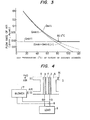
- the apparent moisture content (relative humidity) in the air in the oxidant chamber becomes small as the temperature of the air in the oxidant chamber increaees .
- the relative humidity of the fed air becomes 10% (density about 0.3 g/l) . Accordingly, the effect of moisture content on cell performance is substantially small at a temperature above about 60°C .
- the air flow rate necessary for bettery operation is one that exceeds Q N and is expressed by formulas (13) and (14).
- the battery in a fuel cell battery which uses an acidic electrolyte and is to be operated at a low temperature of 100°C or below, the battery can be operated with a high level of performance by setting the air flow rate to be fed to the air chamber so an to sattisfy the following formula (15) :
- the flow rate of air represented by formula (15) is the minimum value. Accordingly, the air must be fed to the air chamber is in an amount larger than the amount determined by formula (15). Since the amount of air caliculated by formula (15) is an amount of air whose moisture content is zero . Therefore, in practical cases (i.e , the moiature content may change from about 10% to about 90%), the amount of air to be fed should be increased in accordance with the moisture content.
- the quantity of oxygen-containing gas to be fed to the oxidant electrode should preferably be within the range expressed by the following equation:
- the state of wetness or the amount of water on the oxidant electrode is controlled adequately.
- the Q N exceeds 20 x 10 -0.3T0.5 x I(1/min ⁇ cell)
- the oxidant electrods is too dry.
- the quantity Q N is less than 6 X 10 -0.3T0.5 X I(1/min ⁇ cell)
- the oxidant electrode is too wet.
- the most preterable range of Q N is from (8 to 15) X 10 -0.3T0.5 X I(1/mi.n ⁇ cell).
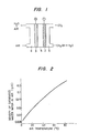
- the fuel cell comprises oxidant electrode 3 consisting of porous, water-repellent graphite carrier and catalytic platinum carried thereon, fuel electrode 2 made of the same material as that of oxidant electrode, and a diluted sulfuric acid layer 4 disposed between the electrodes .
- oxidant electrode 3 consisting of porous, water-repellent graphite carrier and catalytic platinum carried thereon
- fuel electrode 2 made of the same material as that of oxidant electrode
- a diluted sulfuric acid layer 4 disposed between the electrodes .
- the materials and methods of producing the electrodes have been well known in the field of fuel cells.
- catalysts for electrodes there have been known various metals such as platinum group metals and combinations of platinum group metals and other metals such as tin, ruthenium.
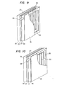
- Figure 4 shows the case in which the fuel cell battery is operated at a predetermined temperature.
- a voltage taken out from part of the wiring connected to a load 9 is applied to the terminal of a blower 7 to provide a terminal voltage for the blower 7 corresponding to a load current.
- the air flow rate eropeseed by formula (15) can be easily obtained by adjasting the terminal voltage of the blower to match the load current by means of an adjuster 8. It is also possible to operate the blower 7 by a voltage circuit (not shown) operated by a voltage signal from the adjuster 8, instead of directly connecting the adjuster to the voltage terminal of the blower 7. According to this system, the air flow rate can be controlled in accordance with changes in the load at a constant temperature using a control circuit (not shown).
- the control circuit may comprise a temperature sensor for the gas temperature at an outlet of the oxidant chamber and a controller for controlling a terminal voltage of blower 7 in response to the signal of the temperature sensor.
- FIG. 5 shows the circuit construction of another embodiment of the present invention which makes it possible to control the air flow rate Q N in accordance with fornule (15) even when the operating temperature T of the battery and the battery current I change.
- the circuit includes a constant voltage circuit, AVR 10 (three terminal- positive voltage regulator, MC-78M12AC, manufactured by Motolora connected to the load 9 and a control circuit, controller 11 which is connected to the constant voltage circuit 10 and to the load 9 and can control the temperature (thermocouple 12) inside the air chamber and the terminal voltage of the blower 7 with respect to changes in the load current.
- AVR 10 three terminal- positive voltage regulator, MC-78M12AC, manufactured by Motolora connected to the load 9 and a control circuit, controller 11 which is connected to the constant voltage circuit 10 and to the load 9 and can control the temperature (thermocouple 12) inside the air chamber and the terminal voltage of the blower 7 with respect to changes in the load current.
- the control circuit 11 comprises a temperature sensor and a computing means which produces a signal as an output for controlling the blower speed. in response to the sensor signal.
- the sensor signal is firat compared with predetermined levels by a comparator so that a necessary level can be determined .
- the output signal for controlling the blower speed is produced.
- the battery operation can be carried out very efficiently even when the load shows a drastic change. Thouth the control circuit must be additionallyl disposed, the increase in the space due to the control circuit is extremely small compared with the space required for the apparatus as a whole .
- the water generated on the air electrode can be efficiently discharged, the oxidation reaction proceeds effectively and the battery can be operated with a high level of performance' for extended periods of time. Moreover, the control of the air flow rate required to discharge the water on the air electrode can be effected simply and easily .
- FIG 6 shows this embodiment of the present invention.
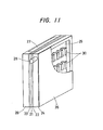
- the fuel electrode 22 and oxidant electrode 23 oppose each other with an electrolyte chamber 21 between them, the fuel chamber 25 is defined by a fuel chamber frame 24 on the fuel electrode 22 side, and the oxidant chamber 27 is defined by an orident chamber frame 26 on the oxidant electrode 23 side.
- the fuel chamber 25 is constructed by the fuel chamber frame 24 consisting of a carbon plate (Hitabate 104, manufactured by Hitachi Cbemical lnd., Co.) formed by sintering carbon powder of a polymeric material and a fuel feed port 28 is disposed on the fuel chamber frame 24.
- the carbon plate is not permeable to gas and liquid.
- the thickness of the carbon plate may vary in the range of 0.5 to 5 mm.
- the port 28 may be disposposed either at an upper part or at the lower part of the frame 24.
- the liquid fuel is fed to the fuel chamber 25 .
- Gas passages 31 are defined inside the fuel chamber 25 by a gas separation layer 30 obtained by shaping a porous material which is chemically inert or stable to the electrolyte and fuel and consists of a laminste of carbon fibers or synthetic fibers such as polypropylene fiber into a groove-like duct, and then impregnating the duct with a solution (POLYFLOW, manufactured by Daikin Kogyo, Ltd., Japan. an average particle size : 0.3 ⁇ m) formed by dispersing fine particles of polytetrafluoroethylene in water or the like for the purpose of water- repeUency.
- a solution POLYFLOW, manufactured by Daikin Kogyo, Ltd., Japan. an average particle size : 0.3 ⁇ m
- the gas separation layer 30 (or 14 in Figures 4 and 5) must be permoable only to gas such as CO 2 , and has a thickness of, for example, several tens microns to several mm.
- the gas separation layer 30 cuts off the liquid and permits only gas to pass therethrough.
- Each gas passesge 31 made of the same material as that of gas separator 30 has a shape such as shown in Figures 8a through 8d, and is a square or cylindrical hollow whose bottom is sealed but whose upper surface is open.
- the gas passage 31 may have a through-hole structure instead of the closed bottom and the duct may extend on both side surfaces instead of the upper surface or may be horisontal.
- the gas passages 31 are fixed to the fuel chamber frame 24 and are sealed lest the fuel inside the fuel obember 25 leak.
- the hollow portion of each gas passage 31 comes into contact with the atmosphere.
- the material that forms the gas passages 31 is not the same as that of the gas separation layer 30 but is the same as that of the fuel chamber frame 24 forming the fuel chamber 25, and its ridge surface is adhered or bonded to the ridge surface in order to prevent the fuel from permeating the hollow portion.
- Edges of the gas separation layer of e .g. in Figure 8a or 8c are in direct contact with the fuel electrode .
- the gas generated on the fuel electrode 22 can be easily diecharged to the outside through the ducts 31, it does not stay in the fuel chamber 25, and consequently the fuel can be easily fed to the fuel electrode 22 and the battery performance is not reduced.
- Figure 9 shows atill another embodiment of the present invention, in which the hollow portion of the hollow gas passage 31 is filled with a solid, porous material made of the same material as that of the gas separation layer 30.
- This construction expands the range of the shapes that may be employed and permits more effective use of the internal space of the fuel chamber.
- the disposition of the gas separation layer 30 is not limited to the vertical direction, and can be any direction that permits gas discharge, including discharge from the side surfaces .
- Figures 10 and 11 show still other embodiments of the present invention, in which the resulting gas is separated by the separation layer 30 and discharged from the side surfaces of the fuel chamber 25 to the atmosphere.
- the gas can be discharged through the adjacent oxidant chamber 27 that is next to the fuel chamber of an adjoining cell.
- the side of the fuel chamber frame 24 opposite the side adjacent to the fuel electrode is covered with a gas permeable film or sheet made of the same material or having the same function as that of the separation layer 30.
- a gas permeable film or sheet made of the same material or having the same function as that of the separation layer 30. obtained by subjecting a fibrous material to water-repolleacy treatment, such as fibrous polytetrafluoroethylene film or sheet marketed by W .L . Gore Co. as GORE-TEX.
- each separation layer 30 is interposed in such a manner as to come into intimate contact with the fuel electrode 22 and with the diaphragm 35 .
- the battery operation can be attained only by the diaphragm 35 without using the separation layer 30.
- the resulting gas formed on the fuel electrode 22 is separated from the fuel by the separation layer 30 and is discharged through the separation layer 30 and the gas pernsable film or sheet 35 made of such as GORE-TEX into the atmoaphere.
- the gas does not accurmulste in the fuel chamber 25 but permits smooth supply of the fuel. Hence, lowering of the battery performance is prevented.
- the fuel chamber to which the liquid fuel is supplied can be sealed with respect to the liquid and the resulting gas can be discharged from the fuel chamber without circulating the fuel liquid or a mixed liquid of the fuel liquid and the electrolyte.
- the fuel cell battery of the invention enables the elimination of the circulating pump .
- the embodiment simplifies the structure, reduces the size and weight of the battery battery and makes it possible to use the battery in all postures.
Landscapes
- Life Sciences & Earth Sciences (AREA)
- Engineering & Computer Science (AREA)
- Manufacturing & Machinery (AREA)
- Sustainable Development (AREA)
- Sustainable Energy (AREA)
- Chemical & Material Sciences (AREA)
- Chemical Kinetics & Catalysis (AREA)
- Electrochemistry (AREA)
- General Chemical & Material Sciences (AREA)
- Fuel Cell (AREA)
Applications Claiming Priority (2)
| Application Number | Priority Date | Filing Date | Title |
|---|---|---|---|
| JP130316/81 | 1981-08-21 | ||
| JP56130316A JPS5834574A (ja) | 1981-08-21 | 1981-08-21 | 燃料電池 |
Publications (3)
| Publication Number | Publication Date |
|---|---|
| EP0073044A2 true EP0073044A2 (fr) | 1983-03-02 |
| EP0073044A3 EP0073044A3 (en) | 1983-09-28 |
| EP0073044B1 EP0073044B1 (fr) | 1986-12-30 |
Family
ID=15031403
Family Applications (1)
| Application Number | Title | Priority Date | Filing Date |
|---|---|---|---|
| EP82107655A Expired EP0073044B1 (fr) | 1981-08-21 | 1982-08-20 | Batterie d'éléments à combustible avec électrolyte acide |
Country Status (3)
| Country | Link |
|---|---|
| EP (1) | EP0073044B1 (fr) |
| JP (1) | JPS5834574A (fr) |
| DE (1) | DE3274930D1 (fr) |
Cited By (6)
| Publication number | Priority date | Publication date | Assignee | Title |
|---|---|---|---|---|
| EP0137327A3 (en) * | 1983-09-14 | 1986-04-09 | Hitachi, Ltd. | Liquid fuel cell |
| EP0716463A3 (fr) * | 1994-11-11 | 1996-11-13 | Toyota Motor Co Ltd | Pile à combustible polyélectrolyte et méthode pour contrÔler son fonctionnement |
| EP0867963A3 (fr) * | 1997-03-25 | 2002-09-04 | Matsushita Electric Industrial Co., Ltd. | Pile à combustible à électrolyte polymère |
| EP1280218A1 (fr) * | 2001-07-27 | 2003-01-29 | Abb Research Ltd. | Méthode pour régler la concentration de methanol dans des piles à combustible directes au méthanol |
| WO2003088391A3 (fr) * | 2002-04-08 | 2004-04-15 | Motorola Inc | Commande de transport de gaz dans une pile a combustible |
| EP1476238A4 (fr) * | 2002-02-19 | 2008-08-27 | Mti Microfuel Cells Inc | Systeme de pile a combustible a oxydation directe simplifiee |
Families Citing this family (4)
| Publication number | Priority date | Publication date | Assignee | Title |
|---|---|---|---|---|
| KR100912157B1 (ko) | 2001-07-18 | 2009-08-14 | 텔-아비브 유니버시티 퓨처 테크놀로지 디벨롭먼트 엘.피. | 프로톤 전도막을 구비하고 물과 연료에 대한 처리를 개선한 연료 전지 |
| JP3775349B2 (ja) | 2002-06-03 | 2006-05-17 | 株式会社デンソー | 回転電機の固定子巻線の製造方法、巻線構造および巻線の製造方法 |
| TW558852B (en) * | 2002-07-12 | 2003-10-21 | Asia Pacific Fuel Cell Tech | Control apparatus and method of fuel cell set |
| KR100776471B1 (ko) | 2006-05-17 | 2007-11-28 | 삼성에스디아이 주식회사 | 세미-패시브형 연료전지 시스템의 특성회복장치 |
Family Cites Families (5)
| Publication number | Priority date | Publication date | Assignee | Title |
|---|---|---|---|---|
| US3992223A (en) * | 1967-01-04 | 1976-11-16 | Siemens Aktiengesellschaft | Method and apparatus for removing reaction water from fuel cells |
| US3935028A (en) * | 1971-06-11 | 1976-01-27 | Siemens Aktiengesellschaft | Fuel cell set and method |
| US4160856A (en) * | 1974-01-25 | 1979-07-10 | Societe Generale De Constructions Electriques Et Mecaniques"Alsthom Et Cie | Novel fuel cell containing novel means for removal of carbonates |
| DE2533215C3 (de) * | 1975-07-25 | 1980-08-14 | Licentia Patent-Verwaltungs-Gmbh, 6000 Frankfurt | Verfahren zur Konstanthaltung der Betriebstemperatur und Elektrolytkonzentration einer für Rohgas/Luft-Betrieb ausgebildeten Brennstoffzellenbatterie mit festgelegtem sauren Elektrolyten |
| US4169917A (en) * | 1978-07-10 | 1979-10-02 | Energy Research Corporation | Electrochemical cell and separator plate thereof |
-
1981
- 1981-08-21 JP JP56130316A patent/JPS5834574A/ja active Pending
-
1982
- 1982-08-20 DE DE8282107655T patent/DE3274930D1/de not_active Expired
- 1982-08-20 EP EP82107655A patent/EP0073044B1/fr not_active Expired
Cited By (11)
| Publication number | Priority date | Publication date | Assignee | Title |
|---|---|---|---|---|
| EP0137327A3 (en) * | 1983-09-14 | 1986-04-09 | Hitachi, Ltd. | Liquid fuel cell |
| EP0716463A3 (fr) * | 1994-11-11 | 1996-11-13 | Toyota Motor Co Ltd | Pile à combustible polyélectrolyte et méthode pour contrÔler son fonctionnement |
| US5939218A (en) * | 1994-11-11 | 1999-08-17 | Toyota Jidosha Kabushiki Kaisha | Polyelectrolytic fuel cell and the method of controlling the operation thereof |
| EP0867963A3 (fr) * | 1997-03-25 | 2002-09-04 | Matsushita Electric Industrial Co., Ltd. | Pile à combustible à électrolyte polymère |
| EP1677379A1 (fr) * | 1997-03-25 | 2006-07-05 | Matsushita Electric Industrial Co., Ltd. | Pile à combustible à électrolyte polymère |
| EP1280218A1 (fr) * | 2001-07-27 | 2003-01-29 | Abb Research Ltd. | Méthode pour régler la concentration de methanol dans des piles à combustible directes au méthanol |
| EP1476238A4 (fr) * | 2002-02-19 | 2008-08-27 | Mti Microfuel Cells Inc | Systeme de pile a combustible a oxydation directe simplifiee |
| US7638215B2 (en) | 2002-02-19 | 2009-12-29 | Mti Microfuel Cells Inc. | Method of controlling delivery of fuel to a direct oxidation fuel cell |
| WO2003088391A3 (fr) * | 2002-04-08 | 2004-04-15 | Motorola Inc | Commande de transport de gaz dans une pile a combustible |
| US6908500B2 (en) | 2002-04-08 | 2005-06-21 | Motorola, Inc. | System and method for controlling gas transport in a fuel cell |
| CN1659730B (zh) * | 2002-04-08 | 2010-12-08 | 摩托罗拉公司(在特拉华州注册的公司) | 控制燃料电池中气体传输 |
Also Published As
| Publication number | Publication date |
|---|---|
| EP0073044A3 (en) | 1983-09-28 |
| EP0073044B1 (fr) | 1986-12-30 |
| JPS5834574A (ja) | 1983-03-01 |
| DE3274930D1 (en) | 1987-02-05 |
Similar Documents
| Publication | Publication Date | Title |
|---|---|---|
| US4612261A (en) | Fuel cell battery using acidic electrolyte | |
| EP0137327B1 (fr) | Pile à combustible liquide | |
| US5441821A (en) | Electrochemical fuel cell system with a regulated vacuum ejector for recirculation of the fluid fuel stream | |
| JP2022167389A (ja) | 燃料電池システム及び飛行体 | |
| KR100803895B1 (ko) | 연료 전지 발전 장치 및 연료 전지 발전 장치의 작동 효율을 증가시키는 방법 | |
| US5328777A (en) | Cathode cover for metal-air cell | |
| US4729932A (en) | Fuel cell with integrated cooling water/static water removal means | |
| US3518123A (en) | Metal/air battery | |
| US6558827B1 (en) | High fuel utilization in a fuel cell | |
| EP0073044A2 (fr) | Batterie d'éléments à combustible avec électrolyte acide | |
| US3411951A (en) | Power supply comprising in combination a fuel cell stack and a humidity exchange scrubber unit | |
| CA1202068A (fr) | Pile a combustible avec systeme d'apport en cascade de l'electrolyte | |
| WO1996019838A1 (fr) | Accumulateur metal-air contenant une quantite minimale d'electrolyte | |
| US4782279A (en) | Method and arrangement for charging a sealed, secondary electrochemical power source | |
| US4212891A (en) | Method and apparatus for storing foodstuffs | |
| EP0105592B1 (fr) | Générateur électrochimique | |
| JPH10284096A (ja) | 固体高分子電解質型燃料電池 | |
| EP1798796B1 (fr) | Procédé d entraînement d équipement de production d énergie à pile à combustible et équipement de production d énergie à pile à combustible | |
| AU618704B1 (en) | Gas-recirculating electrode for electrochemical system | |
| JPH11191423A (ja) | 固体高分子型燃料電池の運転方法 | |
| US20070048571A1 (en) | Fuel cell system | |
| JPS5835875A (ja) | 液体燃料直接発電燃料電池 | |
| US4478916A (en) | Method and apparatus for operating aqueous galvanic high energy cells | |
| US20040058206A1 (en) | Method for improving the water balance of fuel cells | |
| EP0171285A2 (fr) | Procédé de fonctionnement d'une batterie secondaire à électrolyte de bromure de zinc |
Legal Events
| Date | Code | Title | Description |
|---|---|---|---|
| PUAI | Public reference made under article 153(3) epc to a published international application that has entered the european phase |
Free format text: ORIGINAL CODE: 0009012 |
|
| AK | Designated contracting states |
Designated state(s): CH DE FR GB IT LI NL SE |
|
| PUAL | Search report despatched |
Free format text: ORIGINAL CODE: 0009013 |
|
| AK | Designated contracting states |
Designated state(s): CH DE FR GB IT LI NL SE |
|
| 17P | Request for examination filed |
Effective date: 19830930 |
|
| GRAA | (expected) grant |
Free format text: ORIGINAL CODE: 0009210 |
|
| AK | Designated contracting states |
Kind code of ref document: B1 Designated state(s): CH DE FR GB IT LI NL SE |
|
| PG25 | Lapsed in a contracting state [announced via postgrant information from national office to epo] |
Ref country code: LI Effective date: 19861230 Ref country code: IT Free format text: LAPSE BECAUSE OF FAILURE TO SUBMIT A TRANSLATION OF THE DESCRIPTION OR TO PAY THE FEE WITHIN THE PRESCRIBED TIME-LIMIT;WARNING: LAPSES OF ITALIAN PATENTS WITH EFFECTIVE DATE BEFORE 2007 MAY HAVE OCCURRED AT ANY TIME BEFORE 2007. THE CORRECT EFFECTIVE DATE MAY BE DIFFERENT FROM THE ONE RECORDED. Effective date: 19861230 Ref country code: CH Effective date: 19861230 |
|
| REF | Corresponds to: |
Ref document number: 3274930 Country of ref document: DE Date of ref document: 19870205 |
|
| ET | Fr: translation filed | ||
| REG | Reference to a national code |
Ref country code: CH Ref legal event code: PL |
|
| PLBE | No opposition filed within time limit |
Free format text: ORIGINAL CODE: 0009261 |
|
| STAA | Information on the status of an ep patent application or granted ep patent |
Free format text: STATUS: NO OPPOSITION FILED WITHIN TIME LIMIT |
|
| 26N | No opposition filed | ||
| PGFP | Annual fee paid to national office [announced via postgrant information from national office to epo] |
Ref country code: GB Payment date: 19930810 Year of fee payment: 12 |
|
| PGFP | Annual fee paid to national office [announced via postgrant information from national office to epo] |
Ref country code: FR Payment date: 19930818 Year of fee payment: 12 |
|
| PGFP | Annual fee paid to national office [announced via postgrant information from national office to epo] |
Ref country code: DE Payment date: 19931028 Year of fee payment: 12 |
|
| PG25 | Lapsed in a contracting state [announced via postgrant information from national office to epo] |
Ref country code: GB Effective date: 19940820 |
|
| EAL | Se: european patent in force in sweden |
Ref document number: 82107655.1 |
|
| GBPC | Gb: european patent ceased through non-payment of renewal fee |
Effective date: 19940820 |
|
| PG25 | Lapsed in a contracting state [announced via postgrant information from national office to epo] |
Ref country code: FR Effective date: 19950428 |
|
| PG25 | Lapsed in a contracting state [announced via postgrant information from national office to epo] |
Ref country code: DE Effective date: 19950503 |
|
| REG | Reference to a national code |
Ref country code: FR Ref legal event code: ST |
|
| PGFP | Annual fee paid to national office [announced via postgrant information from national office to epo] |
Ref country code: SE Payment date: 19950811 Year of fee payment: 14 |
|
| PGFP | Annual fee paid to national office [announced via postgrant information from national office to epo] |
Ref country code: NL Payment date: 19950830 Year of fee payment: 14 |
|
| PG25 | Lapsed in a contracting state [announced via postgrant information from national office to epo] |
Ref country code: SE Effective date: 19960821 |
|
| PG25 | Lapsed in a contracting state [announced via postgrant information from national office to epo] |
Ref country code: NL Effective date: 19970301 |
|
| NLV4 | Nl: lapsed or anulled due to non-payment of the annual fee |
Effective date: 19970301 |
|
| EUG | Se: european patent has lapsed |
Ref document number: 82107655.1 |