EP0073153A2 - Verbesserte mit festem Elektrolyt arbeitende Vorrichtung zum Auffinden von Gas - Google Patents
Verbesserte mit festem Elektrolyt arbeitende Vorrichtung zum Auffinden von Gas Download PDFInfo
- Publication number
- EP0073153A2 EP0073153A2 EP82304417A EP82304417A EP0073153A2 EP 0073153 A2 EP0073153 A2 EP 0073153A2 EP 82304417 A EP82304417 A EP 82304417A EP 82304417 A EP82304417 A EP 82304417A EP 0073153 A2 EP0073153 A2 EP 0073153A2
- Authority
- EP
- European Patent Office
- Prior art keywords
- gas
- monitored
- cell
- environment
- solid electrolyte
- Prior art date
- Legal status (The legal status is an assumption and is not a legal conclusion. Google has not performed a legal analysis and makes no representation as to the accuracy of the status listed.)
- Ceased
Links
Images
Classifications
-
- G—PHYSICS
- G01—MEASURING; TESTING
- G01N—INVESTIGATING OR ANALYSING MATERIALS BY DETERMINING THEIR CHEMICAL OR PHYSICAL PROPERTIES
- G01N27/00—Investigating or analysing materials by the use of electric, electrochemical, or magnetic means
- G01N27/26—Investigating or analysing materials by the use of electric, electrochemical, or magnetic means by investigating electrochemical variables; by using electrolysis or electrophoresis
- G01N27/403—Cells and electrode assemblies
- G01N27/406—Cells and probes with solid electrolytes
- G01N27/407—Cells and probes with solid electrolytes for investigating or analysing gases
- G01N27/4078—Means for sealing the sensor element in a housing
Definitions
- This invention generally relates to electrochemical type gas-measuring apparatus, and more particularly to methods of minimizing effects of gas leakage caused by mechanical damage, e.g., seal damage or solid electrolyte breakage in such apparatus.
- Solid electrolyte compositions have been used in gas sensing apparatus to measure oxygen, combustibles, pollutants, i.e. 50 2 , C0 2 , etc. and have provided a basis for applications ranging from medical instrumentation to industrial process and stack gas analyzers.
- a solid electrolyte electrochemical cell develops an electrical signal, current or voltage, on the basis of ion conductivity which is a function of the content of a particular gas species of interest within a monitored gas environment.
- the application of a solid electrolyte electrochemical cell exhibiting oxygen ion conductivity to monitor the oxygen content of a gas environment is described in detail in United States Reissue Patent 28,792 which is assigned to the assignee of the present invention.
- the solid electrolyte electrochemical cell which consists of an oxygen ion conductive solid electrolyte having a sensing electrode disposed on one surface and a reference electrode disposed on an opposite surface, develops an EMF signal of magnitude in accordance with the Nernst equation in response to a difference in the oxygen partial pressure between the sensing and reference electrodes.
- a stable or known oxygen reference environment is maintained in contact with the reference electrode.
- This reference environment is isolated, through appropriate sealing means, from the measured gas environment contacting the sensing electrode.
- the same basic mode of operation of a solid electrolyte electrochemical cell as employed for the measurement of combustibles is described in U.S. Patent 4,158,166, which is assigned to the assignee of the present invention.
- the electrochemical cell is operated in a pumping mode to introduce oxygen from the reference source to combustibly react with combustible constituents at the sensing electrode with the cell current developed as a result of the ion conductivity providing an indication of the combustibles content of a measured gas environment.
- the sealing, or isolation, of the measured gas environment from the reference gas environment poses significant practical problems in developing a trouble- free gas-sensing apparatus due to the fragile nature of the ceramic material comprising the solid electrolyte element. This problem is further compounded when developing a high temperature solid electrolyte gas-sensing apparatus, particularly when it is intended for monitoring the gas constituents of an industrial corrosive environment.
- the electrolyte material is limited to a relatively small disc-shaped solid electrolyte element having electrodes disposed on opposite surfaces thereof with the electrochemical cell then being sealed within a relatively strong mechanical tubular housing by an appropriate bonding technique, e.g. brazing.
- an appropriate bonding technique e.g. brazing.
- a second approach is to utilize a closed end solid electrolyte tube with the electrodes being disposed on opposite surfaces of the closed end. The tube extends into a relatively cool and favorable environment before a transition is made through a flange or an adapter. This approach essentially eliminates the seal problem but exposes the fragile ceramic material to mechanical damage.
- the flowing reference gas is exhausted from the electrochemical cell gas sensor at a location remote from the solid electrolyte electrochemical cell. It has been determined experimentally that if the flowing reference gas is vented from the solid electrolyte electrochemical cell assembly to the measured gas environment at a location which is close to the electrochemical cell, the gas pressure across the solid electrolyte electrochemical cell will be essentially equalized. The equalization of the gas pressure across the electrochemical cell minimizes the likelihood of leakage between the gas environments contacting the sensing and reference electrodes of the electrochemical cell and eliminates potential back pressures which could result in mechanical fracturing of the solid electrolyte element.
- This equalization of total gas pressures on either side of the solid electrolyte element further eliminates the requirement for adjusting the pressure of the reference gas environment to approximate that of the measured gas environment in order to assure the validity of the gas measuring electrical signal developed by the solid electrolyte electrochemical cell.
- This disclosed technique essentially eliminates the need for employing a long fragile closed solid electrolyte tube in one gas apparatus design approach, and the difficult high temperature sealing requirements of the combination of a solid electrolyte cell and a mechanical supporting tube.
- the present invnetion resides in a gas measuring cell of the electrochemical type, wherein a monitored gas and a flowing reference gas are admitted on opposte sides of a solid electrolyte cell element and wherein said monitored gas is discharged from the cell in a predetermined direction, a method for equalizing the pressures of said flowing reference gas and a monitored gas on either side of the gas measuring solid electrolyte cell element, said method comprising the steps of: venting the flowing reference gas from a reference gas environment to a monitored gas environment at a location sufficiently close to the solid electrolyte cell, said location being downstream from the cell element in said predetermined direction to make the gas pressure of the reference gas and monitored gas on either side of said solid electrolyte cell substantially equal, said location being selected to prevent the vented reference gas from affecting the measurement of the monitored gas environment by said electrochemical cell.
- novel reference gas vent technique has particular application to gas sensors employing solid electrolyte electrochemical cells, the concept is also applicable to electrochemical cell gas analyzers using a gel or liquid electrolyte.
- the reference gas is supplied to the reference electrode of the solid electrolyte electrochemical cell and subsequently vented to an atmosphere remote from the process gas environment being measured by the solid electrolyte gas analyzer. It has been determined experimentally, that if the reference gas is vented or discharged to the processed or monitored gas environment at a location relatively close to the solid electrolyte electrochemical cell, the pressure of the reference gas contacting the reference electrode of the solid electrolyte electrochemical cell can be maintained substantially equal to the pressure of the processed gas contacting the sensing electrode. This is accomplished regardless of variations in the process gas pressure.
- This technique not only eliminates the error in the electrochemical cell signal caused by process gas pressure variations, but also reduces the pressure drop across the ceramic solid electrolyte sensor sufficiently to minimize the gas leakage between the process gas and the reference gas environments.
- the reference gas vent is located so as not to alter the process gas in the vicinity of the sensing electrode of the electrochemical cell.
- the gas analyzer provides for introducing test or calibration gases to the sensing electrode of the electrochemical cell it is necessary to locate the reference gas vent so as to avoid mixing the vented reference gas with the calibration or test gas.
- Typical embodiments of solid electrolyte gas analyzers incorporating the novel reference vent technique are described below with reference to the illustrations of Figs. 1 and 2.
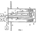
- a disc-shaped solid electrolyte electrochemical concentration' cell 20 is sealed within a support tube 30 via a seal 31.
- the support tube 30, which may be typically a metal member, passes through a first bulk head member 40 and a second bulk head 50.
- the second bulk head 50 includes a tubular member 52 which supports an annular porous dust seal 54 which contacts an outer tubular shield member 42 extending from the bulk head 40.
- the porous seal 54 reduces the passage of particulate material from the process gas environment PG into the gas analyzer assembly 10.
- the tubular protective shield 42 is secured within an opening of the wall W of the process gas enclosure which may typically be a stack in an industrial environment.
- the solid electrolyte electrochemical cell 20 consists of an ion conductive solid electrolyte element 22 having a reference electrode 24 and a sensing electrode 26 disposed on opposite surfaces thereof.
- the composition of the solid electrolyte member 22 is selected so as to render the cell 20 responsive to a particular gas constituent of interest in the process, or monitored gas, gas environment PG.
- the gas constituent of interest may be oxygen, a combustibles constituent, a pollutant constituent, etc.
- a known or stable reference gas environment RG is maintained in contact with the reference electrode 24 by flowing a reference gas at a controlled rate from a remote reference gas source RS through an inlet tube member 60.
- the electrical signal developed by the electrochemical cell 20 in response to the partial pressure of the gas constituent of interest of the process gas environment PG is monitored by a remote measuring circuit MC connected to the electrodes 24 and 26 via electrical leads 62 and 64.
- a test gas inlet tube 65 is provided for supplying a calibration gas within the tubular member 52 from test gas source TS for contacting the sensing electrode 26.
- the gas sensing assembly described thus far is indicative of commercially available gas analyzer probe assemblies.
- the commercially available analyzers vent the reference gas to the atmosphere A, remote from the process gas environment PG.
- a reference gas vent 70 illustrated as an aperture in the support tube 30, provides for the venting of the reference gas from the reference gas environment RG through the annular chamber 74 defined as the space between the tubular members 30 and 42, through the porous seal 54 and into the process gas environment PG as indicated by the arrows.
- the location of the vent 70 assures the passage of the reference gas into the process gas environment PG without diluting or interfering with the gas composition of the process gas environment or the test gas at the sensing electrode 26 of the electrochemical cell 20.
- the venting of the reference gas from a vent location 70 in close proximity to the electrochemical cell 20 into the processed gas environment PG in the direction of the downstream flow of the processed gas PG achieves the benefits of substantial-equalization of gas pressure across the solid electrolyte electrochemical cell 20 for a predetermined reference gas flow rate.
- the reference gas flow rate is set such that the difference in gas pressure between the reference gas environment RG and process gas environment PG across the cell 20 corresponds to the pressure drop established by the reference gas vent path, i.e., vent 70.
- the gas pressure of the reference gas environment RG is thus maintained substantially equal to the gas pressure of the processed gas or monitored gas environment.
- the pressure drop across vent 70 created by the reference gas flow rate results in the reference gas functioning as a purge gas to prevent corrosive gases of the process gas environment PG from entering this area of the assembly 10.
- Fig. 1 illustrates a gas analyzer probe assembly for the in-situ measurement of the gas constituent of a process gas environment
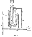
- the gas analyzer 100 of Fig. 2 is mounted outside the process gas environment PG. It responds to a sample of the process gas drawn through a sample tube ST to provide a measurement of the partial pressure of a gas constituent of interest of the process gas GP.
- a combination of a disc-shaped solid electrolyte electrochemical cell 20 sealed within a tubular support member 30, comparable to that described above with reference to Fig. 1, is sealed within a tubular housing 110 through the use of a seal member 112.
- a pump P draws a sample of the process gas into the sample gas flow tube ST.
- An inlet tube 120 which provides gas flow communication between the sample gas flow tube ST and the internal volume of the housing 110 exposes a sensing electrode 26 of the electrochemical cell 20 to a sample of the process gas environment PG.
- the sample gas is then drawn from the internal volume of the housing 110 through the output tube 114 back into the sample flow tube ST.
- a flowing reference gas is brought into contact with the reference electrode 24 of the electrochemical cell 20 via a reference gas inlet tube 120 which enters the support tube 30 through a gas seal 32.
- the reference gas flow is supported by the action of the pump P which draws the reference gas from the support tube 30 through a reference gas exhaust tube 150 and introduces the exhaust reference gas into the sample gas flow tube ST at a location slightly downstream from the sample gas inlet tube 112.
- the coupling of the exhaust reference gas from the reference gas environment of the cell 20 to the sample gas flow tube ST at a location slightly downstream from the sample gas inlet tube 112 avoids mixing of the reference gas with the sample gas being measured by the cell 20. It is however sufficiently close to the inlet tube 112 so as to achieve the desired gas pressure equalization across the electrochemical cell 20 to realize the objectives defined above.
- the conventional need for a leak-tight seal between the sensing electrode surface of the electrochemical cell 20 and the reference electrode surface of the electrochemical cell 20 is minimized through the use of the reference gas vent technique illustrated in Figs. 1 and 2 due to the fact that the total gas pressure difference across the electrochemical cell 20 is held to a value equal to the pressure drop through the reference gas vent path as determined by controlling the reference gas flow rate.
Landscapes
- Chemical & Material Sciences (AREA)
- Life Sciences & Earth Sciences (AREA)
- Health & Medical Sciences (AREA)
- Physics & Mathematics (AREA)
- Chemical Kinetics & Catalysis (AREA)
- Electrochemistry (AREA)
- Molecular Biology (AREA)
- Analytical Chemistry (AREA)
- Biochemistry (AREA)
- General Health & Medical Sciences (AREA)
- General Physics & Mathematics (AREA)
- Immunology (AREA)
- Pathology (AREA)
- Measuring Oxygen Concentration In Cells (AREA)
- Secondary Cells (AREA)
Applications Claiming Priority (2)
| Application Number | Priority Date | Filing Date | Title |
|---|---|---|---|
| US29495181A | 1981-08-21 | 1981-08-21 | |
| US294951 | 1981-08-21 |
Publications (2)
| Publication Number | Publication Date |
|---|---|
| EP0073153A2 true EP0073153A2 (de) | 1983-03-02 |
| EP0073153A3 EP0073153A3 (de) | 1983-10-05 |
Family
ID=23135620
Family Applications (1)
| Application Number | Title | Priority Date | Filing Date |
|---|---|---|---|
| EP82304417A Ceased EP0073153A3 (de) | 1981-08-21 | 1982-08-20 | Verbesserte mit festem Elektrolyt arbeitende Vorrichtung zum Auffinden von Gas |
Country Status (3)
| Country | Link |
|---|---|
| US (1) | US4462872A (de) |
| EP (1) | EP0073153A3 (de) |
| AU (1) | AU561654B2 (de) |
Cited By (2)
| Publication number | Priority date | Publication date | Assignee | Title |
|---|---|---|---|---|
| DE3323241A1 (de) * | 1983-06-28 | 1985-01-03 | Koertvelyessy Laszlo | Sauerstoffsonde mit keramikgeschuetzter gaselektrode |
| EP3036535A4 (de) * | 2013-08-13 | 2016-08-03 | Services Petroliers Schlumberger | Co2-konzentrationsmessung in trockengasgemischen |
Families Citing this family (12)
| Publication number | Priority date | Publication date | Assignee | Title |
|---|---|---|---|---|
| JPS62266039A (ja) * | 1986-05-14 | 1987-11-18 | 株式会社東芝 | 超音波診断装置 |
| EP0273304B1 (de) * | 1986-12-19 | 1992-07-15 | Matsushita Electric Industrial Co., Ltd. | Sauerstoffsensor |
| IL82160A (en) * | 1987-04-10 | 1991-03-10 | Technion Res & Dev Foundation | Electrochemical analyzer for measuring the concentration of atoms or molecules in a fluid and method of making same |
| US5007988A (en) * | 1987-09-08 | 1991-04-16 | Westinghouse Electric Corp. | Method for determining the concentration of a plurality of combustible gases in a stream |
| FI81678C (fi) * | 1987-09-08 | 1990-11-12 | Valtion Teknillinen | Spetsstruktur foer en referenselektrod. |
| US5324415A (en) * | 1989-06-09 | 1994-06-28 | Blumenthal Robert N | Apparatus and systems for analyzing a sample of treatment atmosphere having a carbon potential |
| US5296112A (en) * | 1992-06-02 | 1994-03-22 | H.P.S. Merrimac, Inc. | Oxygen monitoring devices |
| US5980728A (en) * | 1996-09-24 | 1999-11-09 | Rosemont Analytical Inc. | Diagnostic method and apparatus for solid electrolyte gas analyzer |
| US5993623A (en) * | 1996-09-24 | 1999-11-30 | Rosemount Analytical Inc. | Solid electrolyte gas analyzer with improved circuit and housing configuration |
| US6120664A (en) * | 1998-01-16 | 2000-09-19 | Patel; Nitin J. | Oxygen analyzer |
| US20060096868A1 (en) * | 2004-11-10 | 2006-05-11 | Siona Bunce | Nickel electroplating bath designed to replace monovalent copper strike solutions |
| WO2020028956A1 (en) * | 2018-08-10 | 2020-02-13 | Ceramic Oxide Fabricators Pty Ltd | Furnace oxygen probe |
Family Cites Families (8)
| Publication number | Priority date | Publication date | Assignee | Title |
|---|---|---|---|---|
| US28792A (en) * | 1860-06-19 | Adjustable carriage-seat | ||
| USRE28792E (en) | 1966-03-15 | 1976-04-27 | Westinghouse Electric Corporation | Electrochemical method for separating O2 from a gas; generating electricity; measuring O2 partial pressure; and fuel cell |
| US3598711A (en) * | 1967-11-15 | 1971-08-10 | Bailey Meter Co | Electrochemical oxygen analyzer |
| US3915828A (en) * | 1973-12-06 | 1975-10-28 | Westinghouse Electric Corp | Solid electrolyte cell assembly |
| US4098650A (en) * | 1976-11-08 | 1978-07-04 | Thermo-Lab Instruments, Inc. | Method and analyzer for determining moisture in a mixture of gases containing oxygen |
| US4284487A (en) * | 1978-10-13 | 1981-08-18 | Milton Roy Company | Oxygen analyzer probe |
| US4264423A (en) * | 1979-09-17 | 1981-04-28 | The United States Of America As Represented By The Secretary Of The Army | Fluidic thermistor/fugacity device |
| DE2945698C2 (de) * | 1979-11-13 | 1989-09-21 | Brown, Boveri & Cie Ag, 6800 Mannheim | Elektrochemische Meßvorrichtung für die Bestimmung des Sauerstoffgehalts in Gasen |
-
1982
- 1982-07-26 AU AU86418/82A patent/AU561654B2/en not_active Ceased
- 1982-08-20 EP EP82304417A patent/EP0073153A3/de not_active Ceased
- 1982-11-16 US US06/442,073 patent/US4462872A/en not_active Expired - Fee Related
Cited By (5)
| Publication number | Priority date | Publication date | Assignee | Title |
|---|---|---|---|---|
| DE3323241A1 (de) * | 1983-06-28 | 1985-01-03 | Koertvelyessy Laszlo | Sauerstoffsonde mit keramikgeschuetzter gaselektrode |
| DE3323241C3 (de) * | 1983-06-28 | 1998-11-12 | Thermo Control Koertvelyessy G | Sauerstoffsonde mit keramikgeschützter Elektrode |
| EP3036535A4 (de) * | 2013-08-13 | 2016-08-03 | Services Petroliers Schlumberger | Co2-konzentrationsmessung in trockengasgemischen |
| US9804117B2 (en) | 2013-08-13 | 2017-10-31 | Schlumberger Technology Corporation | CO2 concentration measurement in dry gas mixtures |
| US10942144B2 (en) | 2013-08-13 | 2021-03-09 | Cameron International Corporation | CO2 concentration measurement in dry gas mixtures |
Also Published As
| Publication number | Publication date |
|---|---|
| AU561654B2 (en) | 1987-05-14 |
| EP0073153A3 (de) | 1983-10-05 |
| AU8641882A (en) | 1983-02-24 |
| US4462872A (en) | 1984-07-31 |
Similar Documents
| Publication | Publication Date | Title |
|---|---|---|
| US3718568A (en) | Electrochemical sensor instrumentation | |
| EP0073153A2 (de) | Verbesserte mit festem Elektrolyt arbeitende Vorrichtung zum Auffinden von Gas | |
| US6370940B2 (en) | Apparatus for determining concentration of a gas | |
| US4377460A (en) | Solid electrolyte gas sensing apparatus | |
| US3966579A (en) | Apparatus for measuring alcohol concentrations | |
| US3915828A (en) | Solid electrolyte cell assembly | |
| JPH0656376B2 (ja) | 電気化学的ガス・センサ | |
| JPS635703B2 (de) | ||
| US4073698A (en) | Method and device for the detection and measurement of carbon monoxide in the presence of hydrogen | |
| EP0060944A1 (de) | Sensor für mit Sauerstoff brennbare Gasmischungen | |
| US4201634A (en) | Method for the detection of hydrazine | |
| US4427525A (en) | Dual gas measuring solid electrolyte electrochemical cell apparatus | |
| US4247380A (en) | Technique for in situ calibration of a gas detector | |
| US5085760A (en) | Electrochemical gas sensors | |
| Kocache | The measurement of oxygen on gas mixtures | |
| EP0993607B1 (de) | Vorrichtung und verfahren zur messung der zusammensetzung eines gases unter verwendung eines ionenleitenden elektrolyten | |
| CN101297195A (zh) | 氮氧化物气体传感器和方法 | |
| JP4175767B2 (ja) | ガス分析計およびその校正方法 | |
| JP2007108018A (ja) | ガス分析装置の校正方法 | |
| EP0248891A1 (de) | Leckprüfer | |
| US4285790A (en) | Sensor for oxygen-combustibles gas mixtures | |
| GB1427395A (en) | Gas measuring probe for industrial applications | |
| JPS62119433A (ja) | フイルムの水素透過係数測定装置 | |
| CA1202678A (en) | Solid electrolyte gas sensing apparatus | |
| US20060254908A1 (en) | Electrochemical solid electrolyte sensor for the detection of oxygen, hydrocarbons and moisture in vacuum environments |
Legal Events
| Date | Code | Title | Description |
|---|---|---|---|
| PUAI | Public reference made under article 153(3) epc to a published international application that has entered the european phase |
Free format text: ORIGINAL CODE: 0009012 |
|
| AK | Designated contracting states |
Designated state(s): BE DE FR GB IT LU NL |
|
| PUAL | Search report despatched |
Free format text: ORIGINAL CODE: 0009013 |
|
| AK | Designated contracting states |
Designated state(s): BE DE FR GB IT LU NL |
|
| 17P | Request for examination filed |
Effective date: 19840405 |
|
| STAA | Information on the status of an ep patent application or granted ep patent |
Free format text: STATUS: THE APPLICATION HAS BEEN REFUSED |
|
| 18R | Application refused |
Effective date: 19890221 |
|
| APAF | Appeal reference modified |
Free format text: ORIGINAL CODE: EPIDOSCREFNE |
|
| RIN1 | Information on inventor provided before grant (corrected) |
Inventor name: NELSON, ROBERT LEONARD |