EP0073156A1 - Appareil pour la mesure et la réception automatiques de l'écoulement urinaire d'un patient - Google Patents
Appareil pour la mesure et la réception automatiques de l'écoulement urinaire d'un patient Download PDFInfo
- Publication number
- EP0073156A1 EP0073156A1 EP82304426A EP82304426A EP0073156A1 EP 0073156 A1 EP0073156 A1 EP 0073156A1 EP 82304426 A EP82304426 A EP 82304426A EP 82304426 A EP82304426 A EP 82304426A EP 0073156 A1 EP0073156 A1 EP 0073156A1
- Authority
- EP
- European Patent Office
- Prior art keywords
- measurement column
- pump
- collection
- optical sensor
- measurement
- Prior art date
- Legal status (The legal status is an assumption and is not a legal conclusion. Google has not performed a legal analysis and makes no representation as to the accuracy of the status listed.)
- Granted
Links
- 238000005259 measurement Methods 0.000 title claims abstract description 92
- 230000002485 urinary effect Effects 0.000 title claims abstract description 68
- 230000003287 optical effect Effects 0.000 claims abstract description 45
- 230000000737 periodic effect Effects 0.000 claims abstract description 6
- 239000007788 liquid Substances 0.000 claims abstract description 5
- 239000012530 fluid Substances 0.000 claims description 19
- 239000000853 adhesive Substances 0.000 claims description 4
- 230000001070 adhesive effect Effects 0.000 claims description 4
- 230000000151 anti-reflux effect Effects 0.000 claims description 4
- 230000002093 peripheral effect Effects 0.000 claims description 2
- 210000002700 urine Anatomy 0.000 abstract description 11
- 210000003734 kidney Anatomy 0.000 description 9
- 230000002572 peristaltic effect Effects 0.000 description 7
- 238000012544 monitoring process Methods 0.000 description 4
- DGAQECJNVWCQMB-PUAWFVPOSA-M Ilexoside XXIX Chemical compound C[C@@H]1CC[C@@]2(CC[C@@]3(C(=CC[C@H]4[C@]3(CC[C@@H]5[C@@]4(CC[C@@H](C5(C)C)OS(=O)(=O)[O-])C)C)[C@@H]2[C@]1(C)O)C)C(=O)O[C@H]6[C@@H]([C@H]([C@@H]([C@H](O6)CO)O)O)O.[Na+] DGAQECJNVWCQMB-PUAWFVPOSA-M 0.000 description 3
- 208000001647 Renal Insufficiency Diseases 0.000 description 3
- 201000006370 kidney failure Diseases 0.000 description 3
- 229910052708 sodium Inorganic materials 0.000 description 3
- 239000011734 sodium Substances 0.000 description 3
- 208000001380 Diabetic Ketoacidosis Diseases 0.000 description 2
- 206010030302 Oliguria Diseases 0.000 description 2
- 230000036772 blood pressure Effects 0.000 description 2
- 238000004140 cleaning Methods 0.000 description 2
- 230000008878 coupling Effects 0.000 description 2
- 238000010168 coupling process Methods 0.000 description 2
- 238000005859 coupling reaction Methods 0.000 description 2
- 238000013461 design Methods 0.000 description 2
- 230000006870 function Effects 0.000 description 2
- NOESYZHRGYRDHS-UHFFFAOYSA-N insulin Chemical compound N1C(=O)C(NC(=O)C(CCC(N)=O)NC(=O)C(CCC(O)=O)NC(=O)C(C(C)C)NC(=O)C(NC(=O)CN)C(C)CC)CSSCC(C(NC(CO)C(=O)NC(CC(C)C)C(=O)NC(CC=2C=CC(O)=CC=2)C(=O)NC(CCC(N)=O)C(=O)NC(CC(C)C)C(=O)NC(CCC(O)=O)C(=O)NC(CC(N)=O)C(=O)NC(CC=2C=CC(O)=CC=2)C(=O)NC(CSSCC(NC(=O)C(C(C)C)NC(=O)C(CC(C)C)NC(=O)C(CC=2C=CC(O)=CC=2)NC(=O)C(CC(C)C)NC(=O)C(C)NC(=O)C(CCC(O)=O)NC(=O)C(C(C)C)NC(=O)C(CC(C)C)NC(=O)C(CC=2NC=NC=2)NC(=O)C(CO)NC(=O)CNC2=O)C(=O)NCC(=O)NC(CCC(O)=O)C(=O)NC(CCCNC(N)=N)C(=O)NCC(=O)NC(CC=3C=CC=CC=3)C(=O)NC(CC=3C=CC=CC=3)C(=O)NC(CC=3C=CC(O)=CC=3)C(=O)NC(C(C)O)C(=O)N3C(CCC3)C(=O)NC(CCCCN)C(=O)NC(C)C(O)=O)C(=O)NC(CC(N)=O)C(O)=O)=O)NC(=O)C(C(C)CC)NC(=O)C(CO)NC(=O)C(C(C)O)NC(=O)C1CSSCC2NC(=O)C(CC(C)C)NC(=O)C(NC(=O)C(CCC(N)=O)NC(=O)C(CC(N)=O)NC(=O)C(NC(=O)C(N)CC=1C=CC=CC=1)C(C)C)CC1=CN=CN1 NOESYZHRGYRDHS-UHFFFAOYSA-N 0.000 description 2
- 230000007246 mechanism Effects 0.000 description 2
- 239000000203 mixture Substances 0.000 description 2
- 230000003204 osmotic effect Effects 0.000 description 2
- 230000001575 pathological effect Effects 0.000 description 2
- 238000011084 recovery Methods 0.000 description 2
- 230000035939 shock Effects 0.000 description 2
- 239000002699 waste material Substances 0.000 description 2
- 208000003918 Acute Kidney Tubular Necrosis Diseases 0.000 description 1
- 206010002660 Anoxia Diseases 0.000 description 1
- 241000976983 Anoxia Species 0.000 description 1
- 208000035143 Bacterial infection Diseases 0.000 description 1
- 208000028399 Critical Illness Diseases 0.000 description 1
- WQZGKKKJIJFFOK-GASJEMHNSA-N Glucose Natural products OC[C@H]1OC(O)[C@H](O)[C@@H](O)[C@@H]1O WQZGKKKJIJFFOK-GASJEMHNSA-N 0.000 description 1
- 206010021143 Hypoxia Diseases 0.000 description 1
- 102000004877 Insulin Human genes 0.000 description 1
- 108090001061 Insulin Proteins 0.000 description 1
- 208000004880 Polyuria Diseases 0.000 description 1
- 206010038540 Renal tubular necrosis Diseases 0.000 description 1
- PNNCWTXUWKENPE-UHFFFAOYSA-N [N].NC(N)=O Chemical compound [N].NC(N)=O PNNCWTXUWKENPE-UHFFFAOYSA-N 0.000 description 1
- 230000007953 anoxia Effects 0.000 description 1
- 208000022362 bacterial infectious disease Diseases 0.000 description 1
- WQZGKKKJIJFFOK-VFUOTHLCSA-N beta-D-glucose Chemical compound OC[C@H]1O[C@@H](O)[C@H](O)[C@@H](O)[C@@H]1O WQZGKKKJIJFFOK-VFUOTHLCSA-N 0.000 description 1
- 238000012742 biochemical analysis Methods 0.000 description 1
- 230000005540 biological transmission Effects 0.000 description 1
- 239000008280 blood Substances 0.000 description 1
- 210000004369 blood Anatomy 0.000 description 1
- 239000003990 capacitor Substances 0.000 description 1
- 210000000748 cardiovascular system Anatomy 0.000 description 1
- 239000012141 concentrate Substances 0.000 description 1
- 239000004020 conductor Substances 0.000 description 1
- 238000011109 contamination Methods 0.000 description 1
- 230000007547 defect Effects 0.000 description 1
- 238000001514 detection method Methods 0.000 description 1
- 230000035619 diuresis Effects 0.000 description 1
- 239000008103 glucose Substances 0.000 description 1
- 230000036541 health Effects 0.000 description 1
- 208000014674 injury Diseases 0.000 description 1
- 229940125396 insulin Drugs 0.000 description 1
- 150000002576 ketones Chemical class 0.000 description 1
- 238000009592 kidney function test Methods 0.000 description 1
- 230000014759 maintenance of location Effects 0.000 description 1
- 238000012986 modification Methods 0.000 description 1
- 230000004048 modification Effects 0.000 description 1
- 230000010412 perfusion Effects 0.000 description 1
- 229920002635 polyurethane Polymers 0.000 description 1
- 239000004814 polyurethane Substances 0.000 description 1
- 230000001737 promoting effect Effects 0.000 description 1
- 230000001954 sterilising effect Effects 0.000 description 1
- 238000004659 sterilization and disinfection Methods 0.000 description 1
- 239000000126 substance Substances 0.000 description 1
- 239000000758 substrate Substances 0.000 description 1
- 239000000725 suspension Substances 0.000 description 1
- 230000008733 trauma Effects 0.000 description 1
- 238000002562 urinalysis Methods 0.000 description 1
Images

Classifications
-
- A—HUMAN NECESSITIES
- A61—MEDICAL OR VETERINARY SCIENCE; HYGIENE
- A61B—DIAGNOSIS; SURGERY; IDENTIFICATION
- A61B5/00—Measuring for diagnostic purposes; Identification of persons
- A61B5/20—Measuring for diagnostic purposes; Identification of persons for measuring urological functions restricted to the evaluation of the urinary system
- A61B5/201—Assessing renal or kidney functions
-
- A—HUMAN NECESSITIES
- A61—MEDICAL OR VETERINARY SCIENCE; HYGIENE
- A61B—DIAGNOSIS; SURGERY; IDENTIFICATION
- A61B5/00—Measuring for diagnostic purposes; Identification of persons
- A61B5/145—Measuring characteristics of blood in vivo, e.g. gas concentration or pH-value ; Measuring characteristics of body fluids or tissues, e.g. interstitial fluid or cerebral tissue
- A61B5/14507—Measuring characteristics of blood in vivo, e.g. gas concentration or pH-value ; Measuring characteristics of body fluids or tissues, e.g. interstitial fluid or cerebral tissue specially adapted for measuring characteristics of body fluids other than blood
-
- A—HUMAN NECESSITIES
- A61—MEDICAL OR VETERINARY SCIENCE; HYGIENE
- A61B—DIAGNOSIS; SURGERY; IDENTIFICATION
- A61B5/00—Measuring for diagnostic purposes; Identification of persons
- A61B5/20—Measuring for diagnostic purposes; Identification of persons for measuring urological functions restricted to the evaluation of the urinary system
- A61B5/207—Sensing devices adapted to collect urine
- A61B5/208—Sensing devices adapted to collect urine adapted to determine urine quantity, e.g. flow, volume
-
- G—PHYSICS
- G01—MEASURING; TESTING
- G01F—MEASURING VOLUME, VOLUME FLOW, MASS FLOW OR LIQUID LEVEL; METERING BY VOLUME
- G01F3/00—Measuring the volume flow of fluids or fluent solid material wherein the fluid passes through the meter in successive and more or less isolated quantities, the meter being driven by the flow
- G01F3/36—Measuring the volume flow of fluids or fluent solid material wherein the fluid passes through the meter in successive and more or less isolated quantities, the meter being driven by the flow with stationary measuring chambers having constant volume during measurement
- G01F3/38—Measuring the volume flow of fluids or fluent solid material wherein the fluid passes through the meter in successive and more or less isolated quantities, the meter being driven by the flow with stationary measuring chambers having constant volume during measurement having only one measuring chamber
Definitions
- the present inventive system relates to fluid output measurement, and more specifically to an automatic urinary output measurement and recording mechanism.
- kidney failure is merely functional and not pathological. Monitoring the urinary output alerts the physician when functional failure is no longer a threat. If urinary output falls beneath 30 cc's per minute, the situation is called oliguria. Oliguria may not respond to a simple increase in fluid intake by parenteral or oral route. Under these circumstances, the urinalysis may aid in determining whether the problem is simply one of under perfusion of the kidneys or of pathological damage. This can often be determined by sodium content of the urine. In patients with acute tubular necrosis, the urinary sodium levels are high while patients whose kidneys are simply under perfused have a low urinary sodium value.
- osmolarity of the urine is the best kidney function test that is available. It may be necessary to repeatedly follow the osmolarity of the urine to determine whether the kidneys are recovering and how seriously they are injured.
- osmolarity greater than 300 mil osmols per litre.
- urinary osmolarity rises and often diuresis ceases.
- diabetic acidosis it may be necessary to measure the hourly composition of the urine with respect to glucose and ketone bodies to make the necessary adjustments in insulin dosage and to determine the extent of recovery from the diabetic acidosis.
- Urinary collection is usually done by inserting a catheter into the bladder and collecting the urinary output into a bag which is measured every hour and charted on the patient's records. This is, of course, not only time consuming and costly but it wastes personnel time. What is more important is that the time required to make accurate measurements exceeds the time available to do so and frequently the information required is not collected on an hourly basis. A number of mechanical devices have been made to allow measurement of the urine on an hourly basis, but the nurse must still make the measurement and dispose of the collection.
- United States Patent No.4,100,309 and 4,119,094 the latter being a division of the former, disclose a composition having advantageous characteristics of low friction and high flexibility for use as tubing in catheters and peristaltic pumps.
- a tubular substrate is coated with a polyvinyl- pyrollidone-polyurethane interpolymer which is slippery in an aqueous environment such as the body but less so when dry.
- United States Patent No.3,754,220 discloses a system for monitoring the output flow from a urinary catheter. This sytem is limited to produce an alarm when the flow rate exceeds a predetermined value, and will not display precise values. Moreover, this system detects output by passing an electric current through fluid, which can alter the chemical and biological content of the fluid making sample analysis inaccurate. In case of system electrical faults, some current could reach the bladder itself with serious medical consequences.
- United States Patent No.3,769,497 discloses a urinary collection and measurement system in which a balanced bucket of calibrated volume receives urinary output from a patient and tips to pour the output into a collection bag when the predetermined calibrated volume has been received.
- a switch is coupled to the bucket and activates a counter and recorder for purposes of determining the rate of flow.
- This system suffers from the defect of being unable to accurately measure volumes much less than or much greater than the volume of the bucket.
- the bucket when the bucket is full, it will typically spill out only so much of its contents as is necessary to return to a balanced state. Thus the bucket will never completely empty itself, but will continually spill a small uncalibrated portion of its contents, promoting inaccuracies in measurement.
- United States Patent No.2,626,385 discloses another measurement system based on conducting electric current through urinary output in a graduated cylinder. An electrode is extended partially into the cylinder so as to make contact with fluid at a level corresponding to the desired unit of output of volume to be measured. Detection circuitry is provided to detect the flow of current and operate a valve at the bottom of the graduated cylinder to release the fluid after measurement. This system not only suffers the disadvantages of electrical contact with fluid as outlined above, but also the disadvantages of a container of fixed volume which may provide accurate flow measurement only for a limited range of value.
- the present inventive apparatus measures the output of urine optically, may totalize it and may print it on a self-adherent paper which can easily be affixed to the hospital chart.
- Display means may also be provided for easy observation of current output statistics. Provision may be made for alarm situations if urinary output falls or rises to predetermined levels. Specimens can be collected under automatic or manual control for biochemical analysis. An alarm may be sounded when the collection bag is in need of replacement.
- an apparatus for automatic measurement and collection of urinary output from a patient having a catheterized bladder comprising a collection means and a control means, said collection means comprising catheter coupler means, said catheter coupler means being adapted to couple to said catheter; measurement column means coupled to said catheter coupler means, said measurement column means being adapted to retain said urinary output for optical measurement; optical sensor means positioned adjacent to said measurement column means, said optical sensor means being adapted to determine when said measurement column means has a predetermined amount of liquid therein; pump means coupled to said measurement column means, said pump means being adapted to remove urinary output from the measurement column means at a known rate of flow; collection bag means communicating with said measurement column means; said control means comprising control logic means and clock means, said control logic means being coupled to said optical sensor means, said pump means, and said clock means, said control logic means being adapted to periodically empty said measurement column means by operation of said pump means to compute the periodic flow of urinary output and to direct the output of said pump means to said collection bag means.
- an apparatus for automatic measurement and collection of urinary output from a patient having a catheterized bladder comprising a collection means and a control means, said collection means comprising catheter coupler means, said catheter coupler means being adapted to couple to said catheter; measurement column means coupled to said catheter coupler means, said measurement column means being adapted to retain said urinary output for optical measurement; optical sensor means positioned adjacent to said measurement column means, said optical sensor means being adapted to determine when said measurement column means has a predetermined amount of liquid therein; pump means coupled to said measurement column means, said pump means being adapted to remove urinary output from the measurement column means at a known rate of flow; collection bag means and sample bottle means selectively communicating with said measurement column means via valve means, said valve means being adapted to switch the output of said pump means between said collection bag means and said sample bottle means; said control means comprising control logic means and clock means, said control logic means being coupled to said optical sensor means, said pump means, said valve means and said clock means, said control logic means being adapted to adapted
- control means includes alarm means coupled to said control logic means, said alarm means being adapted to notify medical personnel when said bag means and/or said bottle means is full, and/ or to notify medical personnel when the rate of flow of said urinary output exceeds predetermined parameters.
- a second optical sensor means is provided adjacent to said bottle means, said second optical sensor means being adapted to determine when said bottle means is full, said second optical sensor means being coupled to said control-logic means; and wherein said control logic means is further adapted to operate said valve means to cease flow to said bottle means when said bottle means is full as indicated by said second optical sensor means.
- a further optical sensor means is provided adjacent said measurement column means, said further optical sensor means being adapted to determine when said measurement column means is full, said further optical sensor means being coupled to said logic unit means; and wherein said logic means is adapted to operate said pump means at any time when said measurement column means is full as indicated by said further optical sensor means.
- each optical sensor means comprises light source means and photo detector means, said light source means being placed adjacent to said measurement column means or said bottle means so as to transmit light through said measurement column means or said bottle means, said photodetector means being placed adjacent to said measurement column means or said bottle means so as to receive light from said light source means unless blocked by said urinary output.
- the control means preferably includes input means coupled to said control logic means, said input means being adapted to enable manual control of said control means.
- the control means preferably includes display means coupled to said control logic means, said display means being adapted to display current urinary output characteristics.
- Another preferred feature of the invention is the provision of a printer as part of said control means, and coupled to said control logic means, said printer being adapted to print urinary output statistics for permanent record preferably onto adhesive paper.
- the pump means is preferably a peristaltic pump.
- control logic means is further adapted to determine when said collection bag means is full of said fluid, and wherein said control means includes alarm means coupled to said control logic means, said alarm means being adapted to notify medical personnel when said collection bag means is full.
- said collection means include backboard means to which are attached said measurement column means, optical sensor means, pump means, and collection bag means; said backboard means being adapted to be removably suspended for connection to a source of fluid.
- the pump means includes flexible tube means for input and output of said fluid; disc means, said disc means being placed adjacent said flexible tube means, a plurality of freewheeling rollers, each said roller being mounted on said disc means with peripheral surfaces of each of said roller means extending beyond the periphery of said disc means; and ring member means, said ring member means holding said tube means between said disc means and said ring member means so that said flexible tube means is compressed by said rollers when brought into contact with said tube means by rotation of said disc means, to urge fluid within said tube means through said tube means ahead of said rollers.
- Said ring member means is preferably removably positioned with respect to said tube means, so that disengagement of said ring member means allows for easy removal of said tube means from said pump means.
- first and second rail means Preferably first and second rail means, said first and second rail means being placed adjacent of said ring member means, said ring member means being adapted to slidably move between said first and second rail means for engagement and disengagement of said ring member means with said tube means.
- Lever means are preferably provided coupled to said ring member means, said lever means being adapted to slidably move said ring member between said first and second rail means for engagement and disengagement of said ring member and said tube means.
- Magnetic sensor means are preferably provided adjacent to said disc means, said magnetic sensor means being adapted to detect the passage of each said roller, said magnetic sensor means being coupled to said control logic means; and wherein said control logic means is adapted to determine the output of said pump based on the passages of said rollers as indicated by said magnetic sensor means.
- an apparatus for automatic measurement and collection of urinary output from a patient having a catheterized bladder comprising a collection means and a control means; said collection means comprising catheter coupler means, said catheter coupler means being adapted to couple to said catheter; support means; measurement column means mounted to said support means coupled to said catheter coupler means, said measurement column means being adapted to retain said urinary output for optical measurement; optical sensor means mounted to said support means positioned adjacent to said measurement column means, said optical sensor means being adapted to determine when said measurement column means has a predetermined urinary output therein; pump means mounted to said support means and coupled to said measurement column means, said pump means being adapted to remove urinary output from the measurement column means at a known rate of flow; collection bag means and sample bottle means removably mounted to said support means selectively communicating with said measurement column means via conduit and valve means, said valve means being adapted to selectively switch the ouput of said pump means between said collection bag means and said sample bottle means; interlock switch means, said interlock switch means being adapted to
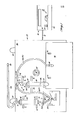
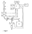
- the present inventive apparatus comprises control unit 20, collection uniti 30, and a signal cable 18 coupled therebetween.
- the collection unit 30 includes a backboard 32 and a plurality of hooks 34 mounted to an upper edge of backboard 32. Hooks 34 are adapted to be removably placed on any suitable horizontal bar or bed frame for suspension support of unit 30.
- a catheter coupler 35 is provided for coupling a standard state of the art medical urinary catheter (not shown) to input tube 36 of unit 30.
- Input tube 36 passes through antireflux valve 38 and then into measurement column 40.
- Measurement column 40 is fixed to backboard 32 by column clamps 46, and lies in a substantially vertical orientation when backboard 32 is appropriately suspended for use.
- tube 36(a) passes through peristaltic pump 50 to output valve 70.
- Output valve 70 serves to route the urinary output to either a collection bag 90 or sample bottle 80.
- the collection bag 90 is removably coupled to backboard 32 by bag hooks 92 as is well known in the art.
- Tube 36(b) is coupled to bag 90 through bag coupler 88, also well known in the art, so that a full collection bag 90 may be removed and replaced without spillage from tube 36(b).
- an optical sensor comprising light source 41 and photodetector 43.
- Light source 41 and photodetector 43 are oriented so that light from light source 41 passes through measurement column 40 and strikes photodetector 43.
- Light source 42 and photodetector 44 are likewise mounted on backboard 32 adjacent to the bottom of measurement column 40, and are oriented so that light from light source 42 passes through measurement column 40 and strikes photodetector 44.
- the frequency-of light transmitted by light sources 41 and 42 is chosen so as to pass through an empty column 40 but be blocked by a full column.
- sample bottle 80 which is removably placed in snap clamps 78 fixed to backboard 32, has light source 82 and photodetector 84 mounted on backboard 32 on opposite sides of sample bottle 80 adjacent the top thereof.
- Bottle 80 is also vertically oriented when backboard 32 is appropriately suspended, and light from light source 82 will pass through bottle 80 to photodetector 84 until bottle 80 is full.
- a cap holder 87 may be fixed to backboard 32 adjacent bottle 80 for retention of the bottle cap 85 until bottle 80 is removed for analysis.
- the ouput of pump 50 may be coupled directly to bag coupler 88, omitting valve 70, bottle 80, light source 82, photodetector 84, clamps 78, bottle cap 85, holder 87 and interlock switch 86.
- Valve 70 comprises a T intersection 72, pinch blocks 74 and 75 adjacent the two tubes 36(c) and 36(b) downstream from intersection 72, and rotatable pinch bar 76.
- Bar 76 is rotated about pivot point 77 by a standard well known device such as a solenoid (not shown) which may be mounted on the reverse side of backboard 32.
- Bar 76 is shown pinching the tube 36(c) which leads to bottle 80 against block 74. This effectively seals tube 36(c) and forces the output of pump 50 to be directed to bag 90.
- Control unit 20 may include digital display 22, printer 24, alarm 23, control input 28, clock 26, and control logic 21 housed advantageously in one compact housing 25.
- Control input 28 may include manual switches such as sample collection switch 27 and master power switch 29.
- Control logic may advantageously comprise any standard microprocessor, such as a type 6502, with appropriate read only memory and random access memory attached, although hardwired logic designs may serve equally effectively.
- valve 70 normally: routes the ouput to bag 90. However, under predetermined conditions such as specific input from control 28, the output may be routed by valve 70 to specimen bottle 80. Control logic 21 will terminate the filling of bottle 80 by resetting valve 70 when photodetector 84 indicates that bottle 80 is full. When photodetector 44 indicates that measurement column 40 is empty, control logic 21 shuts down pump 50 until the predetermined time interval again passes.
- the use of an optical sensor means such as light source 82 and photodetector 84 allows the use of specimen bottles 80 of any size. Alternatively, if a bottle 80 of a single standard size is used, light source 82 and photodetector 84 may be omitted; control logic 21 then determines the point at which bottle 80 is full, based on the known flow rate of pump 50.
- measurement tube 40 may fill up prior to the passage of the predetermined time interval. If this occurs, the signal from photodetector 43 will inform control logic 21 to operate pump 50 until the column is again empty as indicated by photodetector 44.
- Control logic 21 again uses the time taken to empty column 40 or signals from sensor 51 to determine the amount of urinary output involved, and may display this event together with the time as previously described on display 22 and printer 24, and can also activate alarm 23 informing medical personnel of the situation.
- Control logic 21 also maintains a running total of urinary output routed to bag 90, so that alarm 23 may inform medical personnel when bag 90 is full.
- Alarm 23 may consist of, for instance, local audio outputs or remote transmissions to a nurses station, both of which are well known in the art.
- Digital display 22 may be configured to display a variety of information either simultaneously or sequentially under automatic control, or sequentially under manual control. This information may include the current time of day, the volume of urinary output in the previous predetermined time interval, and the total volume currently collected in bag 90.
- the control input 28 may include either local or remote manual controls for power to the system, specimen collection information to be displayed on the digital display 22, and length of the aforementioned predetermined time interval.
- the dimensions of the light beam projected by light sources 41, 42, and 82 should be substantially less than the diameter of column 40 or bottle 80. This will allow the light to be projected through one side of these containers and the output of tube 36 to be directed down another side of the containers, thus preventing accidental tripping of photodetectors 43, 44 or 84 by fluid flow rather than accumulated output.
- the pump 50 includes a frame 60, a rotating disc 52, a portion of tubing 36Ia), and a U-shaped pressure ring member 56.
- Disc 52 is driven on axle 53 by any well-known motor (not shown) which may be mounted, for instance, on the reverse side of backboard 32.
- a motor not shown
- Pressure ring member 56 in Figure 3, encompasses a portion of main disc 52.
- the extremities of ring 56 define channels 57 facing disc 52, the channels being sufficiently wide to hold but not constrict tube 36(a).
- Ring 56 is coupled at pivot point 68 to arm 67, and the other end of arm 67 is coupled at pivot point 69 to hand 65.
- Handle 65 is rotatable about fixed pivot point 66 and may be used to engage or disengage ring 56 with tube 36(a) and disc 52. As shown in figure 3, ring 56 is in a fully engaged position and handle 65 is blocked from further counterclockwise rotation by stop pin 64 mounted to pump frame 60.
- handle 65 has been rotated clockwise until stopped by contact with ring 56.
- Ring extensions 58 which extend outward from ring member 56 slidably engage side rails 63 of frame 60 to ilign the motion of ring member 56 pulled by handle 65.
- the ends of ring member 56 are positioned adjacent top sail 61 of frame 60 and tube 36(a) enters and exits the pump 50 between the aforementioned channels 57 and channels 62 defined in the ends of top rail 61 adjacent channels 57.
- the tube 36(a) passes between ring nember 56 and disc 52, and is constricted by pressure of rollers 54 against the ring member 56 so that the flow of fluid through the tube is blocked.
- the passage of rollers 54 along tube 36(a) force equal pulses of fluid through the pump, although the fluid actually comes in contact only with tube 36(a).
- a variety of equally useful alternative peristaltic pumps are available off-the-shelf including, for instance, Model 200 from Roll-Flex Industries of Elgin, Illinois.
- tube 36(a) When ring member 56 is disengaged from tube 36(a) as shown in Figure 4, pump 50 is disabled and tube 36(a) may be removed therefrom for cleaning or replacement.
- the entire unit 30 is modular and tube 36 (a), (b), (c) and various other components can be connected and disconnected at connectors 37. This allows quick replacement of faulty components and easy disassembly for cleaning and sterilization before use of the inventive system with a new patient.
- the present invention provides efficient collection and measurement of urinary output without the need for frequent patient monitoring by trained personnel and without the dangers and disadvantages inherent in electrical contact between the urine and prior art measurement systems.
- the use of a peristaltic pump and optical measurement means ensures that only the catheter and tubing contacts the urine, thus reducing potential sources of contamination to a minimum.
- the use of adhesive paper in a printer produces a histroical record of the patient's condition which is readily compatible with other human-readable records maintained in modern health care administration practice.
- the use of alarms allows attention to the patient or the invention by trained personnel whenever necessary rather than on a fixed, excessively redundant and wasteful schedule.
Landscapes
- Health & Medical Sciences (AREA)
- Life Sciences & Earth Sciences (AREA)
- Physics & Mathematics (AREA)
- Molecular Biology (AREA)
- Animal Behavior & Ethology (AREA)
- Pathology (AREA)
- Engineering & Computer Science (AREA)
- Biomedical Technology (AREA)
- Heart & Thoracic Surgery (AREA)
- Medical Informatics (AREA)
- Veterinary Medicine (AREA)
- Surgery (AREA)
- Biophysics (AREA)
- General Health & Medical Sciences (AREA)
- Public Health (AREA)
- Physiology (AREA)
- Urology & Nephrology (AREA)
- Optics & Photonics (AREA)
- Fluid Mechanics (AREA)
- General Physics & Mathematics (AREA)
- External Artificial Organs (AREA)
- Investigating Or Analysing Biological Materials (AREA)
- Measurement Of Levels Of Liquids Or Fluent Solid Materials (AREA)
Applications Claiming Priority (2)
| Application Number | Priority Date | Filing Date | Title |
|---|---|---|---|
| US06/295,073 US4532936A (en) | 1981-08-21 | 1981-08-21 | Automatic urine flow meter |
| US295073 | 1981-08-21 |
Publications (2)
| Publication Number | Publication Date |
|---|---|
| EP0073156A1 true EP0073156A1 (fr) | 1983-03-02 |
| EP0073156B1 EP0073156B1 (fr) | 1986-04-23 |
Family
ID=23136096
Family Applications (1)
| Application Number | Title | Priority Date | Filing Date |
|---|---|---|---|
| EP82304426A Expired EP0073156B1 (fr) | 1981-08-21 | 1982-08-23 | Appareil pour la mesure et la réception automatiques de l'écoulement urinaire d'un patient |
Country Status (5)
| Country | Link |
|---|---|
| US (1) | US4532936A (fr) |
| EP (1) | EP0073156B1 (fr) |
| JP (1) | JPS5846960A (fr) |
| CA (1) | CA1188541A (fr) |
| DE (1) | DE3270764D1 (fr) |
Cited By (1)
| Publication number | Priority date | Publication date | Assignee | Title |
|---|---|---|---|---|
| DE4338687C1 (de) * | 1993-11-12 | 1995-07-06 | Fresenius Ag | Urinmeßgerät und Verfahren zum Ermitteln der Dichte von Urin |
Families Citing this family (53)
| Publication number | Priority date | Publication date | Assignee | Title |
|---|---|---|---|---|
| SE8206430L (sv) * | 1982-11-12 | 1984-05-13 | Meteve Ab | Anordning for urinmetning |
| US4658834A (en) * | 1983-03-16 | 1987-04-21 | C.R. Bard, Inc. | Medical apparatus for monitoring body liquid discharge |
| JPS6034428A (ja) * | 1983-08-05 | 1985-02-22 | オリンパス光学工業株式会社 | 内視鏡用光源装置 |
| EP0232263A4 (fr) * | 1984-04-10 | 1988-06-23 | Bioflow Inc | Moniteur de niveau de liquide et d'ecoulement d'urine. |
| JPS60219986A (ja) * | 1984-04-17 | 1985-11-02 | Shinko Electric Co Ltd | 誘導電動機制御装置 |
| US4922922A (en) * | 1988-04-12 | 1990-05-08 | Pollock Richard A | Fluid monitoring apparatus |
| US4891993A (en) * | 1988-09-30 | 1990-01-09 | Prevention Sciences Incorporated | Apparatus and method for measurement of urine void volumes |
| US5226313A (en) * | 1989-12-15 | 1993-07-13 | Murata Mfg. Co., Ltd. | Body fluid excretion measurement apparatus for medical application |
| US5037407A (en) * | 1990-03-30 | 1991-08-06 | Bioresearch, Inc. | Electronic monitoring system for drainage device |
| WO1995022999A1 (fr) * | 1994-02-28 | 1995-08-31 | Itec Co., Ltd. | Dispositif unitaire de mesure de la miction |
| US5629498A (en) * | 1995-01-18 | 1997-05-13 | Richard A. Pollock | Intraoperative tracking devices and processes |
| AU4967596A (en) * | 1995-02-07 | 1996-09-04 | Gensia, Inc. | Feedback controlled drug delivery system |
| US5596150A (en) * | 1995-03-08 | 1997-01-21 | The United States Of America As Represented By The Administrator Of The National Aeronautics And Space Administration | Capacitance probe for fluid flow and volume measurements |
| US5704923A (en) * | 1995-08-31 | 1998-01-06 | Chiu-Hsiung; Chiang | Liquid level detector and alarm device for drip infusion sets |
| US5836909A (en) * | 1996-09-13 | 1998-11-17 | Cosmescu; Ioan | Automatic fluid control system for use in open and laparoscopic laser surgery and electrosurgery and method therefor |
| US6012181A (en) * | 1998-08-10 | 2000-01-11 | Quality Assistive Devices, Incorporated | System for draining a urinary drainage container |
| GB9824333D0 (en) * | 1998-11-07 | 1998-12-30 | Griffiths Clive J | Non-invasive bladder pressure measurements |
| IL128056A (en) | 1999-01-14 | 2005-11-20 | S F M Sophisticated Water Mete | Liquid metering device |
| AT500492B1 (de) * | 1999-03-24 | 2007-02-15 | Basta Walter O | Rechnerunterstütztes system zur patientenüberwachung |
| FI110305B (fi) * | 2000-02-17 | 2002-12-31 | Instrumentarium Oyj | Sovitelma potilasvalvontamonitorin yhteydessä |
| NL1022161C2 (nl) * | 2002-12-13 | 2004-06-18 | Karel Hero Mulder | Urologisch instrument voor het beoordelen van een urinestroom. |
| ITBO20030091A1 (it) * | 2003-02-25 | 2004-08-26 | Antonio Tucci | Procedimento per l'identificazione rapida di infezioni e/o di situazioni a rischio di patologie gastroduodenali e macchina per attuare il procedimento. |
| ATE354311T1 (de) * | 2004-05-07 | 2007-03-15 | Transmed Medizintechnik Gmbh & | Vorrichtung zur automatischen überwachung des flusses einer flüssigkeit, insbesondere urin |
| IL166400A (en) * | 2005-01-20 | 2012-07-31 | Flowsense Ltd | Optical drop detection system |
| US7892217B2 (en) * | 2005-04-10 | 2011-02-22 | Future Path Medical, Llc | Variable cross-section containment structure liquid measurement device |
| US8813551B2 (en) * | 2005-04-10 | 2014-08-26 | Future Path Medical Holding Co. Llc | Device that accurately measures physiological fluid flow |
| EP2081493A2 (fr) * | 2006-11-14 | 2009-07-29 | Med-I-Dynamix Fluid Monitoring Ltd. | Procédé et appareil de diagnostic |
| EP2086846A4 (fr) * | 2006-11-29 | 2012-01-25 | Future Path Medical Llc | Contenant pour fluides physiologiques |
| IL185477A0 (en) | 2007-08-23 | 2008-01-06 | Med I Dynamix Fluid Monitoring | Diagnostic methods and systems based on urine analysis |
| WO2009029551A1 (fr) | 2007-08-25 | 2009-03-05 | Beckersmith Medical, Inc. | Appareil et procédé de régulation automatisée de drainage de liquide organique |
| WO2010141458A2 (fr) * | 2009-06-03 | 2010-12-09 | Biometrix Ltd | Appareil et procédé pour la collecte au chevet du lit des fluides corporels et la surveillance automatique du volume |
| US8276465B2 (en) | 2010-06-10 | 2012-10-02 | Edward Belotserkovsky | Urine flow monitoring device and method |
| CN107205675B (zh) * | 2014-09-28 | 2020-06-30 | 波特雷罗医疗公司 | 用于感测生理数据以及引流和分析体液的系统、设备和方法 |
| CN104914261A (zh) * | 2015-05-27 | 2015-09-16 | 宗有莲 | 妇产科尿液检查装置 |
| WO2017023794A1 (fr) | 2015-07-31 | 2017-02-09 | Medivance Incorporated | Système de collecte et de surveillance du débit urinaire |
| US10072962B2 (en) | 2016-07-05 | 2018-09-11 | Ecolab Usa Inc. | Liquid out-of-product alarm system and method |
| US11617568B2 (en) | 2016-12-29 | 2023-04-04 | Jay K. Joshi | Fluid output measurement device and method |
| EP4252816A3 (fr) | 2018-05-22 | 2024-01-17 | C. R. Bard, Inc. | Système de cathétérisme et procédés pour son utilisation |
| WO2020033752A1 (fr) | 2018-08-10 | 2020-02-13 | C. R. Bard, Inc. | Systèmes automatisés de mesure de sortie d'urine et procédés associés |
| EP3846737B1 (fr) * | 2018-09-07 | 2022-11-09 | Coloplast A/S | Dispositif de mesure de volume de liquide |
| US12083261B2 (en) | 2020-06-05 | 2024-09-10 | C. R. Bard, Inc. | Automated fluid output monitoring |
| US11703365B2 (en) | 2020-07-14 | 2023-07-18 | C. R. Bard, Inc. | Automatic fluid flow system with push-button connection |
| US12055249B2 (en) | 2020-07-21 | 2024-08-06 | C. R. Bard, Inc. | Automatic fluid flow system with retractable connection |
| JP7657913B2 (ja) * | 2020-08-19 | 2025-04-07 | オーグメント ヘルス インコーポレイテッド | 尿道カテーテルシステムおよび方法 |
| WO2022108589A1 (fr) | 2020-11-19 | 2022-05-27 | C.R. Bard, Inc. | Système de réponse à la pression dynamique |
| US12408853B2 (en) | 2020-12-17 | 2025-09-09 | C. R. Bard, Inc. | Smart bag to measure urine output via catheter |
| US12364423B2 (en) | 2020-12-21 | 2025-07-22 | C. R. Bard, Inc. | Automated urinary output-measuring systems and methods |
| US11931151B2 (en) | 2020-12-22 | 2024-03-19 | C. R. Bard, Inc. | Automated urinary output measuring system |
| US12246146B2 (en) | 2020-12-23 | 2025-03-11 | C. R. Bard, Inc. | Automated weight based fluid output monitoring system |
| EP4297649A1 (fr) | 2021-02-23 | 2024-01-03 | C. R. Bard, Inc. | Systèmes et méthodes de surveillance de la vessie non invasive et à auto-apprentissage |
| JPWO2022209703A1 (fr) * | 2021-03-31 | 2022-10-06 | ||
| US12446813B2 (en) | 2021-08-23 | 2025-10-21 | C. R. Bard, Inc. | Automated urine output system for attachment to hospital bed |
| WO2023148435A1 (fr) * | 2022-02-04 | 2023-08-10 | Sorbonne Universite | Dispositif de suivi de la miction d'un patient |
Citations (7)
| Publication number | Priority date | Publication date | Assignee | Title |
|---|---|---|---|---|
| DE2162998A1 (de) * | 1971-12-18 | 1973-06-20 | Siegfried Klusch | Peristaltik-schlauchpumpe fuer extracorporale blutkreislaeufe |
| US3818895A (en) * | 1971-11-01 | 1974-06-25 | J Stewart | Oligaemic shock assessment apparatus |
| US3838691A (en) * | 1972-02-25 | 1974-10-01 | Pharma Plasto Pty Ltd | Catheter device |
| FR2239981A1 (fr) * | 1973-08-09 | 1975-03-07 | Int Paper Co | |
| FR2258870A1 (en) * | 1974-01-25 | 1975-08-22 | Bioengineering Research | Medical dosage electronic control unit providing constant output - has digital counters dosage keyboard and injection tube monitor |
| DE2754809A1 (de) * | 1977-12-09 | 1979-06-13 | Fresenius Chem Pharm Ind | Vorrichtung zur periodischen spuelung von koerperhoehlen, insbesondere der bauchhoehle |
| WO1980002376A1 (fr) * | 1979-04-30 | 1980-11-13 | E Lichtenstein | Systeme de soins medicaux controles par ordinateur |
Family Cites Families (3)
| Publication number | Priority date | Publication date | Assignee | Title |
|---|---|---|---|---|
| US3769497A (en) * | 1971-09-10 | 1973-10-30 | Hoffmann La Roche | Urine liquid discharge monitor |
| US4343316A (en) * | 1980-05-16 | 1982-08-10 | C. R. Bard, Inc. | Electronic urine flow monitor |
| US4381776A (en) * | 1980-06-20 | 1983-05-03 | Haemonetics Corporation | Anticoagulant dispensing apparatus and method of use |
-
1981
- 1981-08-21 US US06/295,073 patent/US4532936A/en not_active Expired - Fee Related
-
1982
- 1982-08-19 CA CA000409761A patent/CA1188541A/fr not_active Expired
- 1982-08-20 JP JP57145403A patent/JPS5846960A/ja active Pending
- 1982-08-23 EP EP82304426A patent/EP0073156B1/fr not_active Expired
- 1982-08-23 DE DE8282304426T patent/DE3270764D1/de not_active Expired
Patent Citations (7)
| Publication number | Priority date | Publication date | Assignee | Title |
|---|---|---|---|---|
| US3818895A (en) * | 1971-11-01 | 1974-06-25 | J Stewart | Oligaemic shock assessment apparatus |
| DE2162998A1 (de) * | 1971-12-18 | 1973-06-20 | Siegfried Klusch | Peristaltik-schlauchpumpe fuer extracorporale blutkreislaeufe |
| US3838691A (en) * | 1972-02-25 | 1974-10-01 | Pharma Plasto Pty Ltd | Catheter device |
| FR2239981A1 (fr) * | 1973-08-09 | 1975-03-07 | Int Paper Co | |
| FR2258870A1 (en) * | 1974-01-25 | 1975-08-22 | Bioengineering Research | Medical dosage electronic control unit providing constant output - has digital counters dosage keyboard and injection tube monitor |
| DE2754809A1 (de) * | 1977-12-09 | 1979-06-13 | Fresenius Chem Pharm Ind | Vorrichtung zur periodischen spuelung von koerperhoehlen, insbesondere der bauchhoehle |
| WO1980002376A1 (fr) * | 1979-04-30 | 1980-11-13 | E Lichtenstein | Systeme de soins medicaux controles par ordinateur |
Cited By (1)
| Publication number | Priority date | Publication date | Assignee | Title |
|---|---|---|---|---|
| DE4338687C1 (de) * | 1993-11-12 | 1995-07-06 | Fresenius Ag | Urinmeßgerät und Verfahren zum Ermitteln der Dichte von Urin |
Also Published As
| Publication number | Publication date |
|---|---|
| DE3270764D1 (en) | 1986-05-28 |
| EP0073156B1 (fr) | 1986-04-23 |
| US4532936A (en) | 1985-08-06 |
| JPS5846960A (ja) | 1983-03-18 |
| CA1188541A (fr) | 1985-06-11 |
Similar Documents
| Publication | Publication Date | Title |
|---|---|---|
| EP0073156B1 (fr) | Appareil pour la mesure et la réception automatiques de l'écoulement urinaire d'un patient | |
| US4654029A (en) | Electronic drainage system | |
| US4343316A (en) | Electronic urine flow monitor | |
| US8337476B2 (en) | Real time urine monitoring system | |
| EP3422948B1 (fr) | Appareil de pesage d'urine | |
| AU772647B2 (en) | Directly engaged syringe driver system | |
| US6640649B1 (en) | Droplet counter for low flow rates | |
| US3769497A (en) | Urine liquid discharge monitor | |
| CN103637811A (zh) | 一种医用尿流量动态检测仪 | |
| CN203852362U (zh) | 一种医用尿流量动态检测仪 | |
| CN104939846A (zh) | 一种动态尿液计量仪 | |
| WO2022009223A1 (fr) | Système et procédé destinés à surveiller la sortie d'urine | |
| CN2296731Y (zh) | 病房输液监控系统 | |
| EP0109373A2 (fr) | Dispositif pour la mesure d'urine | |
| US20260115035A1 (en) | A fluid collection device | |
| US20220296141A1 (en) | Fluid collection systems and methods and collecting fluids | |
| CN209004987U (zh) | 一种医用的导尿装置 | |
| WO2000065313A1 (fr) | Debitmetre | |
| LU603664B1 (en) | Apparatus for detecting and metering urine discharge | |
| CN223529721U (zh) | 输液指示条 | |
| WO2024246478A1 (fr) | Appareil de surveillance de l'écoulement d'urine | |
| KR20250163005A (ko) | 배뇨 채집시스템 | |
| IE58296B1 (en) | Electronic drainage system |
Legal Events
| Date | Code | Title | Description |
|---|---|---|---|
| PUAI | Public reference made under article 153(3) epc to a published international application that has entered the european phase |
Free format text: ORIGINAL CODE: 0009012 |
|
| AK | Designated contracting states |
Designated state(s): BE DE FR GB LU NL |
|
| 17P | Request for examination filed |
Effective date: 19830405 |
|
| GRAA | (expected) grant |
Free format text: ORIGINAL CODE: 0009210 |
|
| AK | Designated contracting states |
Kind code of ref document: B1 Designated state(s): BE DE FR GB LU NL |
|
| PG25 | Lapsed in a contracting state [announced via postgrant information from national office to epo] |
Ref country code: NL Effective date: 19860423 Ref country code: FR Free format text: THE PATENT HAS BEEN ANNULLED BY A DECISION OF A NATIONAL AUTHORITY Effective date: 19860423 Ref country code: BE Effective date: 19860423 |
|
| REF | Corresponds to: |
Ref document number: 3270764 Country of ref document: DE Date of ref document: 19860528 |
|
| PG25 | Lapsed in a contracting state [announced via postgrant information from national office to epo] |
Ref country code: LU Free format text: LAPSE BECAUSE OF NON-PAYMENT OF DUE FEES Effective date: 19860831 |
|
| EN | Fr: translation not filed | ||
| NLV1 | Nl: lapsed or annulled due to failure to fulfill the requirements of art. 29p and 29m of the patents act | ||
| PLBE | No opposition filed within time limit |
Free format text: ORIGINAL CODE: 0009261 |
|
| STAA | Information on the status of an ep patent application or granted ep patent |
Free format text: STATUS: NO OPPOSITION FILED WITHIN TIME LIMIT |
|
| 26N | No opposition filed | ||
| PG25 | Lapsed in a contracting state [announced via postgrant information from national office to epo] |
Ref country code: DE Effective date: 19880503 |
|
| GBPC | Gb: european patent ceased through non-payment of renewal fee | ||
| PG25 | Lapsed in a contracting state [announced via postgrant information from national office to epo] |
Ref country code: GB Free format text: LAPSE BECAUSE OF NON-PAYMENT OF DUE FEES Effective date: 19881121 |