EP0073232B1 - Procede et dispositif de pulverisation d'un liquide ou d'une suspension - Google Patents
Procede et dispositif de pulverisation d'un liquide ou d'une suspension Download PDFInfo
- Publication number
- EP0073232B1 EP0073232B1 EP82900942A EP82900942A EP0073232B1 EP 0073232 B1 EP0073232 B1 EP 0073232B1 EP 82900942 A EP82900942 A EP 82900942A EP 82900942 A EP82900942 A EP 82900942A EP 0073232 B1 EP0073232 B1 EP 0073232B1
- Authority
- EP
- European Patent Office
- Prior art keywords
- disk
- liquid
- spray cone
- spraying
- disk section
- Prior art date
- Legal status (The legal status is an assumption and is not a legal conclusion. Google has not performed a legal analysis and makes no representation as to the accuracy of the status listed.)
- Expired
Links
Images

Classifications
-
- B—PERFORMING OPERATIONS; TRANSPORTING
- B05—SPRAYING OR ATOMISING IN GENERAL; APPLYING FLUENT MATERIALS TO SURFACES, IN GENERAL
- B05B—SPRAYING APPARATUS; ATOMISING APPARATUS; NOZZLES
- B05B3/00—Spraying or sprinkling apparatus with moving outlet elements or moving deflecting elements
- B05B3/02—Spraying or sprinkling apparatus with moving outlet elements or moving deflecting elements with rotating elements
- B05B3/10—Spraying or sprinkling apparatus with moving outlet elements or moving deflecting elements with rotating elements discharging over substantially the whole periphery of the rotating member
- B05B3/1007—Spraying or sprinkling apparatus with moving outlet elements or moving deflecting elements with rotating elements discharging over substantially the whole periphery of the rotating member characterised by the rotating member
-
- F—MECHANICAL ENGINEERING; LIGHTING; HEATING; WEAPONS; BLASTING
- F26—DRYING
- F26B—DRYING SOLID MATERIALS OR OBJECTS BY REMOVING LIQUID THEREFROM
- F26B3/00—Drying solid materials or objects by processes involving the application of heat
- F26B3/02—Drying solid materials or objects by processes involving the application of heat by convection, i.e. heat being conveyed from a heat source to the materials or objects to be dried by a gas or vapour, e.g. air
- F26B3/10—Drying solid materials or objects by processes involving the application of heat by convection, i.e. heat being conveyed from a heat source to the materials or objects to be dried by a gas or vapour, e.g. air the gas or vapour carrying the materials or objects to be dried with it
- F26B3/12—Drying solid materials or objects by processes involving the application of heat by convection, i.e. heat being conveyed from a heat source to the materials or objects to be dried by a gas or vapour, e.g. air the gas or vapour carrying the materials or objects to be dried with it in the form of a spray, i.e. sprayed or dispersed emulsions or suspensions
Definitions
- the invention relates to a method for spraying a liquid or suspension by throwing off a spray cone of small droplets from a rotating centrifugal disc, and to a corresponding spray device with a drive shaft which can be set in rapid rotation by a drive device, at least one spray head arranged in a rotationally fixed manner with an essentially conical one Casing surface arranged throwing edge and a rotor connected to the spray head for common rotation.
- the diameter of the spray cone produced is influenced by the diameter of the centrifugal disc and its speed.
- a very uniform droplet size of, for example, 35 it can be achieved the hollow cone produced during spraying has a relatively large diameter of, for example, 100 to 120 cm, which is undesirable for many applications.
- an electrostatic paint spray gun of the type mentioned in which the spray head has a non-rotatably connected hub to a motor shaft, a conical lateral surface connected to it only by three radial arms with a flinging edge and an outside charging edge the hub is fitted with an axial fan with the conveying direction towards the workpiece and the paint mist sprayed from the centrifugal edge is deflected towards the workpiece by an axial air flow passing over the spray head on the outside. Since in this device, which works with compressed air supply and electrostatic voltage, the air moved by the axial fan in the direction of the workpiece is inevitably deflected outward in front of the workpiece, this results in an undesirable widening of the spray cone.
- a similar spray device in which a compressed air jet is permanently blown axially into the interior of a spray cone thrown from the flinging edge of a conical lateral surface through an air nozzle and a ring of bores in the direction of the workpiece.
- the blown-in compressed air has to leave the interior of the spray cone somewhere, which in turn leads to a radially outward air flow and a consequent widening of the spray cone.
- the object of the invention is to provide a method for spraying a liquid or suspension, a corresponding spraying device or a suitable centrifugal disc, which enables the production of a spray cone of smaller diameter in a simple manner without impairing the uniformity and the fineness of the droplet size achieved.
- the invention further relates to a spray device of the type mentioned at the outset, which is characterized by the features of patent claim 3.
- the invention also includes a centrifugal disc for a spray device according to the preamble of claim 3, which is equipped with the features of claim 7.
- the method and the spray device make it possible to reduce the diameter of the spray cone produced in a simple, uncomplicated manner without impairing the fineness and the uniformity of the droplet size.
- a centrifugal disc with an outer diameter of 5 cm can be used to produce a spray cone with a diameter of only 25 to 35 cm without impairing the fineness and uniformity of the droplet size.
- the method according to the invention and the spray devices according to the invention are particularly suitable where areas of relatively small dimensions are to be treated without the undesirable spraying of neighboring areas. This is the case, for example, when spraying goods moving on a relatively narrow conveyor belt, the diameter of the spray cone not to exceed the width of the conveyor belt.
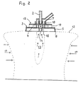
- the spray device shown in Fig. 1 has a battery-powered drive motor 1, on the drive shaft 2, a centrifugal disc 3 is releasably attached.
- the centrifugal disc 3 has a substantially radially blue color Fenden disc section 4 and an obliquely angled edge skirt 5 on its outer edge, the outer spray edge 6 is formed in a manner known per se fine sawtooth-like (tooth width about 0.5 mm), which is not shown in the drawings for reasons of clarity.
- a propeller 10 is arranged, which is detachably connected to the centrifugal disc 3 and carries a plurality of propeller blades 11, which are shaped and aligned so that the propeller 10 when it rotates together with the The centrifugal disc 3 generates an air flow directed axially towards it and a vacuum zone 13 is formed on the vacuum side of the propeller 10 facing away from the centrifugal disc 3.
- a feed channel 7 for the spraying liquid is arranged in a stationary manner around the drive shaft 2.
- the liquid supplied by this is prevented by the annular apron 18 arranged on the centrifugal disk 3 from radially escaping and passes through through openings 8 arranged near the axis of the disk section 4 to the side of the disk section 4 facing the propeller 10, from where it occurs under the action of the centrifugal force the inner surface of the edge apron 5 is moved up to its sawtooth-like serrated spray edge 6 and is then thrown off by its pointed protrusions in the form of thin liquid jets that immediately disintegrate into droplets of practically the same size.
- the liquid droplets thrown off move radially outward under the action of the centrifugal force and at the same time fall down under the action of gravity, so that a hollow spray cone 12 is formed.
- an impeller 15 is provided on the centrifugal disc 3 instead of the propeller 10, which is arranged on the side facing away from the spray cone 12 and rotates with the centrifugal disc 3 and with its impeller blades 19 the air lying therebetween radially outwards Accelerated and thus constantly sucks air through the suction opening 14 communicating with the interior of the spray cone 12, so that a negative pressure zone 13 is formed there, which in turn causes a centripetal flow 17 directed towards this and thus a narrowing of the diameter of the spray cone 12 generated.
- passage channels 16 are provided which are arranged at uniform intervals over the circumference.
- gas passage openings 9 can be provided in the disc section 4 of the centrifugal disc 3 distributed over its circumference. These are expediently designed by inclined design of their walls so that the liquid to be sprayed is prevented from escaping through the gas passage openings 9. In certain cases, however, it may also be desirable to allow a portion of the liquid supplied to pass onto the outer surface of the centrifugal disc 3 by appropriately designing the gas passage openings. This applies in particular if it is provided there with a second edge apron 5 (not shown).
- the spray device explained above with reference to preferred embodiments can be modified by the person skilled in the art in various ways depending on the requirements of the individual case, provided that the use of a rotor for generating a vacuum zone 13 lying inside the spray cone 12 and a centripetal flow 17 is maintained.
- the diameter of the centrifugal disc 3, the design and the dimensions of the skirt 5, the propeller 10 or the impeller 15 and the arrangement and size of the passage openings 8 and any gas passage openings 9 should be based on the type and flow properties of the liquid or suspension to be sprayed Desired droplet size and the desired diameter of the spray cone 12 can be adjusted appropriately.
- the centrifugal disc is fastened in the usual way, for example by a clamping screw or by means of a thread on the drive shaft.
Landscapes
- Engineering & Computer Science (AREA)
- Life Sciences & Earth Sciences (AREA)
- Microbiology (AREA)
- Mechanical Engineering (AREA)
- General Engineering & Computer Science (AREA)
- Nozzles (AREA)
Claims (8)
Priority Applications (1)
| Application Number | Priority Date | Filing Date | Title |
|---|---|---|---|
| AT82900942T ATE17194T1 (de) | 1981-03-05 | 1982-02-27 | Verfahren und vorrichtung zum verspruehen einer fluessigkeit oder suspension. |
Applications Claiming Priority (2)
| Application Number | Priority Date | Filing Date | Title |
|---|---|---|---|
| DE3108292 | 1981-03-05 | ||
| DE3108292A DE3108292C2 (de) | 1981-03-05 | 1981-03-05 | Verfahren und Vorrichtung zum Versprühen einer Flüssigkeit oder Suspension |
Publications (2)
| Publication Number | Publication Date |
|---|---|
| EP0073232A1 EP0073232A1 (fr) | 1983-03-09 |
| EP0073232B1 true EP0073232B1 (fr) | 1986-01-02 |
Family
ID=6126385
Family Applications (1)
| Application Number | Title | Priority Date | Filing Date |
|---|---|---|---|
| EP82900942A Expired EP0073232B1 (fr) | 1981-03-05 | 1982-02-27 | Procede et dispositif de pulverisation d'un liquide ou d'une suspension |
Country Status (4)
| Country | Link |
|---|---|
| US (1) | US4562958A (fr) |
| EP (1) | EP0073232B1 (fr) |
| DE (2) | DE3108292C2 (fr) |
| WO (1) | WO1982003026A1 (fr) |
Families Citing this family (9)
| Publication number | Priority date | Publication date | Assignee | Title |
|---|---|---|---|---|
| FR2538795B1 (fr) * | 1982-12-30 | 1987-01-02 | Raffinage Cie Francaise | Perfectionnements aux dispositifs de remplissage d'une enceinte avec un solide sous forme particulaire |
| US5400608A (en) * | 1993-02-05 | 1995-03-28 | Ryan Instruments, L.P. | Humidity control system |
| DE4326714A1 (de) * | 1993-08-03 | 1995-02-09 | Mantis Ulv Spruehgeraete | Segmentrotationsdüse |
| DE10329813B4 (de) | 2003-07-01 | 2006-01-26 | Glatt Systemtechnik Gmbh | Vorrichtung zur Ausbildung von Umhüllungen auf Oberflächen fester Körper in einer Beschichtungskammer |
| USD596905S1 (en) | 2008-01-16 | 2009-07-28 | Sherrard James M | Cup with mist dispensing opening |
| DE102009045797A1 (de) * | 2009-10-19 | 2011-04-21 | Robert Bosch Gmbh | Elektrische Maschine, Hydraulikeinheit |
| IL247361A0 (en) * | 2016-08-18 | 2016-12-29 | Safepack Products Ltd | Spray head with uniform coverage |
| BR112022015337A2 (pt) * | 2020-02-05 | 2022-09-27 | Bayer Ag | Unidade de pulverização |
| CN117732627B (zh) * | 2024-02-21 | 2024-05-14 | 特丝丽化工有限公司 | 一种洗衣粉的喷射装置 |
Family Cites Families (11)
| Publication number | Priority date | Publication date | Assignee | Title |
|---|---|---|---|---|
| NL298385A (fr) * | ||||
| FR551954A (fr) * | 1922-05-23 | 1923-04-18 | & Commerciale Du Midi Soc Ind | Procédé et appareil pour la désinfection et la destruction d'animaux nuisibles aumoyen d'anhydride sulfureux |
| GB288904A (en) * | 1926-08-31 | 1928-04-19 | Hundertfeuer Ges Fuer Moderne | Improvements in liquid spraying devices |
| US1973051A (en) * | 1931-07-09 | 1934-09-11 | Arthur K Doolittle | Atomizing disk |
| DE692808C (de) * | 1937-12-15 | 1940-06-27 | Kohlenscheidungs Ges M B H | Einrichtung zum Trocknen von Gut durch Zerstaeubung |
| GB665655A (en) * | 1949-04-06 | 1952-01-30 | Pest Control Ltd | Device for distributing liquid |
| GB751609A (en) * | 1954-01-15 | 1956-07-04 | Alfons Mauser | Improvements in spraying and atomising nozzles, particularly for plantprotecting media |
| NL283731A (fr) * | 1961-09-27 | |||
| BE642144A (fr) * | 1963-01-28 | 1964-05-04 | ||
| DE1933147A1 (de) * | 1969-06-30 | 1971-01-21 | Mueller Ernst Kg | Farbspritzpistole fuer das elektrostatische Farbspritzen |
| DE2237021A1 (de) * | 1972-07-12 | 1974-01-31 | Grolitsch Erhard Dipl Agr | Vorrichtung zum zerstaeuben von fluessigkeiten |
-
1981
- 1981-03-05 DE DE3108292A patent/DE3108292C2/de not_active Expired
-
1982
- 1982-02-27 DE DE8282900942T patent/DE3268212D1/de not_active Expired
- 1982-02-27 EP EP82900942A patent/EP0073232B1/fr not_active Expired
- 1982-02-27 US US06/438,898 patent/US4562958A/en not_active Expired - Lifetime
- 1982-02-27 WO PCT/EP1982/000041 patent/WO1982003026A1/fr not_active Ceased
Also Published As
| Publication number | Publication date |
|---|---|
| WO1982003026A1 (fr) | 1982-09-16 |
| DE3268212D1 (en) | 1986-02-13 |
| DE3108292A1 (de) | 1982-09-30 |
| US4562958A (en) | 1986-01-07 |
| DE3108292C2 (de) | 1986-05-07 |
| EP0073232A1 (fr) | 1983-03-09 |
Similar Documents
| Publication | Publication Date | Title |
|---|---|---|
| DE69120872T2 (de) | Verbesserungen zu den rotierenden Zerstäubern | |
| DE2837543C2 (de) | Dunstabzugsvorrichtung | |
| DE69306975T2 (de) | Farbspritzvorrichtung mit rotierendem zerstäubungselement und werkzeug zum montieren und demontieren dieses elements | |
| DE69002043T2 (de) | Rotationszerstäuber. | |
| DE3627345A1 (de) | Zentrifugalzerstaeuber | |
| DE2541927C3 (de) | Zerstäuberdüse | |
| EP0073232B1 (fr) | Procede et dispositif de pulverisation d'un liquide ou d'une suspension | |
| DE102012010610A1 (de) | Verfahren zum Betreiben eines Rotationszerstäubers, Düsenkopf und Rotationszerstäuber mit einem solchen | |
| DE2814958A1 (de) | Mikromahlmischer | |
| DE1206335B (de) | Zerstaeuberkopf zum elektrostatischen Zerstaeuben | |
| EP2460591B1 (fr) | Tête de buse et pulvérisateur rotatif doté de celle-ci | |
| EP1917421B1 (fr) | Compresseur, roue de compresseur, accessoire de nettoyage et turbocompresseur d'échappement | |
| US3556400A (en) | Appliance for the electrostatic coating of objects with coating materials in liquid or powder form | |
| EP2143500B1 (fr) | Procédé et pulvérisateur pour le revêtement de pièces en séries | |
| DE2328019A1 (de) | Verfahren und vorrichtung zum granulieren von kunststoffen | |
| DE69731138T2 (de) | Rotierende elektrostatische Sprühvorrichtung | |
| DE1933147A1 (de) | Farbspritzpistole fuer das elektrostatische Farbspritzen | |
| DE3201753A1 (de) | Verfahren und vorrichtung zum aufbringen von fluessiger farbe auf gegenstaende | |
| DE2517716C3 (de) | Rund- oder Ringstrahldfise | |
| DE1162135B (de) | Brennkammer fuer Gasturbinenanlagen | |
| DE3720200A1 (de) | Spruehbeschichtungseinrichtung mit einem rotationsspruehorgan | |
| DE19935253A1 (de) | Elektrostatischer Rotationszerstäuber | |
| DE19721615A1 (de) | Vorrichtung mit mindestens einem rotierbar gelagerten Hohlkörper | |
| DE911116C (de) | Fluessigkeitszerstaeuber | |
| EP0727282A1 (fr) | Dispositif et procédé pour de sablage pour des parois d'alésages ou de tubes |
Legal Events
| Date | Code | Title | Description |
|---|---|---|---|
| PUAI | Public reference made under article 153(3) epc to a published international application that has entered the european phase |
Free format text: ORIGINAL CODE: 0009012 |
|
| 17P | Request for examination filed |
Effective date: 19821102 |
|
| AK | Designated contracting states |
Designated state(s): AT BE CH DE FR GB LI LU NL SE |
|
| GRAA | (expected) grant |
Free format text: ORIGINAL CODE: 0009210 |
|
| RAP1 | Party data changed (applicant data changed or rights of an application transferred) |
Owner name: MANTIS ULV-SPRUEHGERAETE GMBH |
|
| AK | Designated contracting states |
Designated state(s): AT BE CH DE FR GB LI LU NL SE |
|
| REF | Corresponds to: |
Ref document number: 17194 Country of ref document: AT Date of ref document: 19860115 Kind code of ref document: T |
|
| REF | Corresponds to: |
Ref document number: 3268212 Country of ref document: DE Date of ref document: 19860213 |
|
| ET | Fr: translation filed | ||
| PG25 | Lapsed in a contracting state [announced via postgrant information from national office to epo] |
Ref country code: LU Free format text: LAPSE BECAUSE OF NON-PAYMENT OF DUE FEES Effective date: 19860228 |
|
| PLBE | No opposition filed within time limit |
Free format text: ORIGINAL CODE: 0009261 |
|
| STAA | Information on the status of an ep patent application or granted ep patent |
Free format text: STATUS: NO OPPOSITION FILED WITHIN TIME LIMIT |
|
| 26N | No opposition filed | ||
| PG25 | Lapsed in a contracting state [announced via postgrant information from national office to epo] |
Ref country code: DE Effective date: 19881101 |
|
| PGFP | Annual fee paid to national office [announced via postgrant information from national office to epo] |
Ref country code: SE Payment date: 19890216 Year of fee payment: 8 |
|
| PGFP | Annual fee paid to national office [announced via postgrant information from national office to epo] |
Ref country code: LU Payment date: 19890222 Year of fee payment: 8 |
|
| PGFP | Annual fee paid to national office [announced via postgrant information from national office to epo] |
Ref country code: AT Payment date: 19890223 Year of fee payment: 8 |
|
| PGFP | Annual fee paid to national office [announced via postgrant information from national office to epo] |
Ref country code: BE Payment date: 19890405 Year of fee payment: 8 |
|
| PGFP | Annual fee paid to national office [announced via postgrant information from national office to epo] |
Ref country code: CH Payment date: 19890510 Year of fee payment: 8 |
|
| PG25 | Lapsed in a contracting state [announced via postgrant information from national office to epo] |
Ref country code: AT Effective date: 19900227 |
|
| PG25 | Lapsed in a contracting state [announced via postgrant information from national office to epo] |
Ref country code: SE Effective date: 19900228 Ref country code: LI Effective date: 19900228 Ref country code: CH Effective date: 19900228 Ref country code: BE Effective date: 19900228 |
|
| BERE | Be: lapsed |
Owner name: MANTIS ULV-SPRUHGERATE G.M.B.H. Effective date: 19900228 |
|
| REG | Reference to a national code |
Ref country code: CH Ref legal event code: PL |
|
| PGFP | Annual fee paid to national office [announced via postgrant information from national office to epo] |
Ref country code: FR Payment date: 19931231 Year of fee payment: 13 |
|
| EUG | Se: european patent has lapsed |
Ref document number: 82900942.2 Effective date: 19901107 |
|
| PGFP | Annual fee paid to national office [announced via postgrant information from national office to epo] |
Ref country code: GB Payment date: 19950209 Year of fee payment: 14 |
|
| PG25 | Lapsed in a contracting state [announced via postgrant information from national office to epo] |
Ref country code: FR Effective date: 19951031 |
|
| REG | Reference to a national code |
Ref country code: FR Ref legal event code: ST |
|
| PG25 | Lapsed in a contracting state [announced via postgrant information from national office to epo] |
Ref country code: GB Effective date: 19960227 |
|
| GBPC | Gb: european patent ceased through non-payment of renewal fee |
Effective date: 19960227 |
|
| PGFP | Annual fee paid to national office [announced via postgrant information from national office to epo] |
Ref country code: NL Payment date: 20010220 Year of fee payment: 20 |
|
| PG25 | Lapsed in a contracting state [announced via postgrant information from national office to epo] |
Ref country code: NL Free format text: LAPSE BECAUSE OF EXPIRATION OF PROTECTION Effective date: 20020227 |
|
| NLV7 | Nl: ceased due to reaching the maximum lifetime of a patent |
Effective date: 20020227 |