EP0073274A1 - Verfahren zum Vorentsilizieren von Eisenschmelzen durch Einblasen von gasförmigen Sauerstoff - Google Patents
Verfahren zum Vorentsilizieren von Eisenschmelzen durch Einblasen von gasförmigen Sauerstoff Download PDFInfo
- Publication number
- EP0073274A1 EP0073274A1 EP81110086A EP81110086A EP0073274A1 EP 0073274 A1 EP0073274 A1 EP 0073274A1 EP 81110086 A EP81110086 A EP 81110086A EP 81110086 A EP81110086 A EP 81110086A EP 0073274 A1 EP0073274 A1 EP 0073274A1
- Authority
- EP
- European Patent Office
- Prior art keywords
- molten iron
- gaseous oxygen
- desiliconization
- oxygen
- rate
- Prior art date
- Legal status (The legal status is an assumption and is not a legal conclusion. Google has not performed a legal analysis and makes no representation as to the accuracy of the status listed.)
- Granted
Links
Images



Classifications
-
- C—CHEMISTRY; METALLURGY
- C21—METALLURGY OF IRON
- C21C—PROCESSING OF PIG-IRON, e.g. REFINING, MANUFACTURE OF WROUGHT-IRON OR STEEL; TREATMENT IN MOLTEN STATE OF FERROUS ALLOYS
- C21C1/00—Refining of pig-iron; Cast iron
- C21C1/04—Removing impurities other than carbon, phosphorus or sulfur
-
- C—CHEMISTRY; METALLURGY
- C21—METALLURGY OF IRON
- C21C—PROCESSING OF PIG-IRON, e.g. REFINING, MANUFACTURE OF WROUGHT-IRON OR STEEL; TREATMENT IN MOLTEN STATE OF FERROUS ALLOYS
- C21C5/00—Manufacture of carbon-steel, e.g. plain mild steel, medium carbon steel or cast steel or stainless steel
- C21C5/28—Manufacture of steel in the converter
-
- C—CHEMISTRY; METALLURGY
- C21—METALLURGY OF IRON
- C21C—PROCESSING OF PIG-IRON, e.g. REFINING, MANUFACTURE OF WROUGHT-IRON OR STEEL; TREATMENT IN MOLTEN STATE OF FERROUS ALLOYS
- C21C5/00—Manufacture of carbon-steel, e.g. plain mild steel, medium carbon steel or cast steel or stainless steel
- C21C5/28—Manufacture of steel in the converter
- C21C5/42—Constructional features of converters
- C21C5/46—Details or accessories
- C21C5/4606—Lances or injectors
- C21C5/4613—Refractory coated lances; Immersion lances
Definitions
- the present invention relates to a method of preliminary desiliconization of molten iron from a blast funace in steelmaking. More particularly, the invention relates to a method wherein molten iron from a blast furnace, before it is charged into a converter (oxygen blowing steelmaking furnace), is desiliconized in a melt stream such as runner or pouring basin or in a container such as mixer ladle car or ladle, and subsequently, the iron is subjected or not subjected, to dephosphorization and desulfurization before it is charged into the converter where it is primarily subjected to decarburization.
- the preliminary desiliconization of the molten iron is hereunder referred to as preferential desiliconization of the melt.
- the melt is desiliconized by injecting gaseous oxygen into the melt.
- a typical example of the process for converting molten iron from a blast furnace into molten steel is the basic oxygen converter process which comprises blowing oxygen onto the molten iron in the presence of basic slag to achieve simultaneous reduction of the C, Si, P and S contents of the slag to the desired levels.
- the converter process involves oxidation reaction which performs decarburization, desiliconization and dephosphonication simultaneously in the converter, and accordingly, high bath and atmospheri temperatures are generated.
- the dephosphorization reactien proceeds at relatively low the slag formation must be controlled while its basicity is held high.
- the present invention relates to a further improvement in the preferential desiliconization of molten iron that has been accomplished as a result of the continued R&D efforts of the present inventors on steelmaking.
- preferential desilizonization of molten iron the oxidation of carbon and manganese in the melt must be inhibited as much possible since the carbon is used as a heat souroe for the subsequent dephosphorization and decarburization and manganese is a valuable component and its loss must be reduced to minimum. In other words, only silicon must be removed by oxidation. At the same time, the heat loss during preferential desiliconization must also be redaing
- OPI as used herein means an unexamined published Japanese patent application), in which they proposed that if solid iron oxides are used in preferential desilixonization, they be supplied at a controlled rate depending upon the composition of the iron oxides. They also filed Japanese Patent Application (OPI) No. 78913/78 in which they stated that if gaseous oxygen is blown onto the molten iron in preferential desiliconization, it is effectively supplied at a rate not greater than 2.5 Nm 3 /min per ton.of the pig.
- one object of the present invention is to provide a more effective method of preferential desiliconization of molten iron.
- Another object of the present invention is to perform satisfactory preferential desiliconization of molten iron so as to minimize the slag formation that accompanies the production of molten steel in a converter and solve all the problems that are caused by the slag.
- a further object of the present invention is tc ou- siliconize molten iron by injecting gaseous oxygen in the melt, so as to eliminate two main defects of the conventional method, i.e. low melt temperature and low oxgen utility in desiliconization.
- Still another object of the present invention is to provide a method that is particularly adapted to preferential desiliconization of high silicon molten iron.
- the present inventors started from the assumption that preferential desiliconization can be accelerated without heat loss by using gaseous oxygen and suppliag it in a proper manner. As a result of studies on vafgus methods of supplying gaseous oxygen, they have found that if gaseous oxygen is supplied from above as in the conven- tional process, about 5 to 15% of oxygen is lost without entering the desired desiliconisation and that this oxygen loss is the primary cause of inhibiting the preferential desiliconization. Based on this finding, the present inventors devised a technique wherein gaseous oxygen is injected directly into the molten iron.
- gaseous oxygen is directly injected into the molten iron at a rate (Vo 2 ) of at least 0.03 Nm 3 /min per ton of the pig which is controlled depending upon the silicon content of the melt by the formula (I): where Vo 2 : rate of gaseous oxygen feed (Nm 3 /min/t.p.); and [%Si]: Si content of the molten iron (%).
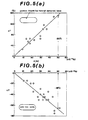
- FIG. 4 shows the relation of the rate of gaseous oxygen feed, the amount of silicon removed in preference of manganese ( ⁇ [%Si]/ ⁇ [ %Mn ]) and the amount of carbon removed.
- FIG. 5(a) shows the relation between the rate of gaseous oxygen feed and the temperatures before and after the desiliconization
- FIG. 5(b) shows the relation between the rate of solid iron oxide feed and the temperatures before and after the desiliconization.
- the three figure:; are based on the data obtained by deailieoniz- ing 60 tons of molten iron which contained 0.52 to 0.600 of silicon, 0.48 to 0.5% of manganese and 4.45 to 4.57 carbon and which had a temperature of 1750 co 1360°C.
- the silicon content was reduced to 0.40 to 0.50.%.
- Gaseous oxygen was injected into the molten iron through a lance comprising a 13 Cr stainless steel nozzle (ID: 6-15 mm) clad with a castable refractory. The lance was immersed in the molten metal to a depth of 500 to 1000 mm. As shown in FIG. 4, if gaseous oxygen is injected into the molten iron directly, the amount of carbon removed is increased in proportion to the oxygen supply rate, but the increase is by only about 0.05 to 0.15% which is almost the same as the increase resulting from the use of solid iron oxides.
- the removal of manganese is inhibited as the gaseous oxygen feed rate is increased, and if the rate is 0.03 Nm 3 /min/t ⁇ p. or more, the ratio of the removed silicon to manganese ( ⁇ [%Si]/ ⁇ [%Mn]) is at least 1.5 which is the same as the value obtained by using solid iron oxides. Therefore, gaseous oxygen must be supplied at a rate of 0.03 Nm 3 /min/t.p. or more to achieve the desired preferential desiliconization.
- the removal of manganese is inhibited as the rate of gaseous oxygen feed is increased probably because the manganese monoxide (MnO) once formed by oxygen injecting is reduced by Si in the high-temperature range in the reaction zone of oxygen injection. The more oxygen injected into the molten iron. the higher the temperature of the reaction zone and the more accelerated the reduction of MnO, wi.th the result that the removal of manganese is inhibited.
- FIG. 6 shows, even if gaseous oxygen is fed at a constant rate, the oxygen utility in preferential desiliconization (the ratio of oxygen spent for oxidation of silicon to the total oxygen supplied) is decreased if the the molten iron to be desiliconized has low silicon content.
- the study of the present inventors has revealed that if the oxygen utility in desiliconization is less than 40%, rapid decarburization occurs and the resulting boiling of the molten iron makes the subsequent treatment in a mixer ladle car or ladle difficult.
- FIG. 6 shows the relation between the silicon content (%) of molten iron and the oxygen utility in preferential desiliconization according to the present invention.
- the figure is based on the data obtained by desiliconizing 60 tons of molten iron with a silicon content of 0.20 to 1.10% by blowing 0.16 Nm 3 of gaseous oxygen per minute per ton of the pig through a lance immersed in the molten iron to a depth of 700 to 1000 mm.
- the lance had a sheathed nozzle, and gaseoues oxygen was fed through the inner tube and nitrogen gas for cooling (or protecting) the nozzle was fed through the space between the inner and outer tubes at a rate of 0:03 to 0.05 Nm 3 /min/t ⁇ p.
- the silicon content was reduced to 0.07 to 0.12%.
- the present iaventors noted the effectiveness of adjusting the rate of gaseous oxygen feed to a proper range. If gaseous oxygen is injected into the molten iron, the temperature of the melt is increased locally, and decarburization occurs in the low Si range more easily than when solid iron oxides are used or gaseous oxygen is blown onto the molten iron. This can be prevented and only silicon can be oxidized by reducing the rate of gaseous oxygen feed as the silicon content is decreased. At a melt temperate of 1600°C or lower, oxygen has greater affinity for silicon than for carbon, and with insufficient oxygen supply, Si can be oxidized in preference to carbon.
- FIG. 7 shows that three clearly different co-relations between the gaseous oxygen supply rate (Vo 2 ) and the oxygen utility for preferential desiliconization (a S i) are obtained depending upon the Si content of the molten iron.
- FIG. 7 also shows that to maintain at least 40% of dg i , V 02 must be controlled to satisfy the following relations:
- the rate of gaseous oxygen feed (Vo 2 ) is controlled depending upon the Si content of the molten iron to satisfy the formulae (II) and (III): and
- the uppwer limit of the gaseous oxygen supply rate is defined by the formula (I).
- the formula (II) is satisfied, the boiling. of the molten iron can be completely prevented and a consistent operation can be achieved in spite of the fluctuating process parameters that will accompany commercial operations.
- the formula (III) defining the lower limit is also dictated by the experience of the present inventors.
- gaseous oxygen feed rate is too low, a longer time is required to perform desiliconization and the temperature of the molten iron drops during the treatment, and heat loss occurs contrary to the objects of the present invention. This is conspicuous when the molten iron being desiliconized has high Si content. The extended duration of desiliconization is also incompatible with high productivity.
- Vo 2 is reduced in increments or continuously, and this is effective for shortening the duration of desiliconization and maintaining high oxygen utility.
- the oxygen supply rate (Vo 2 ) is desirably adjusted to an optimum range depending upon the Si content of the molten iron, so it is most preferred to monitor the decreasing the Si content of the molten iron being desiliconized and inject an optimum amount of gaseous oxygen. To meat this requirement, a sample is taken from the molten iron at intervals and its Si content is checked to see if the gaseous oxygen is being supplied at the proper Vo 2 , and if not, a correction is made to obtain the proper value.
- the Vo 2 is preset to a certain level depending upon the Si content before treatment, the subsequent change in the Si content can be estimated beforehand, and therefore, it is possible to porform desiliconization by supplying gaseous oxygen at a continuously decreusing rate.
- the gaseous oxygen may be supplied at a rotn that is decreased in increments at given intorvais. specific conditions of commercial operations.
- the temperature of the molten iron being desiliconzied by injecting gaseous oxygen is increased in proportion to the amount of silicon removed, and unlike solid oxygen (FIG. 5(b)), gaseous oxygen does not reduce the temperature of the molten iron being desiliconized. But as more silicon is removed, the temperature of the molten iron is increased too much, and inhibition of decarburization, another object of the present invention, becomes difficult. Furthermore, if the temperature of the molten iron becomes excessively high, the refactory on the vessel and lance may be eroded, so a coolant is preferably added to the molten iron to prevent it from becoming excessively hot.
- Preferred coolants are scrap, limestone, iron ores, mill scale, sintered ores, pellets and iron sand.
- solid iron oxides such as iron ores, mill scale, sintered ores, pellets and iron sand are particularly preferred.
- gaseious oxygen may be blown into the molten iron through an immersed lance. If the lance is immersed less.than 200 mm deep from the surface of the bath, the refining effect of the injected oxygen is not enough to inhibit the CO reaction and the desired preferential desiliconization may not be achieved. What is more, slopping of the molten iron will occur to increase the iron loss. Therefore, the lance is desirably immersed to a depth of at least 200 mm. A con- .sumable lance is advantageous because this is less cosai; and easy to handle. The consumable lance should nor: have adverse effeets on the composition of the molten iron i:
- the lance may be made of an oxygen conduit that is clad.with a castable refractory, and this type has particularly great resistance to high temperatures. Any composition of castable refractory can be used, but Al 2 O 3 refractories are especially suitable.
- the oxygen conduit is desirably made of Cr stainless steels having great resistance to oxidation at high temperatures.
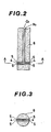
- FIGS. 1-10 A typical example of the lance construction is illustrated in FIGS.
- the gaseous oxygen is fed through an inner tube 4, and.
- a protective coolant such as a gaseous material (e.g. N 2 , C0 2 , Ar, CH 4 and C 3 H e ), or a liquid material(e.g. kerosine) is fed through the space between the inner tube and an outer tube 5.
- a gaseous material e.g. N 2 , C0 2 , Ar, CH 4 and C 3 H e
- a liquid material(e.g. kerosine) is fed through the space between the inner tube and an outer tube 5.
- the castable refractory is indicated by the numeral 6.
- the lance preferably has a sheathed nozzle so that a coolant can be fed simultaneously with oxygen to prevent erosion of the nozzle, but a single-walled nozzle may also be used.
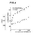
- a nozzle with a "straight" ' opening is generally preferred since it is easy to fabricate and serves all purposes, but to minamlre the nossle erosion due to the ascending of the injected oxygen, a nozzle of "inverted T shape" with openings in diametric posiions may be used.
- the lance may have any shape and dimensions so long as gaseous oxygen can be blown in the molten iron taroun it.
- the foregoing description a ames the only use of an immersed lance as means through which to inject gaseous oxygen into the molten iron, but the advantages of the prevent invention can be achieved by using a tuyere positioned in the bottom or the side wall in the lower part of the vessel, provided that the requirements mentioned above are met..
- FIG. 1 One embodiment of the present invention is illustrated in FIG. 1 wherein gaseous oxygen is supplied to the molten iron through an immersed lance 4 and an agitating gas through a tuyere 3 provided in the bottom of a la
- the gas used as a protective coolant to protect the nozzle is generally fed in an amount of 5 to 30 vol% of the gaseous oxygen.
- the gaseous oxygen and coolant gas are fed to the molten.iron through a sheathed pipe separately or through a'single-walled pipe in admixture.
- the coolant gas. and gaseous oxygen supplied provide the molten iron with the energy for agitating it.
- the agitating energy is largely determined by the rate of the gas feed.
- the rate of gaseous oxygen feed (V 02 ) is determined as described hereinabove, and the coolant gas is fed in an amount of 5 to 30% of the so determined oxygen feed rate.
- the molten iron with low Si content is given insufficient agitating energy.
- the molten iron with low Si content is preferably supplied with more coolant gas per gaseous oxygen- than the iron with high Si content.
- To provide more agitating energy for the molten iron with low Si content is important for letting the blown oxygen diffuse into the molten iron quickly, increasing the change of reastion bei in silicon and oxygen and accolerating the desired preferential desiliconization.
- the oxygen utility in preferential desiliconization can be increased further by supplementing the agitating energy of the gases with that of a mechanical means such as an impeller.
- the rate of gaseous oxygen feed (V 02 ) can be increased for achieving a predetermined oxygen utility in preferential desiliconization.
- the energy for agitating the molten iron may also be provided by supplying a neutral or inert gas (e.g. N 2 , COi or Ar) from below through a porous refractory embedded in the bottom or the lower part of the side wall of the vessel. This method is effective for accelerating the desired desiliconization.
- the present invention is capable of desiliconizing molten iron efficiently by using gaseous oxygen.
- molten iron in a ladle or other melt conveyors can be desiliconized with gaseous oxygen without causing boiling or other unwated effects.
- the oxygen utility in preferential desiliconization can be held at 40% or more.
- the invention can achieve better heat control and selection of input charges in the overall steelmaking process. -For these reasons, the present invention will prove very useful to the steelmaking industry.
- the present invetion is particularly effective for desiliconizing molten iron wich high Si content.
- the silicon content of the molten iron must be 0.20% or less after the desiliconization.
- the higher the Si content of tne molten iron before desiliconization the more the silicon that is removed, but if solid iron oxides such as mill scale are used as a desiliconizing agent, the temperature of the molten iron drops very rapidly to cause insufficiency in the heat source necessary for the subsequent steps.
- the technical advantages of the present invention are particularly great if it is used to desiliconize molten iron with high Si content.
- the present invention achieves efficient preferential desiliconization of molten iron.
- the present invention also eliminates the defects of the conventional method of desiliconizing molten iron by feeding solid iron oxides or gaseous oxygen.
- the present invention accomplishes more efficient desiliconization of molten iron and achieves better heat control and selection of input charges in the overall steelmaking process.
- the invention will prove very useful to the steelmaking industry.
Landscapes
- Chemical & Material Sciences (AREA)
- Engineering & Computer Science (AREA)
- Materials Engineering (AREA)
- Metallurgy (AREA)
- Organic Chemistry (AREA)
- Manufacturing & Machinery (AREA)
- Refinement Of Pig-Iron, Manufacture Of Cast Iron, And Steel Manufacture Other Than In Revolving Furnaces (AREA)
Applications Claiming Priority (2)
| Application Number | Priority Date | Filing Date | Title |
|---|---|---|---|
| JP56129609A JPS5831012A (ja) | 1981-08-19 | 1981-08-19 | 気体酸素吹込みによる溶銑の優先脱Si方法 |
| JP129609/81 | 1981-08-19 |
Publications (2)
| Publication Number | Publication Date |
|---|---|
| EP0073274A1 true EP0073274A1 (de) | 1983-03-09 |
| EP0073274B1 EP0073274B1 (de) | 1987-04-01 |
Family
ID=15013686
Family Applications (1)
| Application Number | Title | Priority Date | Filing Date |
|---|---|---|---|
| EP81110086A Expired EP0073274B1 (de) | 1981-08-19 | 1981-12-02 | Verfahren zum Vorentsilizieren von Eisenschmelzen durch Einblasen von gasförmigen Sauerstoff |
Country Status (4)
| Country | Link |
|---|---|
| US (1) | US4394165A (de) |
| EP (1) | EP0073274B1 (de) |
| JP (1) | JPS5831012A (de) |
| DE (1) | DE3176064D1 (de) |
Families Citing this family (5)
| Publication number | Priority date | Publication date | Assignee | Title |
|---|---|---|---|---|
| JPH03107410A (ja) * | 1989-09-22 | 1991-05-07 | Nippon Steel Corp | 溶銑の脱珪方法 |
| US5443572A (en) * | 1993-12-03 | 1995-08-22 | Molten Metal Technology, Inc. | Apparatus and method for submerged injection of a feed composition into a molten metal bath |
| HRP970303B1 (en) * | 1996-06-05 | 2002-06-30 | Holderbank Financ Glarus | Method for making pozzolans, synthetic blast-furnance slag, belite or alite clinkers, and pig-iron alloys, from oxidic slag and a device for implementing this method |
| CN104419798B (zh) * | 2013-09-05 | 2017-02-22 | 鞍钢股份有限公司 | 一种利用cas‑ob精炼炉铁水预脱硅的方法 |
| JP6110018B2 (ja) * | 2014-12-12 | 2017-04-05 | 株式会社木下製作所 | 鋳鉄のマンガン除去方法 |
Citations (4)
| Publication number | Priority date | Publication date | Assignee | Title |
|---|---|---|---|---|
| GB718001A (en) * | 1951-09-08 | 1954-11-03 | Huettenwerk Haspe Ag | Improvements in or relating to processes for the pre-treatment of raw thomas iron |
| AT185831B (de) * | 1951-06-15 | 1956-06-11 | Westfalenhuette Ag | Verfahren zur Vorfrischen von Roheisen oder Stahleisen in der Pfanne |
| DE2942779A1 (de) * | 1978-10-24 | 1980-05-08 | Nippon Steel Corp | Verfahren zur herstellung von stahl |
| GB2072221A (en) * | 1980-03-21 | 1981-09-30 | Nippon Steel Corp | Steelmaking process with separate refining steps |
Family Cites Families (4)
| Publication number | Priority date | Publication date | Assignee | Title |
|---|---|---|---|---|
| US2793110A (en) * | 1953-11-13 | 1957-05-21 | Kosmider Johannes | Process for manufacturing a high grade steel |
| JPS5378913A (en) * | 1976-12-24 | 1978-07-12 | Nippon Steel Corp | Refining method for steel for decreasing generating amount of slag |
| JPS54158321A (en) * | 1978-06-03 | 1979-12-14 | Nippon Steel Corp | Preferentially desiliconizing method for hot iron |
| JPS56133413A (en) * | 1980-03-21 | 1981-10-19 | Nippon Steel Corp | Steel making method by divided refining |
-
1981
- 1981-08-19 JP JP56129609A patent/JPS5831012A/ja active Pending
- 1981-11-30 US US06/325,999 patent/US4394165A/en not_active Expired - Lifetime
- 1981-12-02 EP EP81110086A patent/EP0073274B1/de not_active Expired
- 1981-12-02 DE DE8181110086T patent/DE3176064D1/de not_active Expired
Patent Citations (4)
| Publication number | Priority date | Publication date | Assignee | Title |
|---|---|---|---|---|
| AT185831B (de) * | 1951-06-15 | 1956-06-11 | Westfalenhuette Ag | Verfahren zur Vorfrischen von Roheisen oder Stahleisen in der Pfanne |
| GB718001A (en) * | 1951-09-08 | 1954-11-03 | Huettenwerk Haspe Ag | Improvements in or relating to processes for the pre-treatment of raw thomas iron |
| DE2942779A1 (de) * | 1978-10-24 | 1980-05-08 | Nippon Steel Corp | Verfahren zur herstellung von stahl |
| GB2072221A (en) * | 1980-03-21 | 1981-09-30 | Nippon Steel Corp | Steelmaking process with separate refining steps |
Non-Patent Citations (5)
| Title |
|---|
| Patent Abstracts of Japan, Vol. 2, No. 117, 29 September 1978, page 2195C78; & JP-A-53 078 913 * |
| Patent Abstracts of Japan, Vol. 4, No. 19, 16 Februar 1980, page 155C73; & JP-A-54 158 321 * |
| Patent Abstracts of Japan, Vol. 5, No. 120, 4 August 1978, & JP-A-56 055 511 * |
| Patent Abstracts of Japan, Vol. 6, No. 57, 14 April 1982, & JP-A-56 169 716 * |
| STAHL UND EISEN, Vol. 76, No. 23, November 1956, Dusseldorf, J. SITTARD: "Die Vorfrischanlage der Eisenwerk-Gesellschaft Maximilianshütte A.G." pages 1554 to 1561 * |
Also Published As
| Publication number | Publication date |
|---|---|
| DE3176064D1 (en) | 1987-05-07 |
| US4394165A (en) | 1983-07-19 |
| JPS5831012A (ja) | 1983-02-23 |
| EP0073274B1 (de) | 1987-04-01 |
Similar Documents
| Publication | Publication Date | Title |
|---|---|---|
| US4586956A (en) | Method and agents for producing clean steel | |
| US4295882A (en) | Steel making process | |
| US4410360A (en) | Process for producing high chromium steel | |
| US3323907A (en) | Production of chromium steels | |
| JP6806288B2 (ja) | 鋼の製造方法 | |
| GB2093864A (en) | Process for refining high-chronium steels by oxygen-blowing | |
| JP4736466B2 (ja) | 高クロム溶鋼の溶製方法 | |
| US4394165A (en) | Method of preliminary desiliconization of molten iron by injecting gaseous oxygen | |
| US4001012A (en) | Method of producing stainless steel | |
| EP0033780B2 (de) | Verfahren zur Auswurfverminderung beim Frischen im bodenblasenden Konverter | |
| RU2118376C1 (ru) | Способ производства ванадиевого шлака и природнолегированной ванадием стали | |
| US4891064A (en) | Method of melting cold material including iron | |
| RU2201968C2 (ru) | Способ передела ванадиевого чугуна | |
| KR900002710B1 (ko) | 급속탈탄 제강공정 | |
| JP4894325B2 (ja) | 溶銑の脱燐処理方法 | |
| JP7852660B2 (ja) | 溶銑の予備処理方法 | |
| JPS6379910A (ja) | 出鋼流へのスラグ混流防止法 | |
| CA1051204A (en) | Method of controlling temperature in q-bop | |
| SU1744122A1 (ru) | Способ выплавки и внепечной обработки стали | |
| KR100225249B1 (ko) | 슬로핑 발생 억제를 위한 잔류 슬래그량 조절방법 | |
| JP2842185B2 (ja) | 溶融還元によるステンレス溶湯の製造方法 | |
| SU1337417A1 (ru) | Способ выплавки стали в конвертере | |
| US5156671A (en) | Method for dephosphorization of chromium-containing molten pig iron with reduced oxidation loss of chromium | |
| US4066442A (en) | Method of making chrome steel in an electric arc furnace | |
| SU1604165A3 (ru) | Способ производства стали в конвертере |
Legal Events
| Date | Code | Title | Description |
|---|---|---|---|
| PUAI | Public reference made under article 153(3) epc to a published international application that has entered the european phase |
Free format text: ORIGINAL CODE: 0009012 |
|
| AK | Designated contracting states |
Designated state(s): BE DE FR GB IT |
|
| 17P | Request for examination filed |
Effective date: 19830414 |
|
| ITF | It: translation for a ep patent filed | ||
| GRAA | (expected) grant |
Free format text: ORIGINAL CODE: 0009210 |
|
| AK | Designated contracting states |
Kind code of ref document: B1 Designated state(s): BE DE FR GB IT |
|
| ET | Fr: translation filed | ||
| REF | Corresponds to: |
Ref document number: 3176064 Country of ref document: DE Date of ref document: 19870507 |
|
| PLBE | No opposition filed within time limit |
Free format text: ORIGINAL CODE: 0009261 |
|
| STAA | Information on the status of an ep patent application or granted ep patent |
Free format text: STATUS: NO OPPOSITION FILED WITHIN TIME LIMIT |
|
| 26N | No opposition filed | ||
| PG25 | Lapsed in a contracting state [announced via postgrant information from national office to epo] |
Ref country code: DE Effective date: 19900901 |
|
| ITTA | It: last paid annual fee | ||
| PGFP | Annual fee paid to national office [announced via postgrant information from national office to epo] |
Ref country code: GB Payment date: 19961125 Year of fee payment: 16 |
|
| PGFP | Annual fee paid to national office [announced via postgrant information from national office to epo] |
Ref country code: FR Payment date: 19961211 Year of fee payment: 16 |
|
| PGFP | Annual fee paid to national office [announced via postgrant information from national office to epo] |
Ref country code: BE Payment date: 19970214 Year of fee payment: 16 |
|
| PG25 | Lapsed in a contracting state [announced via postgrant information from national office to epo] |
Ref country code: GB Free format text: LAPSE BECAUSE OF NON-PAYMENT OF DUE FEES Effective date: 19971202 |
|
| PG25 | Lapsed in a contracting state [announced via postgrant information from national office to epo] |
Ref country code: FR Free format text: THE PATENT HAS BEEN ANNULLED BY A DECISION OF A NATIONAL AUTHORITY Effective date: 19971231 Ref country code: BE Free format text: LAPSE BECAUSE OF NON-PAYMENT OF DUE FEES Effective date: 19971231 |
|
| BERE | Be: lapsed |
Owner name: NIPPON STEEL CORP. Effective date: 19971231 |
|
| GBPC | Gb: european patent ceased through non-payment of renewal fee |
Effective date: 19971202 |
|
| REG | Reference to a national code |
Ref country code: FR Ref legal event code: ST |