EP0073358A2 - Vorrichtung zum Tragen von Segeln - Google Patents
Vorrichtung zum Tragen von Segeln Download PDFInfo
- Publication number
- EP0073358A2 EP0073358A2 EP82107054A EP82107054A EP0073358A2 EP 0073358 A2 EP0073358 A2 EP 0073358A2 EP 82107054 A EP82107054 A EP 82107054A EP 82107054 A EP82107054 A EP 82107054A EP 0073358 A2 EP0073358 A2 EP 0073358A2
- Authority
- EP
- European Patent Office
- Prior art keywords
- boom
- mast
- sail
- clew
- tension
- Prior art date
- Legal status (The legal status is an assumption and is not a legal conclusion. Google has not performed a legal analysis and makes no representation as to the accuracy of the status listed.)
- Withdrawn
Links
Images


Classifications
-
- B—PERFORMING OPERATIONS; TRANSPORTING
- B63—SHIPS OR OTHER WATERBORNE VESSELS; RELATED EQUIPMENT
- B63H—MARINE PROPULSION OR STEERING
- B63H9/00—Marine propulsion provided directly by wind power
- B63H9/04—Marine propulsion provided directly by wind power using sails or like wind-catching surfaces
- B63H9/06—Types of sail; Constructional features of sails; Arrangements thereof on vessels
-
- B—PERFORMING OPERATIONS; TRANSPORTING
- B63—SHIPS OR OTHER WATERBORNE VESSELS; RELATED EQUIPMENT
- B63H—MARINE PROPULSION OR STEERING
- B63H9/00—Marine propulsion provided directly by wind power
- B63H9/04—Marine propulsion provided directly by wind power using sails or like wind-catching surfaces
- B63H9/08—Connections of sails to masts, spars, or the like
- B63H9/10—Running rigging, e.g. reefing equipment
- B63H9/1021—Reefing
- B63H9/1035—Reefing by furling around or inside the mast
Definitions
- This invention provides a sail support and control system designed for use as a propulsion assist system on a cargo vessel.
- An unstayed mast is mounted on a ship so as to be rotatable in relation thereto, and is provided with a cantilever boom.
- a motor and suitable winches are provided on the boom which take in and pay out sheets which extend from the end of the boom around suitably positioned fairleads to dead ends on the deck, to enable the boom to be swung to a desired position in relation to the ship, and to provide sheet tension to hold the boom in the desired lateral position.
- the cantilever mounting of the boom eliminates any requirement that the sheets provide downward tension against clew puli.
- a second motor is provided on the boom support and is geared to. the mast so that operation of the motor causes rotation of the mast. When the motor is not operating, the boom and mast are locked in fixed relation to each other by said gearing.
- Swinging of the boom to a new angular position in relation to the ship therefore causes the mast to rotate a like amount so that a change in position of the boom does not change the amount of sail exposed.
- the outhaul tension line is payed out and taken in from a drum on the mast which is two times the mast diameter.
- the other end of the outhaul tension line is connected to the clew of the sail by a two part block, and then dead ended to a hydraulic cylinder or winch, so that a continuous tension may be applied to the line during sail reefing or unfurling.
- the downhaul tension is provided by a line connected to the clew through a two part block disposed between the clew and a trolley on the boom, said trolley riding in and out along the boom as the clew moves in and out during reefing or letting out the sail.
- Means is provided for maintaining a desired tension on the downhaul line when the trolley is stationary, and for reducing the tension to a lesser amount when the trolley moves in response to clew movement.
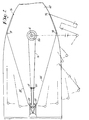
- a support and control system for a sail 10 which comprises a mast support 12, a mast 14 which is rotatably mounted on the support, and a cantilever boom 16 which is mounted on the mast support so as to be laterally rotatable about the mast axis through about 180 degrees.
- the boom is swung to a desired position by port and starboard hydraulic winches 18 and 20 which pay out and take in port and starboard sheets 22 and 24.
- the mast is rotated in relation to the boom, to furl and unfurl the sail, and to position the luff of the sail for maximum aerodynamic efficiency by a hydraulic motor 26 which is mounted on a boom support cylinder 28, driving a gear 30 which meshes with a gear 32 on the mast.
- Tension to the clew of the sail is applied through an outhaul line 34 and a downhaul line 36 in a manner to be described.
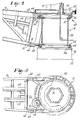
- the mast support assembly 12 which comprises a foot portion 38 secured to the deck 40 of the ship.
- a first slewing ring bearing 42 is mounted on the foot portion 38, with the outer race 44 thereof attached to the foot portion 38, and the inner race 46 being fastened to the boom support cylinder 28.
- a second slewing ring bearing 48 is mounted on the boom support cylinder 28 with the inner race 50 thereof attached to the top of the boom support cylinder.
- the outer race 52 thereof carries an external gear 32 for a purpose to appear hereinafter.
- the boom support cylinder 28 carries upper and lower boom support brackets 60 and 62 which have apertures 64 and 66 respectively to allow boom support arms 68 and 70 to be removably mounted thereon by pins 72 and 74.
- the above described structure allows the boom support cylinder and boom to be rotatable in relation to the deck of the ship, through lower slewing ring 42, and allows the mast to be rotatable in relation to the boom through upper slewing ring 48.
- the boom is maintained in a desired angular relation to the ship by the sheet winches 18 and 20 in a manner to be described hereinafter, and the mast is rotated in a desired direction to furl or unfurl the sail by the mast rotating motor 26 and gear 30 driving the gear 32 on the outer race of the upper slewing ring. Since the boom is normally maintained in a fixed position, depending on the relative wind, operation of the motor 26 will cause rotation of the mast, to reef or let out the sail in a manner to appear hereinafter.
- the boom and mast are locked together by the gears 30 and 32 so that if the boom 16 is swung to a different position, the mast rotates through the same angle as the boom, so that the amount of sail exposed does not change.
- the mast can also be rotated when the sail is fully unfurled, in either direction as necessary, to position the luff of the sail in the proper orientation in relation to the mast for the best aerodynamic efficiency, as will be described hereinafter.
- the position of the boom is controlled by the separate port and starboard sheet.winches 18 and 20 which take in and pay out sheets 22 and 24 under controlled tension so that the position of the boom can be fixed.
- Each sheet is attached to a dead end 76 on the deck 40 forward of the mast (see Fig.2) from where it passes around a fairlead post 78 on the deck approximately abeam of the mast.
- a pair of flag blocks 80 and 82 on the end of the boom lead the sheets to fixed sheaves 84 and 86, which lead the sheets to the sheet winches 18 and 20 on the boom.
- a pair of fairlead posts 88 and 90 are provided at the fore and aft position of the boom, so positioned that when the boom is swung out to starboard, for example, the port sheet passes outside of port fairlead 78 and behind the posts 88 and 90, so that the angle of the sheet to the boom is more favorable than if the sheet came directly from the port fairlead post 78.
- the centerline fairlead posts may be mounted on the surface of a cargo crane support, however in other installations, they may be mounted on a platform of suitable height.
- the sheet winches 18 and 20 are operated independently so that one winch pays out one sheet and the other winch takes in the other sheet, with both sheets being under controlled tension.
- the winch drums are locked against rotation, with tension on both sheets, so that the boom is prevented from swinging in either direction.
- the sail is furled and unfurled by rotation of the mast by motor 26.
- the outhaul line 34 is secured to the furling drum 58 on the mast, and extends along the boom to the outer end thereof to a block system 92 attached to the clew, and then to a tension winch 98 mounted on the boom.
- the outhaul drum 58 preferably has a diamter twice that of the mast. As illustrated in Fig.6, rotation of the mast in a clockwise direction (as seen from above) by the motor 26 causes the sail to wrap onto the mast on the port side thereof, and causes the line 34 to unwind from the starboard side of the drum 58 at a rate twice the rate at which the sail winds onto the mast.
- the clew pulley 94 of the two part block moves at the same rate as that at which the sail winds around the mast.
- the end of the outhaul line extends from the block system 92 to an outhaul tension winch 96.
- An important feature of the outhaul system is the fact that the tension winch 96 maintains a continuous tension on the outhaul line and hence on the clew of the sail, however, no substantial amount of line is taken in or payed out by the tension winch. Therefore, the mast rotating motor need only overcome the friction of the moving components, and can be of lower horsepower than if it were required to pull the sail and apply the necessary tension thereto.
- the clew does not follow a path paralled to the boom but follows an arcuate path (see Fig. , 3 ) due to the taper of the mast, therefore, as the clew moves from the end of the boom toward the mast, extra line is required in the system between the outhaul drum 58 and the clew pulley 94, which is provided from the outhaul tension winch 98.
- the winch 96 also adjusts the length of the outhaul line to compensate for sail stretching. In some cases, if the amount of the extra line required is not too great, a hydraulic cylinder could be used in place of the winch 96.
- Downhaul tension is applied to the clew of the sail through a block system 98, comprising a single upper block 100 and a double lower block 102.
- the upper block-100 is secured to the clew of the sail, and the lower double block is secured to a trolley 104 which has rollers 106 riding under a track 108 on the boom 16.
- the downhaul line 36 is dead ended at the outer end of the boom, passes around the block system 98, up the boom to a fixed sheave 110, and then to a block system 112 which comprises a fixed double block 114 and a movable double block 116 and is dead ended, at the fixed double block 114, providing a 4 part line system with a mechanical advantage of 4.
- the movable double block 116 is fastened to the piston of a hydraulic cylinder 118, which provides tension to the downhaul system. With tension on the line 36, the upper and lower blocks 100 and 102 draw together, applying tension to the clew of the sail.
- the tension on the line 36 may be slightly reduced. This allows the trolley 104 to more easily travel inwardly when the clew of the sail moves inwardly on energizing the motor 26.
- the clew pulls the block system 98 inwardly along the boom, with the trolley rolling along the track 108.
- the mast rotating motor is stopped, and the tension in line 36 may then be increased to the amount necessary to maintain the clew the desired position in relation to the boom.
- the above described system allows adequate tension to be maintained in the clew even during takingin and letting out sail.
- the boom when the sail is completely unfurled, the boom may be rotated in either direction to position the luff of the sai.l in the best orientation for maximum aerodynamic efficiency, as illustrated in Fig. 11 and 12.
- the boom when the apparent wind is 30 degrees off the port bow, the boom extends substantially fore and aft. If the orientation of the mast is such that the sail extends from the centerline of the mast (see Fig.11) the airflow around the mast causes turbulence on the forward portion of the lee side of the sail, preventing the establishment of the full pressure differential between the lee and weather sides of the sail.
- a pair of winches is provided on the boom, which handle separate port and starboard sheets, in some cases a single winch may be used with,a single sheet which is continuous between the port and starboard dead ends.
- the invention includes a sail support system as set out in claim 1 in which means is provided for maintaining a pre-determined continuous tension in said sheets during lateral movement of the boom.
- the invention includes a system as set out in claim 3 in which fairleads-are provided at the outer end of the boom substantially on the centerline thereof, and said tension line passes around said fairleads on the after side thereof.
- the invention includes a system as set out in claim 3 in which said winch means comprises a pair of winches, one winch taking in and paying out the tension line on the port side of the boom, the other winch taking in and paying out the tension line on the starboard side of the boom.
- the invention includes an assembly as set out in claim 4 in which the outer member of the upper bearing carries an external gear, and the boom support carries a motor driving a gear which is meshed with the external gear.
- the invention includes an assembly as set out in claim 4 in which said boom support carries upper and lower boom support arms to allow assembly of the boom thereon.
- the invention includes a system as set out in claim 7 in which said.downhaul line is dead ended at the ounter end of the boom, passes around a first sheave attached to the trolley, around a second sheave attached to the clew of the sail around a third sheave attached to the trolley and up the boom to means for maintaining tension on said line.
Landscapes
- Engineering & Computer Science (AREA)
- Mechanical Engineering (AREA)
- Sustainable Development (AREA)
- Sustainable Energy (AREA)
- Chemical & Material Sciences (AREA)
- Combustion & Propulsion (AREA)
- Life Sciences & Earth Sciences (AREA)
- Ocean & Marine Engineering (AREA)
- Jib Cranes (AREA)
- Load-Engaging Elements For Cranes (AREA)
- Epoxy Resins (AREA)
- Adhesives Or Adhesive Processes (AREA)
- Golf Clubs (AREA)
- Control And Safety Of Cranes (AREA)
- Toys (AREA)
Applications Claiming Priority (2)
| Application Number | Priority Date | Filing Date | Title |
|---|---|---|---|
| US290234 | 1981-08-05 | ||
| US06/290,234 US4499841A (en) | 1981-08-05 | 1981-08-05 | Sail rigging and control system |
Publications (2)
| Publication Number | Publication Date |
|---|---|
| EP0073358A2 true EP0073358A2 (de) | 1983-03-09 |
| EP0073358A3 EP0073358A3 (de) | 1984-01-04 |
Family
ID=23115087
Family Applications (1)
| Application Number | Title | Priority Date | Filing Date |
|---|---|---|---|
| EP82107054A Withdrawn EP0073358A3 (de) | 1981-08-05 | 1982-08-04 | Vorrichtung zum Tragen von Segeln |
Country Status (7)
| Country | Link |
|---|---|
| US (1) | US4499841A (de) |
| EP (1) | EP0073358A3 (de) |
| JP (1) | JPS5847699A (de) |
| AU (1) | AU8661182A (de) |
| BR (1) | BR8204591A (de) |
| FI (1) | FI822728L (de) |
| NO (1) | NO822672L (de) |
Cited By (1)
| Publication number | Priority date | Publication date | Assignee | Title |
|---|---|---|---|---|
| EP0096329A3 (de) * | 1982-06-03 | 1985-05-15 | Wind Ship Development Corporation | Einrichtung zum Tragen und Kontrollieren von Segeln |
Families Citing this family (7)
| Publication number | Priority date | Publication date | Assignee | Title |
|---|---|---|---|---|
| AU585930B2 (en) * | 1985-01-14 | 1989-06-29 | Patrick Murray Johnston | Rigging for a wind propelled craft |
| EP0245263A1 (de) * | 1985-01-14 | 1987-11-19 | JOHNSTON, Gregory Owen | Takelage für windgetriebenes fahrzeug |
| JPS621691A (ja) * | 1985-06-26 | 1987-01-07 | Yokoyama Zosen Sekkei Jimusho:Kk | 船舶の自動操縦方法および装置 |
| SE9401898L (sv) * | 1994-06-02 | 1995-05-15 | Selden Mast Ab | Anordning vid bom för segelfarkost |
| DE19721024A1 (de) * | 1997-05-20 | 1998-11-26 | Hanjo Dr Kreitz | Selbststeuernde Segelschiffe |
| KR101524763B1 (ko) * | 2013-10-04 | 2015-06-11 | 주식회사 호룡 | 고가 사다리차 |
| US20180127075A1 (en) | 2016-10-15 | 2018-05-10 | Alistair JOHNSON | Tig rig sail system |
Family Cites Families (8)
| Publication number | Priority date | Publication date | Assignee | Title |
|---|---|---|---|---|
| US3149603A (en) * | 1963-03-11 | 1964-09-22 | Joseph D Sainte-Claire | Sailing ship rigging and its operation |
| US3260230A (en) * | 1964-10-12 | 1966-07-12 | Kauert Walter | Sail controlling means |
| US3332384A (en) * | 1965-10-21 | 1967-07-25 | John T Potter | Sailboat |
| US4074647A (en) * | 1976-07-08 | 1978-02-21 | Delaney Richard D | Sailing rig having camber adjustments |
| US4061101A (en) * | 1977-02-23 | 1977-12-06 | Gregory Edward Cook | Sail furling apparatus |
| NL7901568A (nl) * | 1979-02-27 | 1980-08-29 | Robbert Das | Zeilschip. |
| US4367688A (en) * | 1980-12-12 | 1983-01-11 | Godfrey Thomas B A | Sailboat rig |
| US4407419A (en) * | 1981-12-30 | 1983-10-04 | Clements Shannon K | Portable boom support for vehicles |
-
1981
- 1981-08-05 US US06/290,234 patent/US4499841A/en not_active Expired - Fee Related
-
1982
- 1982-07-30 AU AU86611/82A patent/AU8661182A/en not_active Abandoned
- 1982-08-04 BR BR8204591A patent/BR8204591A/pt unknown
- 1982-08-04 NO NO822672A patent/NO822672L/no unknown
- 1982-08-04 EP EP82107054A patent/EP0073358A3/de not_active Withdrawn
- 1982-08-05 JP JP57136801A patent/JPS5847699A/ja active Pending
- 1982-08-05 FI FI822728A patent/FI822728L/fi not_active Application Discontinuation
Cited By (1)
| Publication number | Priority date | Publication date | Assignee | Title |
|---|---|---|---|---|
| EP0096329A3 (de) * | 1982-06-03 | 1985-05-15 | Wind Ship Development Corporation | Einrichtung zum Tragen und Kontrollieren von Segeln |
Also Published As
| Publication number | Publication date |
|---|---|
| BR8204591A (pt) | 1983-07-26 |
| FI822728A7 (fi) | 1983-02-06 |
| NO822672L (no) | 1983-02-07 |
| JPS5847699A (ja) | 1983-03-19 |
| AU8661182A (en) | 1983-02-10 |
| EP0073358A3 (de) | 1984-01-04 |
| FI822728A0 (fi) | 1982-08-05 |
| FI822728L (fi) | 1983-02-06 |
| US4499841A (en) | 1985-02-19 |
Similar Documents
| Publication | Publication Date | Title |
|---|---|---|
| US4367688A (en) | Sailboat rig | |
| US4149482A (en) | Aerodynamic mainsail and furling device | |
| US3132620A (en) | Sailboat | |
| US4116152A (en) | Reefing apparatus for a sailing ship | |
| US4269134A (en) | Sailboat with universal roll furling sail housing | |
| US4353702A (en) | Sailing craft mainsail and auxiliary propulsion means therefor | |
| US3260230A (en) | Sail controlling means | |
| US4059063A (en) | Roll-furling mainsail | |
| US3958523A (en) | Sail hoisting, supporting and furling apparatus | |
| US6371037B1 (en) | Sail furling system | |
| US4267790A (en) | Sail furling and reefing apparatus | |
| US4469040A (en) | Sailboat wing spar structure | |
| US4499841A (en) | Sail rigging and control system | |
| US4603648A (en) | Watercraft with at least two twin hulls | |
| US3749042A (en) | Furling and unfurling of sails | |
| US4480570A (en) | Mainsail furling mast assembly and mast construction therefor | |
| US9783276B2 (en) | Sailing furler and method | |
| US3228372A (en) | Windigo spinnaker pole and jibing system | |
| US4057023A (en) | Halyard rig for roll-furling mainsail | |
| US4911093A (en) | Rigging and sail system for sailboat | |
| US4034694A (en) | Jib furler | |
| US4030439A (en) | Boom gooseneck fitting providing mainsail roller-furling | |
| US3149603A (en) | Sailing ship rigging and its operation | |
| NL7901568A (nl) | Zeilschip. | |
| US10040529B1 (en) | Simplified sailing rig |
Legal Events
| Date | Code | Title | Description |
|---|---|---|---|
| PUAI | Public reference made under article 153(3) epc to a published international application that has entered the european phase |
Free format text: ORIGINAL CODE: 0009012 |
|
| AK | Designated contracting states |
Designated state(s): BE DE FR GB IT NL SE |
|
| 17P | Request for examination filed |
Effective date: 19830726 |
|
| PUAL | Search report despatched |
Free format text: ORIGINAL CODE: 0009013 |
|
| AK | Designated contracting states |
Designated state(s): BE DE FR GB IT NL SE |
|
| STAA | Information on the status of an ep patent application or granted ep patent |
Free format text: STATUS: THE APPLICATION IS DEEMED TO BE WITHDRAWN |
|
| 18D | Application deemed to be withdrawn |
Effective date: 19850228 |
|
| RIN1 | Information on inventor provided before grant (corrected) |
Inventor name: LORD, JOHN G. |