EP0073405A1 - Gassicherheitsventil mit Wiedereinschaltsperre - Google Patents
Gassicherheitsventil mit Wiedereinschaltsperre Download PDFInfo
- Publication number
- EP0073405A1 EP0073405A1 EP82107467A EP82107467A EP0073405A1 EP 0073405 A1 EP0073405 A1 EP 0073405A1 EP 82107467 A EP82107467 A EP 82107467A EP 82107467 A EP82107467 A EP 82107467A EP 0073405 A1 EP0073405 A1 EP 0073405A1
- Authority
- EP
- European Patent Office
- Prior art keywords
- lever
- pawl
- actuating rod
- housing
- safety valve
- Prior art date
- Legal status (The legal status is an assumption and is not a legal conclusion. Google has not performed a legal analysis and makes no representation as to the accuracy of the status listed.)
- Granted
Links
- 230000000903 blocking effect Effects 0.000 claims 1
- 238000006073 displacement reaction Methods 0.000 claims 1
- 230000005284 excitation Effects 0.000 description 4
- 238000004804 winding Methods 0.000 description 4
- 241001295925 Gegenes Species 0.000 description 1
- 238000009434 installation Methods 0.000 description 1
- 230000003993 interaction Effects 0.000 description 1
- 230000001105 regulatory effect Effects 0.000 description 1
Images


Classifications
-
- F—MECHANICAL ENGINEERING; LIGHTING; HEATING; WEAPONS; BLASTING
- F23—COMBUSTION APPARATUS; COMBUSTION PROCESSES
- F23Q—IGNITION; EXTINGUISHING-DEVICES
- F23Q9/00—Pilot flame igniters
- F23Q9/08—Pilot flame igniters with interlock with main fuel supply
- F23Q9/12—Pilot flame igniters with interlock with main fuel supply to permit the supply to the main burner in dependence upon existence of pilot flame
- F23Q9/14—Pilot flame igniters with interlock with main fuel supply to permit the supply to the main burner in dependence upon existence of pilot flame using electric means, e.g. by light-sensitive elements
-
- F—MECHANICAL ENGINEERING; LIGHTING; HEATING; WEAPONS; BLASTING
- F23—COMBUSTION APPARATUS; COMBUSTION PROCESSES
- F23N—REGULATING OR CONTROLLING COMBUSTION
- F23N5/00—Systems for controlling combustion
- F23N5/02—Systems for controlling combustion using devices responsive to thermal changes or to thermal expansion of a medium
- F23N5/10—Systems for controlling combustion using devices responsive to thermal changes or to thermal expansion of a medium using thermocouples
- F23N5/107—Systems for controlling combustion using devices responsive to thermal changes or to thermal expansion of a medium using thermocouples using mechanical means, e.g. safety valves
-
- Y—GENERAL TAGGING OF NEW TECHNOLOGICAL DEVELOPMENTS; GENERAL TAGGING OF CROSS-SECTIONAL TECHNOLOGIES SPANNING OVER SEVERAL SECTIONS OF THE IPC; TECHNICAL SUBJECTS COVERED BY FORMER USPC CROSS-REFERENCE ART COLLECTIONS [XRACs] AND DIGESTS
- Y10—TECHNICAL SUBJECTS COVERED BY FORMER USPC
- Y10T—TECHNICAL SUBJECTS COVERED BY FORMER US CLASSIFICATION
- Y10T137/00—Fluid handling
- Y10T137/1407—Combustion failure responsive fuel safety cut-off for burners
- Y10T137/1516—Thermo-electric
-
- Y—GENERAL TAGGING OF NEW TECHNOLOGICAL DEVELOPMENTS; GENERAL TAGGING OF CROSS-SECTIONAL TECHNOLOGIES SPANNING OVER SEVERAL SECTIONS OF THE IPC; TECHNICAL SUBJECTS COVERED BY FORMER USPC CROSS-REFERENCE ART COLLECTIONS [XRACs] AND DIGESTS
- Y10—TECHNICAL SUBJECTS COVERED BY FORMER USPC
- Y10T—TECHNICAL SUBJECTS COVERED BY FORMER US CLASSIFICATION
- Y10T74/00—Machine element or mechanism
- Y10T74/20—Control lever and linkage systems
- Y10T74/20576—Elements
- Y10T74/20582—Levers
Definitions
- the invention relates to a gas safety valve with restart lock according to the preamble of claim 1, as is known from DE-OS 26 05 128.
- the object of the invention is to reduce the space requirement of such a gas safety valve in that the housing side facing away from the actuation side is free of any connections and thus the installation depth of the gas safety valve can be reduced. This object is achieved by the invention characterized in claim 1.
- thermoelectric ignition fuse In the gas safety valve according to DE-PS 17 78 129 the actuation button and the connection for the thermoelectric ignition fuse are on the same side of the housing, but here a special release button is required to unlock a mechanical clutch between the two levers if the valve is to be closed by hand .
- the valve housing 1 has a gas inlet 2, a first outlet 3 and a pilot burner outlet 4.
- the outlet 3 is connected to a main gas valve (not shown) the main burner.
- the safety valve consisting of valve seat 5 and closing body 6, lies between inlet 2 and main outlet 3.
- the closing body is carried by a two-armed lever 7, which can be pivoted about an axis 8 fixed to the housing.
- An ignition protection device 11 contains an electromagnet with a core 12 and an armature 13.
- the armature is carried by an armature pin 14, on which a spring 16 engages via a collar 15 and attempts to pull the armature 13 away from the core 12.
- An excitation winding 17 attached to the core 12 is connected via a line 18 to a thermocouple, not shown, which is heated by the flame of the pilot burner. As long as the pilot flame burns, a current supplied by the thermocouple flows through the excitation winding 17 and magnetizes the core 12 of the electromagnet 12, 13, 17 of the ignition safety device 11.
- the pilot burner is connected to the pilot burner outlet 4 and between the pilot burner connection 4 and the inlet 2 of the valve housing is the pilot burner valve, consisting of the valve seat 19 and the closing body 20.
- the latter is carried by the actuating rod 21. It can be pressed in by a push button 22 against the force of a return spring 23 in the direction of the arrow.
- a pawl 24 is pivotally mounted about an axis 38 perpendicular thereto, which is biased by a spring 25 in the counterclockwise direction.
- the pawl 24 has a ramp inclined surface 26, a recess 27, a projection and a stop 39.
- a second two-armed lever 29 can also be pivoted about the axis 8, which is fixed in the drawing right end abuts the end of the anchor pin 14, while its left end 30 cooperates with the pawl 24.
- the actuating rod 21 is guided both in its upper part and at its free end 31 in the housing and is provided with a collar 32 which interacts with the second lever 29.
- a spreading spring 33 presses the two levers 7 and 29 apart.
- a seal 34 ensures a gas-tight closure of the actuating rod bushing through the housing wall.
- both the safety valve 5, 6 and the pilot burner valve 19, 20 are closed.
- the electromagnet 12, 17 is de-energized and its armature 13 is pressed away from the core 12 by the spring 16.
- the anchor pin 14 thus simultaneously presses the second lever 29 in a clockwise direction against the contact surface 26 of the pawl 24. This rests on the left lever arm 30 of the lever 29 under the pretension of the spring 25.
- the pilot burner connected to the pilot burner connection 4 must first be ignited.
- the button 22 is pressed in against the force of the return spring 23 and the closing body 20 of the pilot burner valve 19, 20 is thereby lifted off the seat 19. Gas flows through outlet 4 to the pilot burner and can be ignited there.
- the collar 32 simultaneously pivots the second lever 29 counterclockwise about the axis 8, as a result of which the right end of the lever 29 presses the anchor pin 14 upward and thus the armature 13 against the core 12 of the electromagnet of the ignition protection device 11.
- the spring 25 ensures that the pawl 24 with its contact surface 26 continues at the left end 30 of the second Lever 29 abuts.
- the left end 30 of the lever 29 presses the pawl 24 outwards via the run-up surface 26, that is to say it pivots slightly clockwise, as a result of which the projection 28 extends from the left end 35 the first lever 7 moved away.
- the closing spring 9 can pivot the lever 7 counterclockwise and the closing body 6 against press the seat 5.
- the safety valve 5, 6 is thus closed.
- the sliding of the projection 28 from the left lever end 35 has the consequence f that the actuating button 21 is no longer held by the engagement of these two parts of the pawl and the first lever 7. Rather, the return spring 23 can move the actuating rod in the closing direction according to FIG. 1, so that the gas flow to the pilot burner through the ignition valve 19, 20 is also interrupted.
- the actuating rod 21 can namely not be pressed in as long as the safety valve 5, 6 cannot be opened as long as the latch stop 39 faces the stop 36 fixed to the housing. Only when the ignition protection device 11 is de-energized and the armature 13 is released after the thermocouple has cooled, can the return spring 16 press the armature pin 14 downward. The left end 30 of the second lever 29 slides along the contact surface 26 of the pawl 24 and pivots the pawl 24 clockwise into the rest position shown in FIG. 1. Then the stops 39 and 36 no longer face each other and a renewed attempt at ignition can be initiated, as described above.
Landscapes
- Engineering & Computer Science (AREA)
- Chemical & Material Sciences (AREA)
- Combustion & Propulsion (AREA)
- Mechanical Engineering (AREA)
- General Engineering & Computer Science (AREA)
- Control Of Combustion (AREA)
- Magnetically Actuated Valves (AREA)
- Feeding And Controlling Fuel (AREA)
Abstract
Description
- Die Erfindung bezieht sich auf ein Gassicherheitsventil mit Wiedereinschaltsperre gemäß Gattungsbegriff des Anspruchs 1, wie es aus der DE-OS 26 05 128 bekannt ist. Aufgabe der Erfindung ist es, den Platzbedarf eines solchen Gassicherheitsventils dadurch zu verringern, daß die der Betätigungsseite abgewandte Gehäuseseite von jeglichen Anschlüssen frei ist und somit die Einbautiefe des Gassicherheitsventils verringert werden kann. Diese Aufgabe wird gelöst durch die im Anspruch 1 gekennzeichnete Erfindung.
- Die Verwendung scherenartig durch eine Feder auseinanderspreizbarer Doppelhebel als mechanisches Verbindungsglied zwischen dem Schließkörper des Ventils einerseits und einem Zündsicherungsmagneten bzw. einer Betätigungstaste andererseits ist zwar beispielsweise aus DE-PS 12 05 923 und 1778129 bekannt. Beim erstgenannten Patent befinden sich die Betätigungstaste und die Anschlüsse für den Elektromagneten auf gegenüberliegenden Gehäuseseiten, wobei weder ein willkürliches Schließen des Ventils von Hand noch eine Wiedereinschaltsperre vorgesehen ist. Beim Gassicherheitsventil gemäß DE-PS 17 78 129 liegen zwar die Betätigungstaste und der Anschluß für die thermoelektrische Zündsicherung auf der gleichen Gehäuseseite, jedoch ist hier eine besondere Auslösetaste zum Entsperren einer mechanischen Kupplung zwischen den beiden Hebeln erforderlich, wenn das Ventil von Hand geschlossen werden soll.
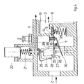
- Vorteilhafte Ausgestaltungen der Erfindung ergeben sich aus den Unteransprüchen. Sie wird nachfolgend anhand eines in den Zeichnungen wiedergegebenen Ausführungsbeispiels erläutert. Dabei zeigt
- Figur 1 das Gassicherheitsventil in der Ruhestellung, wobei sowohl das zwischen dem Einlaß des Ventilgehäuses und einem zum Hauptbrenner führenden Auslaß gelegene Sicherheitsventil als auch ein zwischen dem Einlaß und einem Zündbrenneranschluß gelegenes Zündbrennerventil geschlossen und der Elektromagnet der Zündsicherungseinrichtung stromlos ist;
- Figur 2 das Ventil im Zeitpunkt eines Zündversuches, wenn das Sicherheitsventil geschlossen, das Zündbrennerventil geöffnet und der Anker des Elektromagneten durch Handbetätigungen gegen dessen Magnetkern gedrückt ist;
- Figur 3 die Betriebsstellung des Gassicherheitsventils, in welcher sowohl das Zündbrennerventil als auch das Sicherheitsventil geöffnet ist und der Stromfluß durch den Elektromagneten den Anker der Zündsicherungseinrichtung am Magnetkern festhält;
- Figur 4 das Ventil nach einem willkürlichen Schließen von Hand, wenn der Elektromagnet noch stromdurchflossen und sein Anker deshalb noch nicht abgefallen ist.
- Das Ventilgehäuse 1 weist einen Gaseinlaß 2, einen ersten Auslaß 3, sowie einen Zündbrennerauslaß 4 auf. Der Auslaß 3 steht über ein nicht dargestelltes Hauptgasventil mit dem Hauptbrenner in Verbindung. Zwischen Einlaß 2 und Hauptauslaß 3 liegt das Sicherheitsventil, bestehend aus Ventilsitz 5 und Schließkörper 6. Der Schließkörper wird von einem zweiarmigen Hebel 7 getragen, der um eine gehäusefeste Achse 8 schwenkbar ist. Eine sich einseitig gehäusefest abstützende Schließfeder 9 drückt den Schließkörper 6 und den ihn tragenden Hebelarm 10 in Richtung auf den Ventilsitz 5.
- Eine Zündsicherungseinrichtung 11 enthält einen Elektromagneten mit Kern 12 und Anker 13. Der Anker ist von einem Ankerstift 14 getragen, an dem über einen Bund 15 eine Feder 16 angreift und den Anker 13 vom Kern 12 wegzuziehen sucht. Eine auf dem Kern 12 angebrachte Erregerwicklung 17 steht über eine Leitung 18 mit einem nicht dargestellten Thermoelement in Verbindung, welches durch die Flamme des Zündbrenners erhitzt wird. Solange die Zündflamme brennt, fließt ein vom Thermoelement gelieferter Strom durch die Erregerwicklung 17 und magnetisiert den Kern 12 des Elektromagneten 12, 13, 17 der Zündsicherungseinrichtung 11. Der Zündbrenner ist an den Zündbrennerauslaß 4 angeschlossen,und zwischen dem Zündbrenneranschluß 4. und dem Einlaß 2 des Ventilgehäuses liegt das Zündbrennerventil, bestehend aus dem Ventilsitz 19 und dem Schließkörper 20. Letzterer wird von der Betätigungsstange 21 getragen. Sie kann mittels einer Drucktaste 22 gegen die Kraft einer Rückstellfeder 23 in Pfeilrichtung eingedrückt werden. An der Betätigungsstange 21 ist um eine hierzu senkrechte Achse 38 schwenkbar eine Klinke 24 gelagert, die durch eine Feder 25 im Gegenuhrzeigersinn vorgespannt ist. Die Klinke 24 weist eine Auflauf-Schrägfläche 26, eine Ausnehmung 27, einen Vorsprung, sowie einen Anschlag 39 auf.
- Um die gehäusefeste Achse 8 ist ferner ein zweiter zweiarmiger Hebel 29 schwenkbar, dessen in der Zeichnung rechtes Ende am Ende des Ankerstifts 14 anliegt, während sein linkes Ende 30 mit der Klinke 24 zusammenarbeitet. Die Betätigungsstange 21 ist sowohl in ihrem oberen Teil als auch an ihrem freien Ende 31 im Gehäuse geführt und mit einem Bund 32 versehen, der mit dem zweiten Hebel 29 zusammenwirkt. Eine Spreizfeder 33 drückt die beiden Hebel 7 und 29 auseinander. Eine Dichtung 34 sorgt für einen gasdichten Abschluß der Betätigungsstangendurchführung durch die Gehäusewand.
- In der Ruhestellung gemäß Figur 1 ist sowohl das Sicherheitsventil 5, 6 als auch das Zündbrennerventil 19, 20 geschlossen. Der Elektromagnet 12, 17 ist stromlos und sein Anker 13 wird durch die Feder 16 vom Kern 12 weggedrückt. Damit drückt der Ankerstift 14 zugleich den zweiten Hebel 29 im Uhrzeigersinn gegen die Auflauffläche 26 der Klinke 24. Diese liegt unter der Vorspannung der Feder 25 am linken Hebelarm 30 des Hebels 29 an.
- Soll ausgehend von der in Figur 1 dargestellten Ruhestellung der an den Hauptauslaß 3 angeschlossene Brenner in Gang gesetzt werden, so muß zunächst der mit dem Zündbrenneranschluß 4 in Verbindung stehende Zündbrenner gezündet werden. Hierzu wird, wie in Figur 2 dargestellt, die Taste 22 gegen die Kraft der Rückstellfeder 23 eingedrückt und hierdurch der Schließkörper 20 des Zündbrennerventils 19, 20 vom Sitz 19 abgehoben. Damit fließt Gas über den Auslaß 4 zum Zündbrenner und kann dort entzündet werden. Beim Eindrücken der Taste 22 schwenkt der Bund 32 zugleich den zweiten Hebel 29 im Gegenuhrzeigersinn um die Achse 8, wodurch das rechte Ende des Hebels 29 den Ankerstift 14 nach oben und damit den Anker 13 gegen den Kern 12 des Elektromagneten der Zündsicherungseinrichtung 11 drückt. Die Feder 25 sorgt dafür, daß die Klinke 24 mit ihrer Auflauffläche 26 weiterhin am linken Ende 30 des zweiten Hebels 29 anliegt. Hat sich die Zündflamme gebildet, so magnetisiert der vom Thermoelement erzeugte Strom durch die Erregerwicklung 17 den Kern 12, so daß die Magnetkraft den Anker 13 am Kern 12 auch dann festhält, wenn die den Ankerstife 14 eindrückende Kraft des Hebels 29 wegfallen sollte.
- Dies geschieht beim Loslassen der Drucktaste 22, wenn diese, wie in Figur 3 wiedergegeben, unter der Kraft der Rückstellfeder 23 ein Stück in Richtung auf ihre Ruhestellung zurückbewegt wird. Sie erreicht nicht ganz die Ruhestellung gemäß Figur 1, sondern wird nur so weit zurückbewegt, daß das Zündbrennerventil 19, 20 offen bleibt. Bei dieser Rückbewegung aus der Stellung gemäß Figur 2 gleitet die Auflauffläche 26 vom Hebelende 30 ab, so daß die Klinke 24 durch die Feder 25 im Gegenuhrzeigersinn geschwenkt wird und der Vorsprung 28 unter das linke Ende 35 des ersten Hebels 7 greift und diesen im Uhrzeigersinn schwenkt. Er nimmt dann die aus Figur 3 ersichtliche Betriebsstellung ein, in welcher auch das Sicherheitsventil 5, 6 geöffnet ist. Nunmehr fließt Gas sowohl zum Zündbrenner als auch zum Hauptbrenner, wobei der Gasstrom zum Hauptbrenner durch ein zusätzliches nicht dargestelltes Hauptgasventil entsprechend dem Wärmebedarf geregelt werden kann. Die Rückbewegung der Betätigungsstange 21 wird durch Zusammenwirken der Anschläge 37/40 und 28/35 begrenzt. Sollte während dieses Normalbetriebs die Zündflamme erlöschen, so wird nach dem Abkühlen des Thermoelements die Erregerwicklung 17 des Elektromagneten 12, 17 stromlos und der Anker 13 durch die Feder 16 vom Kern 12 weggedrückt. Dabei schwenkt er den zweiten Hebel 29 im Uhrzeigersinn um die Achse 8. Dabei drückt das linke Ende 30 des Hebels 29 über die Auflauffläche 26 die Klinke 24 nach außen, das heißt schwenkt sie geringfügig im Uhrzeigersinn, wodurch der Vorsprung 28 sich vom linken Ende 35 des ersten Hebels 7 wegbewegt. Damit kann die Schließfeder 9 den Hebel 7 im Gegenuhrzeigersinn schwenken und den Schließkörper 6 gegen den Sitz 5 drücken. Damit ist das Sicherheitsventil 5, 6 geschlossen. Zugleich hat das Abgleiten des Vorsprungs 28 vom linken Hebelende 35 zur Folgefdaß die Betätigungstaste 21 nicht länger durch den Eingriff dieser beiden Teile von Klinke und erstem Hebel 7 festgehalten wird. Vielmehr kann die Rückstellfeder 23 die Betätigungsstange in Schließrichtung gemäß Figur 1 bewegen, so daß auch der Gasstrom zum Zündbrenner durch das Zündventil 19, 20 unterbrochen wird.
- 3 Soll von der in Figur wiedergegebenen Betriebsstellung aus das Gasventil von Hand gechlossen werden, so wird die Drucktaste 22 und mit ihr Betätigungsstange 21 und Klinke 24 geringfügig gedreht, so daß wiederum der Vorsprung 28 vom linken Ende 35 des ersten Hebels 7 abgleitet und in der soeben geschilderten Weise sowohl das Sicherheitsventil 5, 6 als auch das Zündventil 19, 20 schließt. Bei der Rückbewegung der Betätigungsstange 21 in die Ruhestellung fällt, wie Figur 4 zeigt, das linke Ende 35 des Hebels 7 in die Ausnehmung 27 der Klinke 24 ein. Damit kann die Feder 25 die Klinke 24 so weit im Uhrzeigersinn schwenken, bis der Klinkenanschlag 39 einem gehäusefesten Anschlag 36 gegenübersteht. Damit ist, wie Figur 4 zeigt, die Wiedereinschaltsperre wirksam. Die Betätigungsstange 21 kann nämlich so lange nicht eingedrückt und das Sicherheitsventil 5, 6 so lange nicht geöffnet werden, wie der Klinkenanschlag 39 dem gehäusefesten Anschlag 36 gegenübersteht. Erst wenn nach dem Abkühlen des Thermoelements die Zündsicherungeinrichtung 11 stromlos wird und den Anker 13 freigibt, kann die Rückstellfeder 16 den Ankerstift 14 nach unten drücken. Dabei gleitet das linke Ende 30 des zweiten Hebels 29 an der Auflauffläche 26 der Klinke 24 entlang und schwenkt die Klinke 24 im Uhrzeigersinn in die aus Figur 1 ersichtliche Ruhestellung. Dann stehen sich die Anschläge 39 und 36 nicht mehr gegenüber und ein erneuter Zündversuch kann, wie oben beschrieben, eingeleitet werden.
- In der Betriebsstellung gemäß Figur 3 wird, wie erwähnt, die Rückbewegung der Betätigungsstange 21 unter der Kraft der Feder 23 begrenzt durch das Anliegen des Anschlages 28 am linken Hebelende 35 des ersten Hebels 7. Die Schwenk- bewegung dieses Hebels,wiederum im Uhrzeigersinn, wird begrenzt durch einen dem rechten Hebelarm gegenüberstehenden gehäusefesten Anschlag 37.
Claims (7)
gekennzeichnet durch folgende Merkmale:
Applications Claiming Priority (2)
| Application Number | Priority Date | Filing Date | Title |
|---|---|---|---|
| DE3133075 | 1981-08-21 | ||
| DE19813133075 DE3133075A1 (de) | 1981-08-21 | 1981-08-21 | Gassicherheitsventil mit wiedereinschaltsperre |
Publications (2)
| Publication Number | Publication Date |
|---|---|
| EP0073405A1 true EP0073405A1 (de) | 1983-03-09 |
| EP0073405B1 EP0073405B1 (de) | 1984-06-27 |
Family
ID=6139781
Family Applications (1)
| Application Number | Title | Priority Date | Filing Date |
|---|---|---|---|
| EP82107467A Expired EP0073405B1 (de) | 1981-08-21 | 1982-08-17 | Gassicherheitsventil mit Wiedereinschaltsperre |
Country Status (4)
| Country | Link |
|---|---|
| US (1) | US4442853A (de) |
| EP (1) | EP0073405B1 (de) |
| DE (2) | DE3133075A1 (de) |
| DK (1) | DK150034C (de) |
Families Citing this family (31)
| Publication number | Priority date | Publication date | Assignee | Title |
|---|---|---|---|---|
| US5203688A (en) * | 1992-02-04 | 1993-04-20 | Honeywell Inc. | Safe gas control valve for use with standing pilot |
| US5193993A (en) * | 1992-02-05 | 1993-03-16 | Honeywell Inc. | Safe gas valve |
| US5622200A (en) * | 1994-04-14 | 1997-04-22 | Mertik Maxitrol Gmbh & Co., Kg | Thermo-electric safety igniter with reignition lock |
| US6886581B2 (en) | 2002-11-12 | 2005-05-03 | Uwe Harniet | Gas valve with a thermoelectric security device |
| CA2488846C (en) * | 2003-12-01 | 2010-09-21 | Platinum Energy Services Corp. | Burner ignition and control system |
| ITTO20040218A1 (it) * | 2004-04-08 | 2004-07-08 | Iusa Ind Unidas S A De C V | Dispositivo di sicurezza per valvola d'accensione di un bruciatore a gas. |
| US7624755B2 (en) * | 2005-12-09 | 2009-12-01 | Honeywell International Inc. | Gas valve with overtravel |
| US7523762B2 (en) * | 2006-03-22 | 2009-04-28 | Honeywell International Inc. | Modulating gas valves and systems |
| US20080099082A1 (en) * | 2006-10-27 | 2008-05-01 | Honeywell International Inc. | Gas valve shutoff seal |
| US7644731B2 (en) * | 2006-11-30 | 2010-01-12 | Honeywell International Inc. | Gas valve with resilient seat |
| US8899264B2 (en) | 2011-12-15 | 2014-12-02 | Honeywell International Inc. | Gas valve with electronic proof of closure system |
| US9846440B2 (en) | 2011-12-15 | 2017-12-19 | Honeywell International Inc. | Valve controller configured to estimate fuel comsumption |
| US9835265B2 (en) | 2011-12-15 | 2017-12-05 | Honeywell International Inc. | Valve with actuator diagnostics |
| US9074770B2 (en) | 2011-12-15 | 2015-07-07 | Honeywell International Inc. | Gas valve with electronic valve proving system |
| US8905063B2 (en) | 2011-12-15 | 2014-12-09 | Honeywell International Inc. | Gas valve with fuel rate monitor |
| US9557059B2 (en) | 2011-12-15 | 2017-01-31 | Honeywell International Inc | Gas valve with communication link |
| US8947242B2 (en) | 2011-12-15 | 2015-02-03 | Honeywell International Inc. | Gas valve with valve leakage test |
| US9995486B2 (en) | 2011-12-15 | 2018-06-12 | Honeywell International Inc. | Gas valve with high/low gas pressure detection |
| US8839815B2 (en) | 2011-12-15 | 2014-09-23 | Honeywell International Inc. | Gas valve with electronic cycle counter |
| US9851103B2 (en) | 2011-12-15 | 2017-12-26 | Honeywell International Inc. | Gas valve with overpressure diagnostics |
| US10422531B2 (en) | 2012-09-15 | 2019-09-24 | Honeywell International Inc. | System and approach for controlling a combustion chamber |
| US9234661B2 (en) | 2012-09-15 | 2016-01-12 | Honeywell International Inc. | Burner control system |
| EP2868970B1 (de) | 2013-10-29 | 2020-04-22 | Honeywell Technologies Sarl | Regelungsvorrichtung |
| US10024439B2 (en) | 2013-12-16 | 2018-07-17 | Honeywell International Inc. | Valve over-travel mechanism |
| US9841122B2 (en) | 2014-09-09 | 2017-12-12 | Honeywell International Inc. | Gas valve with electronic valve proving system |
| US9645584B2 (en) | 2014-09-17 | 2017-05-09 | Honeywell International Inc. | Gas valve with electronic health monitoring |
| US10503181B2 (en) | 2016-01-13 | 2019-12-10 | Honeywell International Inc. | Pressure regulator |
| US10564062B2 (en) | 2016-10-19 | 2020-02-18 | Honeywell International Inc. | Human-machine interface for gas valve |
| JP6861105B2 (ja) * | 2017-06-14 | 2021-04-21 | リンナイ株式会社 | ガス燃焼装置 |
| US11073281B2 (en) | 2017-12-29 | 2021-07-27 | Honeywell International Inc. | Closed-loop programming and control of a combustion appliance |
| US10697815B2 (en) | 2018-06-09 | 2020-06-30 | Honeywell International Inc. | System and methods for mitigating condensation in a sensor module |
Citations (5)
| Publication number | Priority date | Publication date | Assignee | Title |
|---|---|---|---|---|
| FR1519739A (fr) * | 1967-02-20 | 1968-04-05 | Theobald Ets A | Dispositif de sécurité à couple thermo-électrique pour brûleurs à gaz |
| DE1429062A1 (de) * | 1962-08-10 | 1968-10-31 | Controls Mij Europa N V | Sicherheitsventil,insbesondere fuer Gasheizungen |
| US3780600A (en) * | 1971-07-14 | 1973-12-25 | Robertshaw Controls Co | Dual lever mechanism |
| US3877475A (en) * | 1973-10-17 | 1975-04-15 | Honeywell Inc | Safe lighting gas valve |
| DE2605128A1 (de) * | 1975-02-13 | 1976-09-02 | Honeywell Inc | Gasarmatur |
Family Cites Families (5)
| Publication number | Priority date | Publication date | Assignee | Title |
|---|---|---|---|---|
| GB1084172A (de) * | ||||
| US2719531A (en) * | 1952-12-20 | 1955-10-04 | Honeywell Regulator Co | Valve |
| US2969077A (en) * | 1957-04-12 | 1961-01-24 | Controls Co Of America | Control device |
| US3572355A (en) * | 1968-03-30 | 1971-03-23 | Honeywell Inc | Pushbutton operable gas valve combination |
| US3574308A (en) * | 1969-03-07 | 1971-04-13 | Honeywell Inc | Manually reset safety control |
-
1981
- 1981-08-21 DE DE19813133075 patent/DE3133075A1/de not_active Withdrawn
-
1982
- 1982-08-17 DE DE8282107467T patent/DE3260300D1/de not_active Expired
- 1982-08-17 EP EP82107467A patent/EP0073405B1/de not_active Expired
- 1982-08-19 DK DK372682A patent/DK150034C/da not_active IP Right Cessation
- 1982-09-27 US US06/423,873 patent/US4442853A/en not_active Expired - Fee Related
Patent Citations (5)
| Publication number | Priority date | Publication date | Assignee | Title |
|---|---|---|---|---|
| DE1429062A1 (de) * | 1962-08-10 | 1968-10-31 | Controls Mij Europa N V | Sicherheitsventil,insbesondere fuer Gasheizungen |
| FR1519739A (fr) * | 1967-02-20 | 1968-04-05 | Theobald Ets A | Dispositif de sécurité à couple thermo-électrique pour brûleurs à gaz |
| US3780600A (en) * | 1971-07-14 | 1973-12-25 | Robertshaw Controls Co | Dual lever mechanism |
| US3877475A (en) * | 1973-10-17 | 1975-04-15 | Honeywell Inc | Safe lighting gas valve |
| DE2605128A1 (de) * | 1975-02-13 | 1976-09-02 | Honeywell Inc | Gasarmatur |
Also Published As
| Publication number | Publication date |
|---|---|
| DE3133075A1 (de) | 1983-03-10 |
| EP0073405B1 (de) | 1984-06-27 |
| DK150034C (da) | 1987-05-11 |
| US4442853A (en) | 1984-04-17 |
| DE3260300D1 (en) | 1984-08-02 |
| DK150034B (da) | 1986-11-24 |
| DK372682A (da) | 1983-02-22 |
Similar Documents
| Publication | Publication Date | Title |
|---|---|---|
| EP0073405B1 (de) | Gassicherheitsventil mit Wiedereinschaltsperre | |
| DE2605128C2 (de) | Gasarmatur | |
| DE2448707A1 (de) | Gasarmatur mit drehbarem hahnkueken | |
| EP1599694B1 (de) | Gasregelarmatur | |
| DE2834639A1 (de) | Sicherheits-gasventil mit wiedereinschaltsperre | |
| DE2920875C2 (de) | Zündsicherungsventil für gas- oder ölbeheizte Geräte | |
| EP0046843B1 (de) | Zündsicherungsventil für gas- oder ölbeheizte Geräte | |
| DE10008394C1 (de) | Kammerverschluss bei einem Repetiergewehr mit einer Schlagbolzensicherung | |
| DE1529049A1 (de) | Gasventil mit Sicherheitsvorrichtung | |
| DE1550313A1 (de) | Sicherheitsventil | |
| DE1778129C3 (de) | Drucktastenbetätigte Gasventilkombination | |
| DE4322732A1 (de) | Elektromagnetisch gesteuertes Sperrschloß | |
| EP0027504B1 (de) | Zündsicherungsventil für gas- oder ölbeheizte Geräte | |
| DE1811867A1 (de) | Steuer- und Sicherheitseinrichtung fuer gasbetriebene Warmwasserbereiter oder Durchlauferhitzer | |
| DE1955483C (de) | Gasbrenn vorrichtung mit thermoelektrischer Sicherheitszündvorrichtung | |
| DE1729891B2 (de) | Gasschalter mit thermoelektrischer Zuendsicherung | |
| DE1404576C (de) | Gasschalter mit einem Zündgas- und einem Hauptgasventil mit thermoelektrischer Zündsicherung | |
| DE1429094C (de) | Sicherheitsventil | |
| DE2200894A1 (de) | Betaetigungsvorrichtung fuer gasventile | |
| AT270132B (de) | Gasarmatur für brennbare Gase | |
| DE1945656C (de) | Steuervorrichtung für gasbeheizte Feuerungen | |
| DE1529049B (de) | ||
| DD209021A1 (de) | Thermoelektrische zuendsicherung mit wiedereinschaltverrieglung | |
| DE2311452A1 (de) | Thermoelektrische zuendsicherung | |
| DE2313592A1 (de) | Gasarmatur zum freigeben oder absperren der gaszufuhr zum brenner eines gasbeheizten geraetes |
Legal Events
| Date | Code | Title | Description |
|---|---|---|---|
| PUAI | Public reference made under article 153(3) epc to a published international application that has entered the european phase |
Free format text: ORIGINAL CODE: 0009012 |
|
| AK | Designated contracting states |
Designated state(s): BE DE FR GB IT NL |
|
| 17P | Request for examination filed |
Effective date: 19830126 |
|
| ITF | It: translation for a ep patent filed | ||
| GRAA | (expected) grant |
Free format text: ORIGINAL CODE: 0009210 |
|
| AK | Designated contracting states |
Designated state(s): BE DE FR GB IT NL |
|
| PGFP | Annual fee paid to national office [announced via postgrant information from national office to epo] |
Ref country code: FR Payment date: 19840711 Year of fee payment: 3 |
|
| REF | Corresponds to: |
Ref document number: 3260300 Country of ref document: DE Date of ref document: 19840802 |
|
| ET | Fr: translation filed | ||
| PLBE | No opposition filed within time limit |
Free format text: ORIGINAL CODE: 0009261 |
|
| STAA | Information on the status of an ep patent application or granted ep patent |
Free format text: STATUS: NO OPPOSITION FILED WITHIN TIME LIMIT |
|
| 26N | No opposition filed | ||
| PGFP | Annual fee paid to national office [announced via postgrant information from national office to epo] |
Ref country code: BE Payment date: 19890828 Year of fee payment: 8 |
|
| PG25 | Lapsed in a contracting state [announced via postgrant information from national office to epo] |
Ref country code: FR Effective date: 19900427 |
|
| REG | Reference to a national code |
Ref country code: FR Ref legal event code: ST |
|
| PG25 | Lapsed in a contracting state [announced via postgrant information from national office to epo] |
Ref country code: BE Effective date: 19900831 |
|
| BERE | Be: lapsed |
Owner name: HONEYWELL B.V. Effective date: 19900831 |
|
| PGFP | Annual fee paid to national office [announced via postgrant information from national office to epo] |
Ref country code: NL Payment date: 19910831 Year of fee payment: 10 |
|
| ITTA | It: last paid annual fee | ||
| PG25 | Lapsed in a contracting state [announced via postgrant information from national office to epo] |
Ref country code: NL Effective date: 19930301 |
|
| NLV4 | Nl: lapsed or anulled due to non-payment of the annual fee | ||
| PGFP | Annual fee paid to national office [announced via postgrant information from national office to epo] |
Ref country code: GB Payment date: 19930623 Year of fee payment: 12 |
|
| PGFP | Annual fee paid to national office [announced via postgrant information from national office to epo] |
Ref country code: DE Payment date: 19930626 Year of fee payment: 12 |
|
| PG25 | Lapsed in a contracting state [announced via postgrant information from national office to epo] |
Ref country code: GB Effective date: 19940817 |
|
| GBPC | Gb: european patent ceased through non-payment of renewal fee |
Effective date: 19940817 |
|
| PG25 | Lapsed in a contracting state [announced via postgrant information from national office to epo] |
Ref country code: DE Effective date: 19950503 |