EP0073439A2 - Dispositif pour retenir des objets en forme de feuilles, en particulier planche à dessin ou bloc d'enregistrement - Google Patents
Dispositif pour retenir des objets en forme de feuilles, en particulier planche à dessin ou bloc d'enregistrement Download PDFInfo
- Publication number
- EP0073439A2 EP0073439A2 EP82107672A EP82107672A EP0073439A2 EP 0073439 A2 EP0073439 A2 EP 0073439A2 EP 82107672 A EP82107672 A EP 82107672A EP 82107672 A EP82107672 A EP 82107672A EP 0073439 A2 EP0073439 A2 EP 0073439A2
- Authority
- EP
- European Patent Office
- Prior art keywords
- printing paper
- cover plate
- paper
- current
- sheet
- Prior art date
- Legal status (The legal status is an assumption and is not a legal conclusion. Google has not performed a legal analysis and makes no representation as to the accuracy of the status listed.)
- Withdrawn
Links
Images


Classifications
-
- B—PERFORMING OPERATIONS; TRANSPORTING
- B43—WRITING OR DRAWING IMPLEMENTS; BUREAU ACCESSORIES
- B43L—ARTICLES FOR WRITING OR DRAWING UPON; WRITING OR DRAWING AIDS; ACCESSORIES FOR WRITING OR DRAWING
- B43L5/00—Drawing boards
- B43L5/02—Drawing boards having means for clamping sheets of paper thereto
Definitions
- the invention relates to a device for holding sheet-like objects, in particular a drawing board, consisting of a multilayer structure comprising flat and interconnected top and bottom plates with carrier layers arranged therebetween.
- the field of use of a device according to the present invention relates to the holding of sheet-like objects, e.g. Papers, foils and the like, as a drawing board, as an organization board, as a table top for a flat table plotter, as a suction wall in repro cameras, in paper and textile processing, e.g. as a brake, spreading surface, etc.
- sheet-like objects e.g. Papers, foils and the like
- the invention has the object of developing such a device in such a way that the sheet-like object is fastened over a large area to the drawing board without the need for disruptive mechanical holding devices which protrude beyond the surface of the drawing board.
- the invention is characterized in that the sheet-shaped object is held by an electrostatic force which is generated by applying a negative DC voltage to an electrically conductive printing paper arranged in the cover plate.
- An essential feature of the present invention is therefore the holding of the drawing sheet with an electrostatic force that is generated over the entire surface of the drawing board. As a result, a large holding force, as seen across the surface of the drawing board, is applied to the drawing sheet, which therefore not only adheres firmly to the top plate of the drawing board, but also in the entire support area.
- a corresponding structure of the top and bottom plates and the intermediate layer arranged between them which consists of a plastic honeycomb structure made of ABS plastic, results in an absolute parallelism of the top and bottom plates and an absolute flat cover plate so that drawing sheets can be labeled with the highest precision because of the flat surface.
- the current-conducting printing paper consists of an alpha cellulose paper which is impregnated with phenol and melamine resin and which is printed with a current-conducting conductor track in the screening or rotary process.
- the structure of the printing paper according to the invention from the materials mentioned ensures the stability of the print even in the subsequent pressing, if the printing paper is bound between the corresponding carrier and cover layers and is pressed under heat and high pressure. There is no leakage and fraying of the conductive conductors.
- the current-conducting conductor track is applied by screen printing and consists of graphite paint or silver nitrate paint.
- the product Grapharol 114 which is based on acrylate and is mixed with graphite conductive pigments, is preferably used as the graphite paint.
- the use of a silver nitrate paint is also possible. Both color compositions have the above-mentioned advantage, namely that running and fraying of the conductor tracks is avoided even when the printing paper is incorporated into the intended cover and carrier layers in the hot press process.
- the electrically conductive printing paper is impregnated in the direction of the drawing sheet by a carrier layer made of alpha cellulose paper with phenolic and melamine resin and ink fabric is covered.
- This carrier layer must have a relatively high dielectric strength in order to avoid a breakdown of the voltage in the direction of the drawing sheet. Dyes are added so that the conductive paper is not visible from above when viewed from the drawing sheet. Instead of using a dye with which the carrier layer is colored, it is also possible, according to the subject matter of claim 5, that the carrier layer is connected to a printing film with a printed millimeter grid, so that the millimeter grid is passed through the drawing sheet can see and use this as a guide.
- the current-conducting printing paper is covered according to the subject matter of claim 6 in the direction of the base plate by a plurality of support layers which are layered one above the other, each of which consists of a phenolic resin-impregnated sodium kraft paper.
- the entire cover plate consists of a cover layer, a support layer arranged underneath, the printing paper below it and the support layers arranged under the printing paper, is pressed using the hot press method, resulting in a finished thickness of approximately 1.4 mm.
- a drawing board according to the present invention is constructed according to the subject matter of claim 6 from a cover plate and a similar base plate, the base plate with the exception of the use of Printing paper identical to how the cover plate is constructed.
- a drawing board 1 is shown schematically, which consists of a cover plate 2, a honeycomb-shaped intermediate layer 4 and a bottom plate 4.
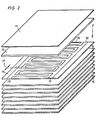
- the composition of the cover plate 2 is shown in FIG. 2, while the base plate 3 is constructed identically to the cover plate 2 with the only exception that the printing paper 15 or 25 is omitted.
- the honeycomb-shaped intermediate layer consists of an ABS plastic with, for example, hexagonally shaped, tubular honeycombs, which are open at the top and bottom, with the top of this intermediate layer with the help of an epoxy adhesive (for example a two-component adhesive Araldit 106) is glued to the underside of the cover plate 2, analogously to how the base plate 3 is glued to the underside of this intermediate view 4 as well.
- an epoxy adhesive for example a two-component adhesive Araldit 106
- a drawing sheet 8 is drawn schematically at a distance from the cover plate 2 in order to show the field lines 9 which arise along the entire surface of the cover plate and are directed perpendicular to the surface of the cover plate 2.
- the drawing sheet 8 is thereby drawn in the direction of the arrows 10 to the surface 5 of the cover plate 2 and adheres there with high adhesive force, the magnitude of the adhesive force depending on the level of the DC voltage generated by a DC voltage generator 6.
- a negative DC voltage of 5000 volts is preferably generated, which is applied to the printing paper 15 shown in FIG. 2 via corresponding connections 7.
- This high voltage is applied to the printing paper 15 shown in FIG. 2, specifically to connection points 16 of the intermeshing comb-shaped conductor tracks 18, 19, which are not shown in detail.
- the conductor tracks 18, 19 are integrated in the multilayer laminate of the cover plate 2 using the screen printing method.
- the carrier layer 13 over the printing paper is based on a condensate melamine + formaldehyde.
- the DC voltage applied creates an electrostatic adhesive force through interaction in the drawing sheet to be held.
- the drawing sheet 8 causes a short line of force. Due to the connection at the negative high voltage, negative ions emerge from the surface 5 of the cover layer 2, which simultaneously neutralize this drawing sheet 8 when the drawing sheet 8 is pulled off.
- the electronics also have space in the drawing board, so that the DC voltage generator 6 itself is integrated in the drawing board.
- the cover layer 11 arranged above the support layer 13 consists of a condensate melamine + formaldehyde, while the support layers 14 arranged below the printing paper 15 consist of a condensate phenol + formaldehyde.
- the distance 17 of the conductor tracks 18, 19 is selected from one another in such a way that there is no internal breakdown in the area of the printing paper 15.
- FIG. 3 shows a further embodiment of a cover plate 12, in which case a printing paper 15 according to FIG. 2 can be integrated there; however, it is also possible to omit the high-voltage printing paper 15 and instead only provide one printing paper 25 with conductor tracks 2 0 , 21 which are designed as resistance heating.
- the same numbers denote the same layers, so that it can be seen that the resistance-heatable printing paper 25 is bound up and down by an equal number of carrier layers 14.
- the top layer of the carrier layer 14 is followed by a further carrier layer 13 with the features described previously with reference to FIG. 2, while the carrier layer 13 is closed at the top by the cover layer 11.
Landscapes
- Printing Methods (AREA)
- Laminated Bodies (AREA)
- Electrostatic Spraying Apparatus (AREA)
- Feeding Of Articles By Means Other Than Belts Or Rollers (AREA)
- Packaging For Recording Disks (AREA)
Applications Claiming Priority (2)
| Application Number | Priority Date | Filing Date | Title |
|---|---|---|---|
| DE19813133367 DE3133367A1 (de) | 1981-08-24 | 1981-08-24 | Vorrichtung zur halterung blattfoermiger gegenstaende, insbesondere zeichenbrett oder registrierplatte |
| DE3133367 | 1981-08-24 |
Publications (2)
| Publication Number | Publication Date |
|---|---|
| EP0073439A2 true EP0073439A2 (fr) | 1983-03-09 |
| EP0073439A3 EP0073439A3 (fr) | 1985-11-13 |
Family
ID=6139959
Family Applications (1)
| Application Number | Title | Priority Date | Filing Date |
|---|---|---|---|
| EP82107672A Withdrawn EP0073439A3 (fr) | 1981-08-24 | 1982-08-21 | Dispositif pour retenir des objets en forme de feuilles, en particulier planche à dessin ou bloc d'enregistrement |
Country Status (4)
| Country | Link |
|---|---|
| EP (1) | EP0073439A3 (fr) |
| JP (1) | JPS5858879A (fr) |
| AU (1) | AU554837B2 (fr) |
| DE (1) | DE3133367A1 (fr) |
Cited By (1)
| Publication number | Priority date | Publication date | Assignee | Title |
|---|---|---|---|---|
| GB2544883A (en) * | 2015-10-27 | 2017-05-31 | Js Design Pro Ltd | Improvements in drawing boards |
Families Citing this family (3)
| Publication number | Priority date | Publication date | Assignee | Title |
|---|---|---|---|---|
| DE4017786C1 (fr) * | 1990-06-01 | 1991-10-02 | Lichtenstein Ltd., Gibraltar, Gi | |
| DE4119526A1 (de) * | 1991-06-13 | 1992-12-17 | Lichtenstein Ltd | Hochspannungsfuehrender maeander, insbesondere fuer eine elektrostatisch aufladbare haftplatte |
| DE4410091C2 (de) * | 1994-03-24 | 2003-01-09 | Helmut Woll | Verfahren zum Herstellen von elektrostatischen Hafttafeln |
Family Cites Families (12)
| Publication number | Priority date | Publication date | Assignee | Title |
|---|---|---|---|---|
| US2810232A (en) * | 1953-11-12 | 1957-10-22 | Jr Horace Fletcher | Dull finish laminated drawing board cover |
| GB996598A (en) * | 1961-09-04 | 1965-06-30 | Mason & Sons Ltd E N | Improvements in and relating to drawing boards |
| DE1284534B (fr) * | 1963-06-26 | 1968-12-05 | ||
| DE1203969B (de) * | 1963-08-16 | 1965-10-28 | F L Moseley Company | Einrichtung zur Halterung eines blattfoermigen Materials durch elektrostatische Anziehungskraefte |
| US3359469A (en) * | 1964-04-23 | 1967-12-19 | Simco Co Inc | Electrostatic pinning method and copyboard |
| DE1261777B (de) * | 1965-11-20 | 1968-02-22 | Dr Reiner Jordan | Magnetische Aufspannvorrichtung fuer Zeichengeraete auf Zeichentischen |
| DE1944179C3 (de) * | 1969-08-30 | 1975-06-05 | Watanabe Instruments Corp., Tokio | Vorrichtung zur elektrostatischen Haftung von Registrierpapier |
| DE1957657B1 (de) * | 1969-11-17 | 1971-03-25 | Licentia Gmbh | Aufspannvorrichtung |
| US3916270A (en) * | 1974-05-02 | 1975-10-28 | Tektronix Inc | Electrostatic holddown apparatus |
| DE2503818A1 (de) * | 1975-01-30 | 1976-08-05 | Burger Dierk | Zeichenbrett |
| DE3042460A1 (de) * | 1980-11-11 | 1982-06-24 | Artur 5650 Solingen Lange | Beheizte auflage fuer zeichentische |
| DE3124316C2 (de) * | 1981-06-20 | 1984-10-18 | Hartmut 8880 Dillingen Buckel | Zeichenvorrichtung |
-
1981
- 1981-08-24 DE DE19813133367 patent/DE3133367A1/de not_active Ceased
-
1982
- 1982-08-21 EP EP82107672A patent/EP0073439A3/fr not_active Withdrawn
- 1982-08-24 JP JP14557882A patent/JPS5858879A/ja active Pending
- 1982-09-10 AU AU88304/82A patent/AU554837B2/en not_active Expired - Fee Related
Cited By (1)
| Publication number | Priority date | Publication date | Assignee | Title |
|---|---|---|---|---|
| GB2544883A (en) * | 2015-10-27 | 2017-05-31 | Js Design Pro Ltd | Improvements in drawing boards |
Also Published As
| Publication number | Publication date |
|---|---|
| DE3133367A1 (de) | 1985-04-25 |
| AU554837B2 (en) | 1986-09-04 |
| AU8830482A (en) | 1984-03-15 |
| JPS5858879A (ja) | 1983-04-07 |
| EP0073439A3 (fr) | 1985-11-13 |
Similar Documents
| Publication | Publication Date | Title |
|---|---|---|
| DE3502990C1 (de) | Mehrschichtiger Flocktransferfolien-Zuschnitt | |
| WO1999017940A1 (fr) | Dispositif en papier plie a fixer sur une surface | |
| DE69115625T2 (de) | Anzeigeplakat | |
| DE3781859T2 (de) | Selbstklebender gegenstand. | |
| EP0073439A2 (fr) | Dispositif pour retenir des objets en forme de feuilles, en particulier planche à dessin ou bloc d'enregistrement | |
| DE3916099A1 (de) | Verfahren zur herstellung von dekorativen schichtpressstoffplatten | |
| DE3614541A1 (de) | Vorrichtung zum festhalten von zwischenlagen an zylindern von rotationsdruckmaschinen | |
| DE2231086A1 (de) | Flaechenheizelemente | |
| DE3415672A1 (de) | Mehrfachschalter | |
| EP0575722A2 (fr) | Stratifié décoratif à haute pression | |
| EP0249717A1 (fr) | Support changeable pour porteur d'information | |
| DE3140292C2 (de) | Verfahren zur Herstellung eines farbigen Reliefs auf einem plattenförmigen, faserverstärkten, kunststoffhaltigen Dekorkörper | |
| EP0634282A1 (fr) | Méthode pour la fabrication d'un film anti-copie | |
| DE855408C (de) | Biegsame Flachdruckplatte | |
| DE2708910C3 (de) | Mehrfach- insbesondere Endlossatz | |
| DE2437596C3 (fr) | ||
| DE2822443C2 (de) | Planungselement aus transparenter mit glatter Oberfläche versehener weicher Haftfolie | |
| DE2536233C3 (de) | Einrichtung zum Pressen von plattenförmigen! Preßgut im Zuge der Herstellung von Spanplatten, Faserplatten, Kunststofflaminatplatten u.dgl. in Paketpressen | |
| DE1259430B (de) | Verfahren zur Herstellung gedruckter Schaltungen durch Auflegen einer Metallfolie auf eine elastische Unterlage | |
| DE1805204A1 (de) | Anordnung und Verfahren zur Herstellung von Mehrfarbendrucken | |
| DE19860034A1 (de) | Verfahren und Vorrichtung zur Herstellung eines gefalzten Druckproduktes | |
| DE1292625B (de) | Kartenfoermiger Aufzeichnungstraeger mit einem Fensterausschnitt | |
| DE2902690A1 (de) | Vervielfaeltigungs-schablonenblatt | |
| DE7834977U1 (de) | Block aus bedruckten blaettern oder unbedruckten zum beschreiben oder bemalen | |
| DE7704878U1 (de) | Sammelalbum |
Legal Events
| Date | Code | Title | Description |
|---|---|---|---|
| PUAI | Public reference made under article 153(3) epc to a published international application that has entered the european phase |
Free format text: ORIGINAL CODE: 0009012 |
|
| AK | Designated contracting states |
Designated state(s): AT BE CH DE FR GB IT LI LU NL SE |
|
| 17P | Request for examination filed |
Effective date: 19840322 |
|
| PUAL | Search report despatched |
Free format text: ORIGINAL CODE: 0009013 |
|
| AK | Designated contracting states |
Designated state(s): AT BE CH DE FR GB IT LI LU NL SE |
|
| STAA | Information on the status of an ep patent application or granted ep patent |
Free format text: STATUS: THE APPLICATION IS DEEMED TO BE WITHDRAWN |
|
| 18D | Application deemed to be withdrawn |
Effective date: 19870303 |
|
| RIN1 | Information on inventor provided before grant (corrected) |
Inventor name: WERDER, HANSRUDOLF |