EP0073476B1 - Ventilatorverkleidung - Google Patents
Ventilatorverkleidung Download PDFInfo
- Publication number
- EP0073476B1 EP0073476B1 EP82107826A EP82107826A EP0073476B1 EP 0073476 B1 EP0073476 B1 EP 0073476B1 EP 82107826 A EP82107826 A EP 82107826A EP 82107826 A EP82107826 A EP 82107826A EP 0073476 B1 EP0073476 B1 EP 0073476B1
- Authority
- EP
- European Patent Office
- Prior art keywords
- fan
- radiator
- fan shroud
- shroud
- air guide
- Prior art date
- Legal status (The legal status is an assumption and is not a legal conclusion. Google has not performed a legal analysis and makes no representation as to the accuracy of the status listed.)
- Expired
Links
Images
Classifications
-
- F—MECHANICAL ENGINEERING; LIGHTING; HEATING; WEAPONS; BLASTING
- F01—MACHINES OR ENGINES IN GENERAL; ENGINE PLANTS IN GENERAL; STEAM ENGINES
- F01P—COOLING OF MACHINES OR ENGINES IN GENERAL; COOLING OF INTERNAL-COMBUSTION ENGINES
- F01P11/00—Component parts, details, or accessories not provided for in, or of interest apart from, groups F01P1/00 - F01P9/00
- F01P11/10—Guiding or ducting cooling-air, to, or from, liquid-to-air heat exchangers
-
- F—MECHANICAL ENGINEERING; LIGHTING; HEATING; WEAPONS; BLASTING
- F01—MACHINES OR ENGINES IN GENERAL; ENGINE PLANTS IN GENERAL; STEAM ENGINES
- F01P—COOLING OF MACHINES OR ENGINES IN GENERAL; COOLING OF INTERNAL-COMBUSTION ENGINES
- F01P5/00—Pumping cooling-air or liquid coolants
- F01P5/02—Pumping cooling-air; Arrangements of cooling-air pumps, e.g. fans or blowers
- F01P5/06—Guiding or ducting air to, or from, ducted fans
Definitions
- the present invention relates to a fan shroud arranged in the rear of a radiator of an automotive engine comprising a ventilation opening in which a cooling fan is disposed to draw air through the radiator and an air guide means positioned rearwardly of the radiator.
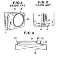
- Figs. 1 and 2 show an example of a fan shroud 10 arranged in the rear of a radiator 12 of a water- cooled automotive engine 14.
- a cooling fan 16 is shrouded by the fan shroud 10 to increase the cooling system efficiency.
- the fan shroud 10 is rectangular in external shape in accordance with the shape of a radiator core (not shown) and has a ventilation opening 18 in which the cooling fan 16 is disposed to draw air through the radiator 12.
- the fan shroud 10 is formed with a short cylindrical flange 20 which is uniform in diameter.
- Another disadvantage is that the amount of air to be supplied to the constituent parts of the engine 14 such as an oil pan and an exhaust manifold for cooling same is reduced since part of the air that has passed through the radiator 12 is allowed to flow radially of the cooling fan 16 and thus deflected away from those parts.
- a similar fan shroud arrangement is known from EP-A-0026997, disclosing a cooling fan with an inlet shroud attached to the tips of the fan blades.
- the cooling fan including the inner fan shroud at the tips of the fan blades is fitted rotatably within a fixed shroud secured to an engine cooling radiator.
- the outer fixed shroud exhibits a cylindrical ejector portion extending axially rearwards by a predetermined length beyond said fan blades in order to block a recirculation passage formed by the clearance between the fixed and rotatable shrouds by a portion of the discharged air stream.
- the claimed invention has been designed to effectively increase the efficiency of the cooling system of an automotive vehicle in accordance with the preamble of the claim and to prevent the air which has been heated during its passage through the radiator from being circulated back to the front of the radiator as well as to increase the amount of air to be supplied to the constituent parts of the engine.
- the invention aims at a less complicated fan shroud which is easy to manufacture and to assemble to the engine cooling system.
- an air guide means is formed by an air guide ring projecting integrally rearwards from the intermediate portion of the fan shroud radially spaced from the flange portion thereof.
- a free annular rear edge of the air guide ring projects more rearwards than an annular near edge of the flange portion of the fan shroud.
- the air guide ring deflects axially air which is going to escape radially from the cooling fan after having been sucked through the radiator.
- the fan shroud according to this invention is quite easy to manufacture as a single piece by injection molding, and is effective in deflecting air axially rearwards of the cooling fan. Hence, the amount of air being supplied to the constituent parts of the engine such as the oil pan and the exhaust manifold is remarkably increased.
- a fan shroud according to an embodiment of the present invention is indicated at 22 and shown to comprise a ventilation opening 24 and a short cylindrical flange 26 provided to the periphery of the ventilation opening 24 in a manner to project rearwardly therefrom.
- the fan shroud 22 further comprises an air guide means 28 provided to the rear of the fan shroud 22 for deflecting air that is going to escape radially of a cooling fan (not shown) which is disposed in the ventilation opening 24.
- the air guide means 28 comprises an air guide ring 30 placed around the cylindrical flange 26 at a predetermined space in between.
- the air guide ring 30 has a front end joined directly with the fan shroud 22 proper and a rear free end projecting more rearwards than that of the cylindrical flange 26, i.e. the air guide ring projects integrally rearwards from an inclined intermediate portion of fan shroud 22 and the fan shroud 22 is formed into a single piece from a synthetic resinous material by injection molding.
- air that is going to escape radially of the cooling fan after having passed through the radiator 12 is efficiently deflected rearwardly of the radiator 12 making it possible to prevent the air that has been heated during its passage through the radiator 12 from being recirculated back to the front of the radiator 12 as well as to increase the amount of air to be supplied to the constituent parts of the engine such as the oil pan and the exhaust manifold.
Landscapes
- Engineering & Computer Science (AREA)
- Chemical & Material Sciences (AREA)
- Combustion & Propulsion (AREA)
- Mechanical Engineering (AREA)
- General Engineering & Computer Science (AREA)
- Cooling, Air Intake And Gas Exhaust, And Fuel Tank Arrangements In Propulsion Units (AREA)
- Structures Of Non-Positive Displacement Pumps (AREA)
Claims (1)
- Stationäre Lüfterhaube (22), die an der Rückseite eines Kühlers (12) eines Kraftfahrzeugmotors (14) angeordnet ist, mit einem Einlaßabschnitt, dessen Querschnitt im wesentlichen dem zugehörigen Querschnitt des Kühlers (12) entspricht, einem Zwischenabschnitt mit allmählich abnehmendem Querschnitt und einem Flanschabschnitt (26) am hinteren Ende der Lüfterhaube (22), der eine Lüftungsöffnung (24) zur Aufnahme eines Kühllüfters (16) aufweist, wobei die Lüfterhaube (22) eine Luftführungseinrichtung (28) an der Rückseite des Kühlers (12) bildet, dadurch gekennzeichnet, daß die Luftführungseinrichtung (28) durch einen Luftführungsring (30) gebildet ist, der einstückig von dem Zwischenabschnitt der Lüfterhaube (22) nach hinten in radialem Abstand von dem Flanschabschnitt (24) der Lüfterhaube hervorsteht, wobei eine freie, ringförmige Hinterkante der Luftführungsringes (30) weiter nach hinten hervorsteht als eine ringförmige Hinterkante des Flanschabschnittes (26) der Lüfterhaube (22).
Applications Claiming Priority (2)
| Application Number | Priority Date | Filing Date | Title |
|---|---|---|---|
| JP13664181A JPS5838319A (ja) | 1981-08-31 | 1981-08-31 | フアンシユラウド |
| JP136641/81 | 1981-08-31 |
Publications (3)
| Publication Number | Publication Date |
|---|---|
| EP0073476A2 EP0073476A2 (de) | 1983-03-09 |
| EP0073476A3 EP0073476A3 (en) | 1983-08-10 |
| EP0073476B1 true EP0073476B1 (de) | 1986-12-17 |
Family
ID=15180054
Family Applications (1)
| Application Number | Title | Priority Date | Filing Date |
|---|---|---|---|
| EP82107826A Expired EP0073476B1 (de) | 1981-08-31 | 1982-08-25 | Ventilatorverkleidung |
Country Status (3)
| Country | Link |
|---|---|
| EP (1) | EP0073476B1 (de) |
| JP (1) | JPS5838319A (de) |
| DE (1) | DE3274750D1 (de) |
Families Citing this family (7)
| Publication number | Priority date | Publication date | Assignee | Title |
|---|---|---|---|---|
| DE3431801C1 (de) * | 1984-08-30 | 1985-10-17 | Daimler-Benz Ag | Luftfoerdereinrichtung an einem Kuehler fuer wassergekuehlte Brennkraftmaschine |
| JPS63314398A (ja) * | 1987-06-18 | 1988-12-22 | Matsushita Electric Ind Co Ltd | 電気機器の送風装置 |
| DE3804217A1 (de) * | 1988-02-11 | 1989-08-24 | Bosch Gmbh Robert | Axialluefter |
| US7331759B1 (en) | 2004-03-04 | 2008-02-19 | Bou-Matic Technologies Corporation | Drying fan |
| BRPI0510174B1 (pt) * | 2004-04-22 | 2016-04-26 | Chevron Phillips Chemical Co | método para preparação de um catalisador de polimerização, catalisador, composição catalisadora para polimerização de olefinas, método de uso do catalisador e para produção de um polímero, polímero e resina |
| FR2884182B1 (fr) | 2005-04-06 | 2008-11-28 | Faurecia Bloc Avant | Element de canalisation pour bloc avant de vehicule automobile, bloc avant et carenage associes. |
| US8579582B1 (en) | 2006-03-21 | 2013-11-12 | Technologies Holdings Corp. | Efficient drying fan |
Citations (1)
| Publication number | Priority date | Publication date | Assignee | Title |
|---|---|---|---|---|
| EP0026997A1 (de) * | 1979-10-09 | 1981-04-15 | General Motors Corporation | Luftführung für Motorkühlgebläse |
Family Cites Families (4)
| Publication number | Priority date | Publication date | Assignee | Title |
|---|---|---|---|---|
| US3635285A (en) * | 1970-05-11 | 1972-01-18 | Gen Motors Corp | Cooling fan |
| JPS5117738A (en) * | 1974-07-31 | 1976-02-12 | Isuzu Motors Ltd | Enjinno reikyakusochi |
| US3937192A (en) * | 1974-09-03 | 1976-02-10 | General Motors Corporation | Ejector fan shroud arrangement |
| US4061188A (en) * | 1975-01-24 | 1977-12-06 | International Harvester Company | Fan shroud structure |
-
1981
- 1981-08-31 JP JP13664181A patent/JPS5838319A/ja active Pending
-
1982
- 1982-08-25 EP EP82107826A patent/EP0073476B1/de not_active Expired
- 1982-08-25 DE DE8282107826T patent/DE3274750D1/de not_active Expired
Patent Citations (1)
| Publication number | Priority date | Publication date | Assignee | Title |
|---|---|---|---|---|
| EP0026997A1 (de) * | 1979-10-09 | 1981-04-15 | General Motors Corporation | Luftführung für Motorkühlgebläse |
Also Published As
| Publication number | Publication date |
|---|---|
| JPS5838319A (ja) | 1983-03-05 |
| EP0073476A3 (en) | 1983-08-10 |
| DE3274750D1 (en) | 1987-01-29 |
| EP0073476A2 (de) | 1983-03-09 |
Similar Documents
| Publication | Publication Date | Title |
|---|---|---|
| US5180279A (en) | Heat shield and deflector for engine cooling fan motor | |
| US5423660A (en) | Fan inlet with curved lip and cylindrical member forming labyrinth seal | |
| EP0820557B1 (de) | Ventilatorverkleidung | |
| US4979584A (en) | Automotive vehicle engine bay ventilation | |
| EP0026997B1 (de) | Luftführung für Motorkühlgebläse | |
| US5495909A (en) | Automotive vehicle engine bay ventilation by ducted-fan-operated ejector | |
| CN100451348C (zh) | 离心式鼓风机 | |
| US6283726B1 (en) | Radial blower, particularly for heating and air conditioning systems in automobiles | |
| US3937192A (en) | Ejector fan shroud arrangement | |
| EP0347036B1 (de) | Zarge für Motorkühllüfter | |
| US5590624A (en) | Engine cooling systems | |
| US4396351A (en) | Engine cooling fan | |
| US20010004011A1 (en) | Cooling device for radiator of motorcycle | |
| GB2037890A (en) | Cooling system for internal combustion engines | |
| EP0073476B1 (de) | Ventilatorverkleidung | |
| US4211514A (en) | Mixed flow fan | |
| JP2000513067A (ja) | ラジアルベンチレーター | |
| CA1036447A (en) | Recirculation barrier for a heat transfer system | |
| JP3539316B2 (ja) | ラジエータ用ファンシュラウド | |
| EP0992692A1 (de) | Lüfter mit Kühlkanal für den Motor | |
| JPH034582Y2 (de) | ||
| CN220539952U (zh) | 一种离心风机以及应用有该离心风机的吸油烟机 | |
| CA1044972A (en) | Combination fan shroud and toroidal radiator | |
| US20260098497A1 (en) | Injector for de-icing device for an air intake of an aircraft turbojet nacelle, and associated method | |
| KR200376811Y1 (ko) | 팬과 쉬라우드 조립체 |
Legal Events
| Date | Code | Title | Description |
|---|---|---|---|
| PUAI | Public reference made under article 153(3) epc to a published international application that has entered the european phase |
Free format text: ORIGINAL CODE: 0009012 |
|
| 17P | Request for examination filed |
Effective date: 19820825 |
|
| AK | Designated contracting states |
Designated state(s): DE FR GB |
|
| PUAL | Search report despatched |
Free format text: ORIGINAL CODE: 0009013 |
|
| AK | Designated contracting states |
Designated state(s): DE FR GB |
|
| RAP1 | Party data changed (applicant data changed or rights of an application transferred) |
Owner name: NISSAN MOTOR CO., LTD. |
|
| GRAA | (expected) grant |
Free format text: ORIGINAL CODE: 0009210 |
|
| AK | Designated contracting states |
Kind code of ref document: B1 Designated state(s): DE FR GB |
|
| PG25 | Lapsed in a contracting state [announced via postgrant information from national office to epo] |
Ref country code: FR Free format text: THE PATENT HAS BEEN ANNULLED BY A DECISION OF A NATIONAL AUTHORITY Effective date: 19861217 |
|
| REF | Corresponds to: |
Ref document number: 3274750 Country of ref document: DE Date of ref document: 19870129 |
|
| EN | Fr: translation not filed | ||
| PLBE | No opposition filed within time limit |
Free format text: ORIGINAL CODE: 0009261 |
|
| STAA | Information on the status of an ep patent application or granted ep patent |
Free format text: STATUS: NO OPPOSITION FILED WITHIN TIME LIMIT |
|
| 26N | No opposition filed | ||
| PG25 | Lapsed in a contracting state [announced via postgrant information from national office to epo] |
Ref country code: DE Effective date: 19890503 |
|
| PG25 | Lapsed in a contracting state [announced via postgrant information from national office to epo] |
Ref country code: GB Effective date: 19890825 |
|
| GBPC | Gb: european patent ceased through non-payment of renewal fee |