EP0073498B1 - Verfahren zum Trocknen von zu verkokenden Kohlen - Google Patents
Verfahren zum Trocknen von zu verkokenden Kohlen Download PDFInfo
- Publication number
- EP0073498B1 EP0073498B1 EP82107903A EP82107903A EP0073498B1 EP 0073498 B1 EP0073498 B1 EP 0073498B1 EP 82107903 A EP82107903 A EP 82107903A EP 82107903 A EP82107903 A EP 82107903A EP 0073498 B1 EP0073498 B1 EP 0073498B1
- Authority
- EP
- European Patent Office
- Prior art keywords
- heat medium
- heat
- coal
- moisture content
- drier
- Prior art date
- Legal status (The legal status is an assumption and is not a legal conclusion. Google has not performed a legal analysis and makes no representation as to the accuracy of the status listed.)
- Expired
Links
Images

Classifications
-
- C—CHEMISTRY; METALLURGY
- C10—PETROLEUM, GAS OR COKE INDUSTRIES; TECHNICAL GASES CONTAINING CARBON MONOXIDE; FUELS; LUBRICANTS; PEAT
- C10B—DESTRUCTIVE DISTILLATION OF CARBONACEOUS MATERIALS FOR PRODUCTION OF GAS, COKE, TAR, OR SIMILAR MATERIALS
- C10B57/00—Other carbonising or coking processes; Features of destructive distillation processes in general
- C10B57/08—Non-mechanical pretreatment of the charge, e.g. desulfurization
- C10B57/10—Drying
-
- F—MECHANICAL ENGINEERING; LIGHTING; HEATING; WEAPONS; BLASTING
- F26—DRYING
- F26B—DRYING SOLID MATERIALS OR OBJECTS BY REMOVING LIQUID THEREFROM
- F26B21/00—Arrangements for supplying or controlling air or other gases for drying solid materials or objects
- F26B21/30—Controlling, e.g. regulating, parameters of gas supply
- F26B21/35—Temperature; Pressure
-
- F—MECHANICAL ENGINEERING; LIGHTING; HEATING; WEAPONS; BLASTING
- F26—DRYING
- F26B—DRYING SOLID MATERIALS OR OBJECTS BY REMOVING LIQUID THEREFROM
- F26B23/00—Heating arrangements
- F26B23/001—Heating arrangements using waste heat
- F26B23/002—Heating arrangements using waste heat recovered from dryer exhaust gases
-
- F—MECHANICAL ENGINEERING; LIGHTING; HEATING; WEAPONS; BLASTING
- F26—DRYING
- F26B—DRYING SOLID MATERIALS OR OBJECTS BY REMOVING LIQUID THEREFROM
- F26B25/00—Details of general application not covered by group F26B21/00 or F26B23/00
- F26B25/22—Controlling the drying process in dependence on liquid content of solid materials or objects
-
- Y—GENERAL TAGGING OF NEW TECHNOLOGICAL DEVELOPMENTS; GENERAL TAGGING OF CROSS-SECTIONAL TECHNOLOGIES SPANNING OVER SEVERAL SECTIONS OF THE IPC; TECHNICAL SUBJECTS COVERED BY FORMER USPC CROSS-REFERENCE ART COLLECTIONS [XRACs] AND DIGESTS
- Y02—TECHNOLOGIES OR APPLICATIONS FOR MITIGATION OR ADAPTATION AGAINST CLIMATE CHANGE
- Y02P—CLIMATE CHANGE MITIGATION TECHNOLOGIES IN THE PRODUCTION OR PROCESSING OF GOODS
- Y02P70/00—Climate change mitigation technologies in the production process for final industrial or consumer products
- Y02P70/10—Greenhouse gas [GHG] capture, material saving, heat recovery or other energy efficient measures, e.g. motor control, characterised by manufacturing processes, e.g. for rolling metal or metal working
Definitions
- the present invention relates to a method for drying coals, particularly coking coals, by using a heat medium for exchanging the sensible heat of gas generated from coke ovens and using this heat medium containing the sensible heat as a main heat source for the drying.
- the oven gas generated during the distillation in carburization chambers passes through ascension pipes to bend pipes connected to drying means and the gas is cooled in th bend pipes by a liquor spray with ammonia liquor, then the oven gas collected in the bend pipes is further cooled down to about ordinary temperatures by gas coolers.
- the gas generated from the coke oven is usually at a temperature ranging from 600 to 800°C, but due to the lack of efficient means for recovering the heat contained in the oven gas, or due to failure in finding appropriate applications for the recovered heat from the oven gas, no practical trials have been made for recovering the waste heat of the coke oven gas.
- combustion chambers are provided adjacent to the carbonization chambers and gaseous fuels are burnt therein for the purpose of distillation of coking coals, and only part of the waste gas generated from the combustion is recovered in heat regenerating chambers and the remainder is not utilized in the conventional arts.
- the present inventors have made extensive studies and experiments for recovering the sensible heat contained in coke oven gases from the point of energy saving and proposed a method as disclosed in Japanese Patent Application Laid-Open No. Sho 55-40736, according to which a heat-stable organic heat medium, such as alkyldiphenyl, having a high boiling point, high fluidity at low temperatures, and being usable as a liquid under ordinary pressure is supplied through heat conductive pipes arranged in the inside wall of the ascension pipes of coke ovens to recover the sensible heat of coke oven gases and utilize this recovered heat for pre-heating the combustion gas for hot blast ovens.
- a heat-stable organic heat medium such as alkyldiphenyl
- the sensible heat of the coke oven gas which has hitherto been dispersed wastefully into cooling water is recovered by a heat medium in ascension pipes, for example, of coke ovens, and the heat thus recovered is used as a heat source for drying the coking coal to be charged in coke ovens so that significant advantages can be obtained with respect to the operation and equipment of coke ovens as well as the energy saving.
- the method of the present invention comprises a step of recovering the sensitive heat contained in gas generating from a coke oven by a heat exchanger using a heat medium, a step of heating the heat medium which has recovered the sensitive heat of the coke oven gas to a temperature high enough to obtain a predetermined moisture content in the coking coal after drying in case the moisture content of the coking coal before drying is higher than a predetermined value, a step of by-passing part or whole of the heat medium to a cooler or directly to the heat exchanger on the basis of the moisture content in the coking coal before drying, the predetermined moisture content in the coking coal after drying and the temperature of the heat medium which has recovered the sensitive heat of the coke oven gas in case the moisture content of the coaking coal before drying is lower than the predetermined value, a step of drying the coking coal to be charged in the coke oven with the heat medium containing the sensitive heat of the coke oven gas, and a step of maintaining the heat medium at a predetermined temperature at an inlet of the heat exchanger.
- the coking coal to be charged in the coke oven is dried indirectly by the heat medium containing the sensible heat of the coke oven through the flow path of the heating medium, and when the coking coal to be charged to the coke oven contains a higher moisture content than a predetermined value, a hot blast generated in a separate system is introduced into the drier to directly dry the coal.
- the sensible heat of the coke oven gas at about 600 to 800°C is recovered through a heat exchanger provided in the ascension pipe portion of the coke oven using an organic heat medium flowing through a flow path provided between the inner and outer man,ies and the heat medium which has caught the sensible heat of the oven gas is supplied to the coal drier as a heat source for drying.
- the moisture content in the coking coal will vapourize during the distillation of the coal in the coke oven, and the heat energy required for the vapourization of the moisture is about 2.5 times of the theoretical value, thus requiring a large amount of fuel. Therefore, it is most desired that the moisture content in the coking coal is decreased to almost 0% from the point of energy saving.
- the moisture content in the conventional arts there are limitations in drying the coal in the conventional arts, because as the moisture content decreases the possibility of dust generation during the transportion and the possibility of explosion during the charging to the coke oven will remarkably increase.
- the dust generation during the transportation of the coal will remain small if the moisture content is not lower than about 5%, but will sharply increase if the moisture content is lower than 5%. It has also been found that if the moisture content is about 5%, there is no possibility of explosion during the charging to the coke oven. Thus it has been found that the energy saving effect can be satisfactorily achieved by maintaining the moisture content in the coking coal at about 5% without providing a separate dust collecting system and additional improvements of the charging car.
- the moisture content of the coking coal varies between 7 and 11% depending on the storing condition in storing yards as the climate changes. It has been found that the amount of heat which can be recovered from the coke oven gas is almost equal to the heat energy which can decrease the moisture content of the coal by 4%. Thus, when the moisture content is 7%, the recovery of the sensitive heat of the coke oven will be excessive. Therefore only a part of the heat medium in the amount required for decreasing the moisture content from 7% to 5% is supplied to the coal drier, while the remainder of the heat medium is passed through by-pass routes to join the main heat medium flow coming out of the drier.
- the temperature of the heat medium rises during the circulation.
- a cooler for cooling the heat medium is provided between the drier and the heat exchanger in the ascension pipe. In this way, the desired moisture content of about 5% of the coking coal to be charged in the coke oven can be obtained.
- the moisture content of the coking coal before the charging to the coke oven is about 11%
- the moisture content will be decreased to about 7% by the heat recovered by the heat medium, and it is desirable to further decrease the moisture content to about 5% by providing an additional means for heating the heat medium.
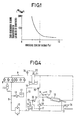
- the amount of the heat medium, as well as the amount of the fuel used in the coke oven is adjusted in accordance with the variation of the moisture content of the coking coal to be charged in the coke oven, and desirably the temperature of the heat medium is controlled at the entrance of the heat exchanger. In this way, as shown in Fig. 3, the moisture content of the coking coal is maintained constantly at about 5%.
- the cooler provided before the heat exchanger in the ascension pipe is operated when the temperature of the heat medium coming out from the coal drier is higher than the predetermined temperature.
- the amount of the fuel used in the heating furnace for heating the heat medium is increased so as to control the temperature of the heat medium entering the heat exchanger in the ascension pipe.
- the temperature of the heat medium entering the heat exchanger can be controlled to a constant temperature by connecting the heat medium heating furnace, the coal drier and the cooler in the circulation system.
- the feature of the present invention lies in that the sensible heat of the coke oven gas is recovered with a heat medium and this heat medium is used as the heat source for drying the coking coal.
- the inner side of the mantle wall of the coke oven may not be coated with a lining and the oven gas is cooled by the heat medium directly through the mantle wall, or the mantle wall may be coated with an appropriate lining.
- the heat medium path is made between the inner and outer mantles of metal, or the path is made by straight or spiral piping arrangement so as to circulate the heat medium therethrough to recover the sensible heat of the coke oven gas and increase the temperature of the heat medium.
- the hot blast generated in the separate system is blown into the drier to bring the coal into direct contact with the hot blast to evaporate the moisture content of the coal.
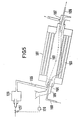
- the heat medium having a high temperature is passed through the pipes so as to perform an indirect heat exchange with the coal 103 moving along the outside of the pipes, thus constantly evaporating a constant amount of the moisture contained in the coal and assuring a moisture content of 7% of the coal.
- the hot blast 105 generated in the hot blast oven 125 is blown into the drier through the front portion 106 or the rear portion 107 so as to bring the coal into direct contact therewith, thus performing the heat exchange, and the waste gas is discharged from the rear portion 107 or the front portion 106.
- the hot blast is maintained at a flow rate and at a temperature just enough to decrease the moisture content of the coal by 2%. It is desirable that the flow rate as well as the temperature of the hot blast can be changed in order to desirably adjust the degree of drying of the coal.
- a moisture meter 120 is provided to measure the moisture content and the signals thereof are sent to the fuel adjusting valve 127 of the host blast generator to control the fuel supply.
- the amount of the fuel used in the hot blast generator in accordance with the variation of the moisture content in the coal and to control the flow rate and temperature of the hot blast at the entrance of the drier, thus maintaining the moisture of the coal coming out of the drier constantly at about 5% as shown in Fig. 3.
- the numerical references 104, 108 and 109 represent respectively a joint, an entrance for the heat medium and an outlet for the heat medium.
- the heat recovery is performed in the ascension pipe portion of the coke oven and at the same time, the heat medium heating furnace, the indirect type coal drier and the cooling means are efficiently and reasonably connected as illustrated in Fig. 4.
- the system for recovering the sensible heat of the coke oven in the ascension pipes comprises a heat exchange means connected to the heat-medium circulation piping 9 at the inlet and the outlet, a heat medium circulation pump 10 in the outlet piping 9, an expansion tank 11, a heat medium storing tank 12 and a supplying pump 13 at appropriate intermediate portion of the piping 9.
- the system for utilizing the sensible heat of the coke oven gas for drying the coking coal comprises a heat medium heating furnace 14 provided at the intermediate of the piping 9 of the heat recovering system, an indirect type coal drier 15 and a cooler 16 arranged after the furnace, a temperature detector 17 at the outlet of the heating furnace 14, a temperature detector 18 at the outlet of the cooler 16, a flow rate adjusting valve 20 at the intermediate of the by-pass pipe 19 of the indirect type coal drier 15, a flow rate adjusting valve 22 at the intermediate of the by-pass pipe 21 of the cooler 16, a moisture meter 24 at the coal supply hopper 23 to the coal drier 15, a coal discharge meter 25, a moisture meter 27 at a reception hopper 26 at the outlet of the drier, a calculator 28 for controlling the moisture content of the coal after the drying to 5%, a gas burner 29 in the heat medium heating furnace, a gas amount adjusting valve 30 and a gas supplying blower 31.
- the heat medium normally flows in the direction shown by an arrow along the solid line in Fig. 4.
- the heat medium heated in the heat exchanger 8 in the ascension pipe is pressurized by the circulation pump 10 to pass through the heat medium heating furnace 14 to enter the coal drier 15 where the heat medium discharges the heat to the coal.
- the amount of heat discharge here is almost equal to the heat of about 50,000 Kcal/ton of coal which the heat medium catches in the heat exchanger, andit is--equivalent to the heat energy required for decreasing the-moisture content of the coal by 4%. Therefore, when the moisture content at the entrance of the drier is 11 %, the moisture content obtained at the outlet of the drier will be 7%.
- the heat medium is heated from 200°C to 220°C in the heating furnace. This can be performed by determining the coal discharge amount by the measure 25, determining the moisture content by the moisture meter 24 and then by the moisture meter 27, processing the signals thus obtained by the calculator to set the temperature of the heat medium at the entrance of the drier, and controlling the combustion gas flow rate by the flow rate valve 31 on the basis of the temperature signal so as to maintain the set temperature of the heat medium in the heating furnace.
- the amount of the heat medium passing through the by-pass pipe 19 is increased while the amount of the heat medium entering the drier is decreased.
- the amount of coal discharge is determined by the discharge meter 25
- the moisture content of the coal is determined by the moisture meter 24 and then by the meter 27, and the detection signals thus obtained are processed by the calculator to control the flow rate of the heat medium passing through the by-pass pipe 19 by the flow rate adjusting valve 20.
- the heat medium is used in a liquid state.
- the boiling point of the heat medium is 280°C, it is desirable to use the medium at about 200°C or lower so as to provide a margin of about 80°C.
- the temperature of the heat medium is set at 160°C at the entrance of the heat exchanger and set at 200°C at the outlet of the pipe. If the moisture content of the coal at the entrance of the coal drier continues to be at 7% or near, the amount of the heat medium passing through the by-pass pipe 19 increases and the temperature of the heat medium at the entrance of the heat exchanger increases to a temperature beyond the boiling point of the heat medium in the course of circulation.
- the cooler 16 is provided to maintain the heat medium at the entrance of the heat exchanger at a constant temperature. This can be done by detecting the temperature at the outlet of the cooler by the detector 18 to control the amount of the flow rate of the heat medium passing through the by-pass pipe 21 to maintain a constant temperature. There is no specific limitation of the cooling method.
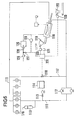
- This Example illustrates the modification of the present invention in which the sensible heat of the coke oven gas is recovered by a heat exchanger in the ascension pipe of the oven and at the same time a hot blast generator is efficiently connected to the indirect type coal drier.
- the sensible heat recovering system in this embodiment is the same as that in the first embodiment.
- the system comprises a heat exchanging means connected to the heat medium circulation piping 111 at the inlet and the outlet, a heat medium circulation pump 112 in the outlet piping 111, an expansion tank 113, a heat medium storing tank 114 and a supplying pump 115 at appropriate intermediate portion of the piping 111.
- the system for utilizing the sensible heat of the coke oven gas in this embodiment comprises a multi-pipe type coal drier 116 provided in the path of the piping 111 of the heat recovering system, a flow rate adjusting valve 118 in the path of the by-pass pipe 117 of the coal drier, a coal supply hopper 119 to the coal drier, a moisture content meter 120, a coal discharge meter 121 provided in the hopper, a reception hopper 122 at the outlet of the drier, a moisture meter 123, a calculator 124 for controlling the moisture content of the coal after the drying to 5%, provided in the reception hopper, a hot blast generator 125, a gas burner 126, a gas amount adjusting valve 127 and a gas supplying blower 128, provided in the hot blast generator 125.
- the heat medium normally flows in the direction shown by the arrow along the solid line as shown in Fig. 6.
- the heat medium heated in the heat exchanger 110 in the ascension pipe is pressurized by the circulation pump 112 and enters the coal drier where it discharges the heat to the coal.
- the heat energy discharged here is almost equal to the heat energy of about 50,000 Kcal/ton of coal which the heat medium recovers in the heat exchanger. This energy is sufficient to decrease the moisture content in the coal by 4%.
- the moisture content at the entrance of the drier is 11%
- the moisture content at the outlet of the drier is 7%.
- a hot blast of 500°C is generated in the hot blast generator and supplied to the drier at a flow rate of 100 Nm 3 /ton of coal.
- the amount of coal discharge is determined by the discharge meter 121 and the moisture content of the coal is determined by the moisture meters 120 and 123 and then their signals are processed by the calculator to set the temperature of the hot blast at the entrance of the drier.
- the temperature signal is received to control the flow rate of the combustion gas by the flow rate adjusting valve 127.
- the amount of heat medium passing through the by-pass pipe 117 is increased while the amount of the heat medium entering the drier is decreased.
- the amount of coal to be discharged is determined by the discharge meter 121
- the moisture content in the coal is determined by the moisture meters 120 and 123 and their signals are processed by the calculator to control the flow rate of the heat medium passing through the by-pass pipe 117 by the flow rate adjusting valve 118.
- the present invention can efficiently recover the sensible heat from the coke oven gas and at the same time can advantageously utilize the recovered heat as a heat source for drying the coking coal to be charged in the coke oven, thus remarkably reducing the amount of fuel consumed in the coke oven and remarkably improving the coke production yield.
- the present invention is very advantageous from the aspect of energy saving.
Landscapes
- Engineering & Computer Science (AREA)
- Chemical & Material Sciences (AREA)
- Mechanical Engineering (AREA)
- General Engineering & Computer Science (AREA)
- Materials Engineering (AREA)
- Oil, Petroleum & Natural Gas (AREA)
- Organic Chemistry (AREA)
- Life Sciences & Earth Sciences (AREA)
- Sustainable Development (AREA)
- Coke Industry (AREA)
- Drying Of Solid Materials (AREA)
Claims (6)
Applications Claiming Priority (4)
| Application Number | Priority Date | Filing Date | Title |
|---|---|---|---|
| JP134220/81 | 1981-08-28 | ||
| JP13422081A JPS5940870B2 (ja) | 1981-08-28 | 1981-08-28 | 石炭乾燥方法 |
| JP134221/81 | 1981-08-28 | ||
| JP13422181A JPS6015673B2 (ja) | 1981-08-28 | 1981-08-28 | 石炭の乾燥方法 |
Publications (3)
| Publication Number | Publication Date |
|---|---|
| EP0073498A2 EP0073498A2 (de) | 1983-03-09 |
| EP0073498A3 EP0073498A3 (en) | 1984-03-28 |
| EP0073498B1 true EP0073498B1 (de) | 1986-11-20 |
Family
ID=26468377
Family Applications (1)
| Application Number | Title | Priority Date | Filing Date |
|---|---|---|---|
| EP82107903A Expired EP0073498B1 (de) | 1981-08-28 | 1982-08-27 | Verfahren zum Trocknen von zu verkokenden Kohlen |
Country Status (5)
| Country | Link |
|---|---|
| US (1) | US4492042A (de) |
| EP (1) | EP0073498B1 (de) |
| KR (1) | KR850001737B1 (de) |
| BR (1) | BR8205044A (de) |
| DE (1) | DE3274366D1 (de) |
Families Citing this family (9)
| Publication number | Priority date | Publication date | Assignee | Title |
|---|---|---|---|---|
| EP0124907A3 (de) * | 1983-05-10 | 1986-06-11 | Nippon Steel Chemical Co., Ltd. | Verfahren zur Trocknung von Kohlen |
| US4750434A (en) * | 1987-09-16 | 1988-06-14 | Shell Oil Company | Mill/dryer gas temperature control |
| KR100502727B1 (ko) * | 1997-07-24 | 2005-12-26 | 엔 바이오 주식회사 | 인삼침출차의제조방법 |
| KR100434437B1 (ko) * | 1998-05-30 | 2004-08-25 | 주식회사 케이티앤지 | 열처리 조건을 이용한 고급 홍삼 수율 증대방법 |
| KR100447609B1 (ko) * | 2002-02-26 | 2004-09-07 | 주식회사 해찬들 | 홍삼고추장 및 그의 제조방법 |
| KR100556503B1 (ko) * | 2002-11-26 | 2006-03-03 | 엘지전자 주식회사 | 건조기의 건조 시간제어 방법 |
| KR100832334B1 (ko) * | 2006-11-13 | 2008-05-26 | 주식회사 케이티앤지 | 페이스트상 연질홍삼의 제조방법 |
| WO2008083703A1 (de) * | 2006-12-28 | 2008-07-17 | Jochen Zingelmann | Verfahren zum trocknen von festen und/oder flüssigen abfallstoffen |
| CN110499168B (zh) * | 2019-09-26 | 2024-06-14 | 葛霖 | 一种串联双元保护荒煤气余热回收换热器上升管 |
Family Cites Families (8)
| Publication number | Priority date | Publication date | Assignee | Title |
|---|---|---|---|---|
| GB207809A (de) * | 1922-11-30 | 1925-04-23 | Kohlenveredlung Gesellschaft Mit Beschraenkter Haftung | |
| DE477915C (de) * | 1928-05-03 | 1929-06-17 | Otto & Co Gmbh Dr C | Vorrichtung zur Ausnutzung der fuehlbaren Waerme der Destillationsgase von OEfen zurErzeugung von Gas und Koks |
| DE1187584B (de) * | 1954-07-30 | 1965-02-25 | Steinmueller Gmbh L & C | Verfahren zur Vortrocknung von Kohle |
| DE2738442B2 (de) * | 1977-08-26 | 1979-10-18 | Didier Engineering Gmbh, 4300 Essen | Verfahren bzw. Anlage zur Nutzung der fühlbaren Kokswärme in einer Verkokungsanlage |
| JPS5923591B2 (ja) * | 1978-05-26 | 1984-06-02 | 日本鋼管株式会社 | コ−クス炉ガスの熱回収方法 |
| US4284476A (en) * | 1978-07-24 | 1981-08-18 | Didier Engineering Gmbh | Process and apparatus for utilization of the sensible heat of hot coke for drying and preheating coking coal |
| FR2462467A1 (fr) * | 1979-07-30 | 1981-02-13 | Charbonnages De France | Procede et installation de sechage et/ou prechauffage de charbon a cokefier |
| DE3107407C2 (de) * | 1980-09-17 | 1985-08-22 | Carl Still Gmbh & Co Kg, 4350 Recklinghausen | Verfahren und Vorrichtung zur indirekten Trocknung und Vorerhitzung von Feingütern |
-
1982
- 1982-08-26 US US06/412,523 patent/US4492042A/en not_active Expired - Lifetime
- 1982-08-27 EP EP82107903A patent/EP0073498B1/de not_active Expired
- 1982-08-27 DE DE8282107903T patent/DE3274366D1/de not_active Expired
- 1982-08-27 BR BR8205044A patent/BR8205044A/pt not_active IP Right Cessation
- 1982-08-28 KR KR8203885A patent/KR850001737B1/ko not_active Expired
Also Published As
| Publication number | Publication date |
|---|---|
| EP0073498A3 (en) | 1984-03-28 |
| DE3274366D1 (en) | 1987-01-08 |
| US4492042A (en) | 1985-01-08 |
| KR850001737B1 (ko) | 1985-12-07 |
| EP0073498A2 (de) | 1983-03-09 |
| KR840001209A (ko) | 1984-03-28 |
| BR8205044A (pt) | 1983-08-09 |
Similar Documents
| Publication | Publication Date | Title |
|---|---|---|
| US4354903A (en) | Process for drying and preheating coal utilizing heat in dry cooling or quenching of coke | |
| JP2017522527A (ja) | 発電設備用高水分、低発熱量褐炭の乾燥及び水分回収方法並びにその装置 | |
| US4492042A (en) | Method for drying coking coals to be charged in a coke oven | |
| CN103575068A (zh) | 褐煤干燥水回收及干燥尾气再循环利用系统 | |
| US4338160A (en) | Process for drying and/or preheating coal | |
| US5326081A (en) | Method and apparatus for cooling hot gases | |
| EP0613542A1 (de) | Verfahren und vorrichtung zum trocknen des brennstoffes eines wirbelbettkessels. | |
| CN105624349A (zh) | 高炉炉渣干法粒化后的余热锅炉 | |
| US4240877A (en) | Method for preheating coal for coking | |
| JPS5837082A (ja) | 石炭乾燥方法 | |
| US2102424A (en) | Mercury power plant | |
| CN110186287B (zh) | 一种高温渣余热利用方法和系统 | |
| RU2034010C1 (ru) | Способ сухого тушения кокса и устройство для его осуществления | |
| JPS60188489A (ja) | コ−クスを乾燥冷却する際ガスによつて発生する顕熱の利用法 | |
| WAKURI et al. | New moisture control system of coal for coking | |
| CN112268466B (zh) | 回收冶金余热的工艺装置及方法 | |
| EP0124907A2 (de) | Verfahren zur Trocknung von Kohlen | |
| JPS5837083A (ja) | 石炭の乾燥方法 | |
| CN106855249A (zh) | 一种防止烟气露点腐蚀的余热回收系统 | |
| CN208818016U (zh) | 电弧炉余热利用系统 | |
| JPH06108058A (ja) | 石炭調湿設備の調湿炭の水分制御方法 | |
| CN220887289U (zh) | 一种污泥热解炭化系统 | |
| JPH10279961A (ja) | タールを含むガスの熱回収方法及び装置 | |
| KR101504425B1 (ko) | 분코크스 재순환 시스템 | |
| JPS62158784A (ja) | コ−クス用原料炭の乾燥方法 |
Legal Events
| Date | Code | Title | Description |
|---|---|---|---|
| PUAI | Public reference made under article 153(3) epc to a published international application that has entered the european phase |
Free format text: ORIGINAL CODE: 0009012 |
|
| AK | Designated contracting states |
Designated state(s): DE GB IT NL |
|
| PUAL | Search report despatched |
Free format text: ORIGINAL CODE: 0009013 |
|
| AK | Designated contracting states |
Designated state(s): DE GB IT NL |
|
| 17P | Request for examination filed |
Effective date: 19840430 |
|
| GRAA | (expected) grant |
Free format text: ORIGINAL CODE: 0009210 |
|
| AK | Designated contracting states |
Kind code of ref document: B1 Designated state(s): DE GB IT NL |
|
| ITF | It: translation for a ep patent filed | ||
| REF | Corresponds to: |
Ref document number: 3274366 Country of ref document: DE Date of ref document: 19870108 |
|
| PLBE | No opposition filed within time limit |
Free format text: ORIGINAL CODE: 0009261 |
|
| STAA | Information on the status of an ep patent application or granted ep patent |
Free format text: STATUS: NO OPPOSITION FILED WITHIN TIME LIMIT |
|
| 26N | No opposition filed | ||
| ITTA | It: last paid annual fee | ||
| PGFP | Annual fee paid to national office [announced via postgrant information from national office to epo] |
Ref country code: GB Payment date: 19970818 Year of fee payment: 16 |
|
| PGFP | Annual fee paid to national office [announced via postgrant information from national office to epo] |
Ref country code: NL Payment date: 19970826 Year of fee payment: 16 |
|
| PG25 | Lapsed in a contracting state [announced via postgrant information from national office to epo] |
Ref country code: GB Free format text: LAPSE BECAUSE OF NON-PAYMENT OF DUE FEES Effective date: 19980827 |
|
| PG25 | Lapsed in a contracting state [announced via postgrant information from national office to epo] |
Ref country code: NL Free format text: LAPSE BECAUSE OF NON-PAYMENT OF DUE FEES Effective date: 19990301 |
|
| GBPC | Gb: european patent ceased through non-payment of renewal fee |
Effective date: 19980827 |
|
| NLV4 | Nl: lapsed or anulled due to non-payment of the annual fee |
Effective date: 19990301 |
|
| PGFP | Annual fee paid to national office [announced via postgrant information from national office to epo] |
Ref country code: DE Payment date: 19990827 Year of fee payment: 18 |
|
| PG25 | Lapsed in a contracting state [announced via postgrant information from national office to epo] |
Ref country code: DE Free format text: LAPSE BECAUSE OF NON-PAYMENT OF DUE FEES Effective date: 20010501 |