EP0073565A1 - Ventileinheit zur Durchflussregelung - Google Patents
Ventileinheit zur Durchflussregelung Download PDFInfo
- Publication number
- EP0073565A1 EP0073565A1 EP82303798A EP82303798A EP0073565A1 EP 0073565 A1 EP0073565 A1 EP 0073565A1 EP 82303798 A EP82303798 A EP 82303798A EP 82303798 A EP82303798 A EP 82303798A EP 0073565 A1 EP0073565 A1 EP 0073565A1
- Authority
- EP
- European Patent Office
- Prior art keywords
- plug
- assembly
- fluid flow
- ring
- plate
- Prior art date
- Legal status (The legal status is an assumption and is not a legal conclusion. Google has not performed a legal analysis and makes no representation as to the accuracy of the status listed.)
- Granted
Links
- 239000012530 fluid Substances 0.000 title claims abstract description 24
- 239000000463 material Substances 0.000 claims description 2
- 239000002184 metal Substances 0.000 claims description 2
- 230000003628 erosive effect Effects 0.000 abstract description 4
- 229910000831 Steel Inorganic materials 0.000 abstract description 3
- 239000010959 steel Substances 0.000 abstract description 3
- 230000000712 assembly Effects 0.000 description 2
- 238000000429 assembly Methods 0.000 description 2
- 230000005540 biological transmission Effects 0.000 description 2
- 238000001125 extrusion Methods 0.000 description 1
- 238000011065 in-situ storage Methods 0.000 description 1
- 230000001681 protective effect Effects 0.000 description 1
- 239000012858 resilient material Substances 0.000 description 1
Images
Classifications
-
- F—MECHANICAL ENGINEERING; LIGHTING; HEATING; WEAPONS; BLASTING
- F16—ENGINEERING ELEMENTS AND UNITS; GENERAL MEASURES FOR PRODUCING AND MAINTAINING EFFECTIVE FUNCTIONING OF MACHINES OR INSTALLATIONS; THERMAL INSULATION IN GENERAL
- F16K—VALVES; TAPS; COCKS; ACTUATING-FLOATS; DEVICES FOR VENTING OR AERATING
- F16K7/00—Diaphragm valves or cut-off apparatus, e.g. with a member deformed, but not moved bodily, to close the passage ; Pinch valves
- F16K7/20—Diaphragm valves or cut-off apparatus, e.g. with a member deformed, but not moved bodily, to close the passage ; Pinch valves with a compressible solid closure member
-
- Y—GENERAL TAGGING OF NEW TECHNOLOGICAL DEVELOPMENTS; GENERAL TAGGING OF CROSS-SECTIONAL TECHNOLOGIES SPANNING OVER SEVERAL SECTIONS OF THE IPC; TECHNICAL SUBJECTS COVERED BY FORMER USPC CROSS-REFERENCE ART COLLECTIONS [XRACs] AND DIGESTS
- Y10—TECHNICAL SUBJECTS COVERED BY FORMER USPC
- Y10T—TECHNICAL SUBJECTS COVERED BY FORMER US CLASSIFICATION
- Y10T137/00—Fluid handling
- Y10T137/3367—Larner-Johnson type valves; i.e., telescoping internal valve in expanded flow line section
Definitions
- the present invention relates to a valve assembly for controlling fluid flow, particularly gas flow, in a fluid flow regulator of the type providing a controlled variation in volume of flow through the fluid transmission pipe line.
- Valve assemblies for the purpose described above usually comprise a deformable plug having a cylindrical body which is situated in a housing providing a passageway for fluid.
- the plug is seated within a valve seat in the housing between two backing plates forming part of the assembly.
- the plug outer diameter is such that when unstressed there is provided between the plug and the valve seat an annular clearance for the flow of fluid.
- one backing plate is fixed to the housing and other plate can be moved towards the fixed plate by some form of axial stressing means, such as a movable cylinder, so that the plug is stressed between the plates and radially expands to restrict the annular clearance and thereby fluid flow.
- the cylinder is hydraulically linked to a diaphragm motor assembly which serves to provide fine adjustment of' the pressure of the hydraulic fluid and thereby of the cylinder movement.
- a typical conventional valve assembly and fluid flow regulator is described in some detail in UK Patent Specification No. 1035427.
- valve assembly for controlling fluid flow in a fluid flow regulator, the assembly including a deformable plug having a cylindrical body which is circumferentially grooved.
- the plug is formed with a wear resistant surface extending inwardly from one end.
- the surface is formed by a ring of a wear resistant material secured to the plug body.
- the ring is of metal.
- the plug is provided at each end with a backing plate.
- one end of the plug is provided with a projecting circular neck portion which is located between the ring and the corresponding backing plate.
- the plug has only one circumferential groove which is located closer to one end of the plug than to the other.
- the plug has only one circumferential groove which is located closer to that end adjacent the wear resistant surface than to the other end.
- the plug ends and the backing plates have surfaces conforming to each other.
- one of the plug end surfaces forms a recess to retain an insert portion on one of the backing plates.
- the recess is located at one end of the plug and the wear resistant surface is at the opposite end of the plug.
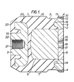
- valve assembly shown in Figure 1 comprises a plug 1 of a deformable yet resilient material such as rubber, a pair of steel backing plates 2 and 3 located at either end of the plug 1 and a flanged steel ring 4 disposed at the same end of the plug 1 as the backing plate 2.
- the plug 1 has a cylindrical body which is provided with a circumferential groove 5 adjacent to the ring 4.
- the groove 5 extends for approximately one fifth of the plug length and to a depth of about one tenth of the plug radius.
- the plug 1 comprises two portions, an inner core 6 and an outer sleeve 7 enclosing the core 6.
- the inner core 6 is of a rubber which is softer and more resilient than the outer sleeve 7 to enable the plug to deform radially outwardly more easily.
- the backing plate 2 is also formed in two portions, a central disc 8 seated within an outer annulus 9.
- the disc 8 is secured by fixing screws (not shown) to the annulus 9.
- the plug sleeve 7 has a circular neck portion 10 formed at one end and this is located between the ring 4 and the backing plate 2, the ring being a push fit onto the neck 10.
- the ring 4 itself has an axial portion 11 whose outer surface is substantially parallel to the outer axial surface 12 of the plug sleeve 7, and an annular end portion 13 engaged in a recess in the annular portion 9 of the backing plate 2.
- This annular portion 9 has an inwardly directed circular rib 14 which is located within a corresponding circular recess in the adjacent end of the plug body and is bonded to the plug 1.
- the plate disc 8 has a circular central bore 15 formed with splines 16 extending partially inwardly from the outer face of the plate 2.
- a circular bush 17 having a partially externally splined surface corresponding to the splines 16 is located and held within the bore 15.
- the bush 17 has a hexagonal internal bore 18 for engaging a cylindrical spigot extending from an actuating cylinder shown in Figure 2 as will be subsequently described.
- the plug 1 is formed at its other end with a seat or recess to receive the backing plate 3.
- the backing plate 3 has a cylindrical neck portion 19 extending through a corresponding bore in the end of the plug and terminating in a cap.20 located in a corresponding recess in the plug sleeve 7 and bonded thereto so as to hold the plate 3 securely in engagement with the plug 1.
- the cylindrical portion 19 of the plate 3 is formed with a threaded internal bore 21 to receive a mounting screw as will be subsequently described.
- the outer face 22 of the backing plate 3 terminates flush with the outer surface 23 of the plug end adjacent the plate 3.
- the plates 2 and 3 and the ring 4 can be formed in situ with the plug 1 when moulded.
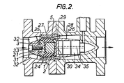
- valve assembly 24 is located in a cylindrical valve seat 25 of a conventional fluid flow regulator formed in a fluid transmission pipe line 26.
- the plug outer diameter is such that when unstressed there is provided between the plug and the valve seat an annular clearance 27 for the flow of fluid (flowing in the direction of the arrows.)
- a movable cylinder 28 engages the backing plate 2 to move the plate 2 towards the backing plate 3 to stress the plug 1 and restrict the annular clearance 27.
- the front wall 29 of the cylinder 28 is provided with a projecting cylindrical spigot 30 which locates in the hexagonal bore 18 of the bush 17 to guide the plate 2 during its movement.
- the backing plate 3 is secured to a fixed boss 31 which itself is secured by fins 32 to the internal wall of the pipe line.
- the boss 31 is provided with a threaded central bore corresponding to the threaded internal bore 21 of the backing plate 3 and with a counter-sunk recess so as to receive a counter-sunk mounting screw 33 to attach the backing plate 3 to the boss 31.
- the cylinder 28 moves relative to a fixed internal piston 34 which is suitably secured by means (not shown) to the internal wall of the pipe line 25.
- the piston 34 is provided internally with a passageway 35 terminating at one end adjacent the cylinder front wall 29 and communicating with a diaphragm motor assembly (not shown) for supplying hydraulic fluid into the passageway 35.
- the pressure exerted by the fluid upon the front wall 29 of the cylinder 28 causes it to move and thereby move the movable backing plate 2 towards the fixed backing plate 3.
- the plug 1 is stressed between the plates 2 and 3 and radially expands to restrict the annular clearance 27 and thereby fluid flow.
- the pressure of the hydraulic fluid can be accurately controlled by the motor thus enabling the movement of the cylinder 28 and consequently the expansion of the plug 1 to be finely adjusted. Relaxation of the hydraulic pressure causes the plug 1 to return to its original unstressed shape thereby retracting the backing plate 2 and the cylinder 28.
- the presence of the groove 5 in the plug 1 adjacent to the movable backing plate 2 surprisingly serves to significantly increase the overall lifetime of the plug 1 compared with the service life of conventional ungrooved plugs 1. This is believed to be due to the fact that the groove removes the point of maximum stress concentration within the plug and thereby prevents the extrusion of the rubber at the movable end of the plug. Consequently the erosion of the plug caused by the flow of gas during the period when the plug is stressed is eliminated.
- the ring 4 forms a protective shroud for the movable end surface of the plug and prevents or inhibits the erosion which occurs with conventional plugs where the surface is in direct contact with the gas.
- the plate 2 can be made in a two part section when a two part plug is being made or as an integral component when a one part plug is being made.
Landscapes
- Engineering & Computer Science (AREA)
- General Engineering & Computer Science (AREA)
- Mechanical Engineering (AREA)
- Lift Valve (AREA)
- Sliding Valves (AREA)
- Magnetically Actuated Valves (AREA)
- Valve Housings (AREA)
- Fluid-Driven Valves (AREA)
Priority Applications (1)
| Application Number | Priority Date | Filing Date | Title |
|---|---|---|---|
| AT82303798T ATE17272T1 (de) | 1981-08-27 | 1982-07-20 | Ventileinheit zur durchflussregelung. |
Applications Claiming Priority (2)
| Application Number | Priority Date | Filing Date | Title |
|---|---|---|---|
| GB8126096 | 1981-08-27 | ||
| GB08126096A GB2105003B (en) | 1981-08-27 | 1981-08-27 | Valve assembly |
Publications (2)
| Publication Number | Publication Date |
|---|---|
| EP0073565A1 true EP0073565A1 (de) | 1983-03-09 |
| EP0073565B1 EP0073565B1 (de) | 1986-01-02 |
Family
ID=10524188
Family Applications (1)
| Application Number | Title | Priority Date | Filing Date |
|---|---|---|---|
| EP82303798A Expired EP0073565B1 (de) | 1981-08-27 | 1982-07-20 | Ventileinheit zur Durchflussregelung |
Country Status (5)
| Country | Link |
|---|---|
| US (1) | US4799647A (de) |
| EP (1) | EP0073565B1 (de) |
| AT (1) | ATE17272T1 (de) |
| DE (1) | DE3268268D1 (de) |
| GB (1) | GB2105003B (de) |
Cited By (2)
| Publication number | Priority date | Publication date | Assignee | Title |
|---|---|---|---|---|
| EP0683233A2 (de) | 1994-05-18 | 1995-11-22 | The Green Cross Corporation | Verfahren zur Herstellung von rekombinantem menschlichen Serumalbumin |
| WO2012030708A3 (en) * | 2010-08-31 | 2012-06-07 | Borgwarner Inc. | Electronic coolant valve with flexible seal |
Families Citing this family (3)
| Publication number | Priority date | Publication date | Assignee | Title |
|---|---|---|---|---|
| US6068011A (en) | 1993-10-13 | 2000-05-30 | Paradis; Joseph R. | Control of fluid flow |
| FR2778760B1 (fr) * | 1998-05-15 | 2000-06-23 | Cahouet | Regulateur de pression d'un fluide |
| US7775233B2 (en) * | 2007-03-15 | 2010-08-17 | Baker Hughes Incorporated | Choke or inline valve |
Citations (5)
| Publication number | Priority date | Publication date | Assignee | Title |
|---|---|---|---|---|
| GB644039A (en) * | 1946-11-30 | 1950-10-04 | Thomas Nicholas Young | Improvements relating to stop valves or control valves |
| US3095904A (en) * | 1960-12-27 | 1963-07-02 | Thaning Niels Otto | Valves for the control of fluid flow |
| GB1035427A (en) * | 1964-08-26 | 1966-07-06 | Texsteam Corp | Fluid flow regulator |
| DE2221732B2 (de) * | 1971-05-05 | 1975-10-30 | Texsteam Corp., Houston, Tex. (V.St.A.) | Ventil zur Regelung der Strömungsmittelmenge |
| DE1550563B2 (de) * | 1965-11-30 | 1976-07-22 | Texsteam Corp., Chicago, 111· (V.St.A.) | Steuerventil mit einem massiven dichtglied aus einem elastomer |
Family Cites Families (9)
| Publication number | Priority date | Publication date | Assignee | Title |
|---|---|---|---|---|
| US2917269A (en) * | 1958-06-20 | 1959-12-15 | Robert H Welker | Flow regulator |
| US2992808A (en) * | 1958-10-06 | 1961-07-18 | Oscar C Rixson Co | Metering valve |
| NL154583B (nl) * | 1964-08-26 | 1977-09-15 | Texsteam Corp | Regelafsluiter. |
| US3836113A (en) * | 1969-10-17 | 1974-09-17 | Singer Co | Axial flow valve |
| US4137933A (en) * | 1977-02-14 | 1979-02-06 | Trw Inc. | Control valve |
| US4206902A (en) * | 1977-06-13 | 1980-06-10 | Vapor Corporation | Inner element for a flow regulator |
| US4188013A (en) * | 1977-08-08 | 1980-02-12 | Honeywell Inc. | Gas valve seating member |
| US4351510A (en) * | 1980-11-10 | 1982-09-28 | Welker Robert H | Flow regulator assembly |
| US4354661A (en) * | 1980-11-10 | 1982-10-19 | Welker Robert H | Constant velocity diffuser |
-
1981
- 1981-08-27 GB GB08126096A patent/GB2105003B/en not_active Expired
-
1982
- 1982-07-20 AT AT82303798T patent/ATE17272T1/de active
- 1982-07-20 DE DE8282303798T patent/DE3268268D1/de not_active Expired
- 1982-07-20 EP EP82303798A patent/EP0073565B1/de not_active Expired
- 1982-07-26 US US06/402,036 patent/US4799647A/en not_active Expired - Lifetime
Patent Citations (5)
| Publication number | Priority date | Publication date | Assignee | Title |
|---|---|---|---|---|
| GB644039A (en) * | 1946-11-30 | 1950-10-04 | Thomas Nicholas Young | Improvements relating to stop valves or control valves |
| US3095904A (en) * | 1960-12-27 | 1963-07-02 | Thaning Niels Otto | Valves for the control of fluid flow |
| GB1035427A (en) * | 1964-08-26 | 1966-07-06 | Texsteam Corp | Fluid flow regulator |
| DE1550563B2 (de) * | 1965-11-30 | 1976-07-22 | Texsteam Corp., Chicago, 111· (V.St.A.) | Steuerventil mit einem massiven dichtglied aus einem elastomer |
| DE2221732B2 (de) * | 1971-05-05 | 1975-10-30 | Texsteam Corp., Houston, Tex. (V.St.A.) | Ventil zur Regelung der Strömungsmittelmenge |
Cited By (2)
| Publication number | Priority date | Publication date | Assignee | Title |
|---|---|---|---|---|
| EP0683233A2 (de) | 1994-05-18 | 1995-11-22 | The Green Cross Corporation | Verfahren zur Herstellung von rekombinantem menschlichen Serumalbumin |
| WO2012030708A3 (en) * | 2010-08-31 | 2012-06-07 | Borgwarner Inc. | Electronic coolant valve with flexible seal |
Also Published As
| Publication number | Publication date |
|---|---|
| DE3268268D1 (en) | 1986-02-13 |
| ATE17272T1 (de) | 1986-01-15 |
| EP0073565B1 (de) | 1986-01-02 |
| US4799647A (en) | 1989-01-24 |
| GB2105003B (en) | 1983-10-12 |
| GB2105003A (en) | 1983-03-16 |
Similar Documents
| Publication | Publication Date | Title |
|---|---|---|
| US2349170A (en) | Sealing device | |
| CN109323006B (zh) | 电子膨胀阀 | |
| US4426086A (en) | Annular seal and method of use | |
| US6776419B2 (en) | Seal for a reciprocating plunger | |
| US4787642A (en) | X-shaped high pressure sealing structure | |
| JPS60227062A (ja) | 高圧パツキン | |
| JPH083349B2 (ja) | シール装置 | |
| US4867460A (en) | Hydraulic jack seal assembly | |
| JPS59226764A (ja) | 深井戸穿孔工具に関する長さ方向移動部材のための高圧シ−ル方法 | |
| US6016892A (en) | Pinless internal automatic adjuster for brake piston | |
| GB2327740A (en) | Valve seal mechanism | |
| US4793451A (en) | Energy absorber device with plastic casing and screw-in plastic seal | |
| US4799647A (en) | Valve assembly for controlling fluid flow | |
| US4671169A (en) | Fluid actuated ram assembly | |
| US3034482A (en) | Adjustable piston cushion | |
| US2917269A (en) | Flow regulator | |
| US2824945A (en) | Plug for core holes or the like | |
| US2687015A (en) | Boot for master cylinders | |
| US2997138A (en) | Wear compensating brake | |
| US4978102A (en) | Aligning and seal ring retracting apparatus for plug type valve | |
| US4222463A (en) | Mechanically actuated brake piston with elastomeric bushing | |
| US2770441A (en) | Fluid pressure regulator | |
| US6820729B2 (en) | Shock absorber cylinder head wiper | |
| DE3564996D1 (en) | Safety valve | |
| US4593713A (en) | Measurement coupling |
Legal Events
| Date | Code | Title | Description |
|---|---|---|---|
| PUAI | Public reference made under article 153(3) epc to a published international application that has entered the european phase |
Free format text: ORIGINAL CODE: 0009012 |
|
| AK | Designated contracting states |
Designated state(s): AT BE CH DE FR IT LI NL |
|
| 17P | Request for examination filed |
Effective date: 19830204 |
|
| ITF | It: translation for a ep patent filed | ||
| GRAA | (expected) grant |
Free format text: ORIGINAL CODE: 0009210 |
|
| RAP1 | Party data changed (applicant data changed or rights of an application transferred) |
Owner name: MORGAN, CLIVE ALEXANDER Owner name: BRITISH GAS CORPORATION |
|
| RIN1 | Information on inventor provided before grant (corrected) |
Inventor name: CRAIGEN, JOSEPH GORDON Inventor name: COOK, TIMOTHY Inventor name: MORGAN, CLIVE ALEXANDER |
|
| AK | Designated contracting states |
Designated state(s): AT BE CH DE FR IT LI NL |
|
| REF | Corresponds to: |
Ref document number: 17272 Country of ref document: AT Date of ref document: 19860115 Kind code of ref document: T |
|
| ET | Fr: translation filed | ||
| REF | Corresponds to: |
Ref document number: 3268268 Country of ref document: DE Date of ref document: 19860213 |
|
| PLBE | No opposition filed within time limit |
Free format text: ORIGINAL CODE: 0009261 |
|
| STAA | Information on the status of an ep patent application or granted ep patent |
Free format text: STATUS: NO OPPOSITION FILED WITHIN TIME LIMIT |
|
| 26N | No opposition filed | ||
| BECH | Be: change of holder |
Free format text: 860102 *BRITISH GAZ P.L.C. |
|
| NLS | Nl: assignments of ep-patents |
Owner name: BRITISH GAS PLC TE LONDEN EN CLIVE ALEXANDER MORGA |
|
| REG | Reference to a national code |
Ref country code: FR Ref legal event code: TP |
|
| ITTA | It: last paid annual fee | ||
| REG | Reference to a national code |
Ref country code: CH Ref legal event code: PFA Free format text: BRITISH GAS CORPORATION;CLIVE ALEXANDER MORGAN TRANSFER- CLIVE ALEXANDER MORGAN;BG PLC |
|
| PGFP | Annual fee paid to national office [announced via postgrant information from national office to epo] |
Ref country code: AT Payment date: 20010608 Year of fee payment: 20 |
|
| PGFP | Annual fee paid to national office [announced via postgrant information from national office to epo] |
Ref country code: FR Payment date: 20010611 Year of fee payment: 20 |
|
| PGFP | Annual fee paid to national office [announced via postgrant information from national office to epo] |
Ref country code: CH Payment date: 20010618 Year of fee payment: 20 |
|
| PGFP | Annual fee paid to national office [announced via postgrant information from national office to epo] |
Ref country code: NL Payment date: 20010619 Year of fee payment: 20 |
|
| PGFP | Annual fee paid to national office [announced via postgrant information from national office to epo] |
Ref country code: DE Payment date: 20010625 Year of fee payment: 20 |
|
| PGFP | Annual fee paid to national office [announced via postgrant information from national office to epo] |
Ref country code: BE Payment date: 20010713 Year of fee payment: 20 |
|
| BE20 | Be: patent expired |
Free format text: 20020720 *BG PUBLIC LIMITED COMPANY |
|
| PG25 | Lapsed in a contracting state [announced via postgrant information from national office to epo] |
Ref country code: LI Free format text: LAPSE BECAUSE OF EXPIRATION OF PROTECTION Effective date: 20020719 Ref country code: CH Free format text: LAPSE BECAUSE OF EXPIRATION OF PROTECTION Effective date: 20020719 |
|
| PG25 | Lapsed in a contracting state [announced via postgrant information from national office to epo] |
Ref country code: NL Free format text: LAPSE BECAUSE OF EXPIRATION OF PROTECTION Effective date: 20020720 Ref country code: AT Free format text: LAPSE BECAUSE OF EXPIRATION OF PROTECTION Effective date: 20020720 |
|
| REG | Reference to a national code |
Ref country code: CH Ref legal event code: PL |
|
| NLV7 | Nl: ceased due to reaching the maximum lifetime of a patent |
Effective date: 20020720 |