EP0073586A1 - Plateau mené d'embrayage à friction - Google Patents
Plateau mené d'embrayage à friction Download PDFInfo
- Publication number
- EP0073586A1 EP0073586A1 EP82304237A EP82304237A EP0073586A1 EP 0073586 A1 EP0073586 A1 EP 0073586A1 EP 82304237 A EP82304237 A EP 82304237A EP 82304237 A EP82304237 A EP 82304237A EP 0073586 A1 EP0073586 A1 EP 0073586A1
- Authority
- EP
- European Patent Office
- Prior art keywords
- leaf spring
- driven plate
- resilient
- rotation
- resilient means
- Prior art date
- Legal status (The legal status is an assumption and is not a legal conclusion. Google has not performed a legal analysis and makes no representation as to the accuracy of the status listed.)
- Withdrawn
Links
- 230000002093 peripheral effect Effects 0.000 claims description 2
- 230000006835 compression Effects 0.000 claims 2
- 238000007906 compression Methods 0.000 claims 2
- 230000003247 decreasing effect Effects 0.000 claims 1
- 230000001419 dependent effect Effects 0.000 claims 1
- 230000000063 preceeding effect Effects 0.000 claims 1
- 238000013016 damping Methods 0.000 description 7
- 229920001971 elastomer Polymers 0.000 description 6
- OKTJSMMVPCPJKN-UHFFFAOYSA-N Carbon Chemical compound [C] OKTJSMMVPCPJKN-UHFFFAOYSA-N 0.000 description 2
- 229910052799 carbon Inorganic materials 0.000 description 2
- 238000010276 construction Methods 0.000 description 2
- 239000000835 fiber Substances 0.000 description 2
- 229910000639 Spring steel Inorganic materials 0.000 description 1
- 239000000853 adhesive Substances 0.000 description 1
- 230000001070 adhesive effect Effects 0.000 description 1
- 238000006073 displacement reaction Methods 0.000 description 1
- 239000000806 elastomer Substances 0.000 description 1
- 230000010355 oscillation Effects 0.000 description 1
Images


Classifications
-
- F—MECHANICAL ENGINEERING; LIGHTING; HEATING; WEAPONS; BLASTING
- F16—ENGINEERING ELEMENTS AND UNITS; GENERAL MEASURES FOR PRODUCING AND MAINTAINING EFFECTIVE FUNCTIONING OF MACHINES OR INSTALLATIONS; THERMAL INSULATION IN GENERAL
- F16D—COUPLINGS FOR TRANSMITTING ROTATION; CLUTCHES; BRAKES
- F16D13/00—Friction clutches
- F16D13/58—Details
- F16D13/60—Clutching elements
- F16D13/64—Clutch-plates; Clutch-lamellae
- F16D13/68—Attachments of plates or lamellae to their supports
Definitions
- This invention relates to friction clutch driven plates, for but not exclusively for, use on motor vehicle friction clutches.
- a typical friction clutch driven plate comprises an annular friction facing carrier member capable of relative angular rotation about a hub member, said rotation being opposed by resilient means acting between the members.
- Such a driven plate will hereinafter be called a driven plate of the kind referred.
- a driven plate of the kind referred is described in British Patent 473 596 in which the relative rotation is resisted by V-shaped leaf springs each having a rubber block disposed within the 'V'.
- a driven plate as shown in British Patent 473 596 is unsuitable for damping out idle rattle because it cannot provide for different resilient means to come into operation during different sectors of rotation of the facing carrier about the hub.
- the resilient member acting radially against the leaf spring is an elastomeric . block located adjacent the leaf spring, and at a mid length point along the leaf spring.
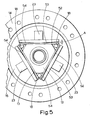
- a friction clutch driven plate for an automobile has a hub member 11 with a circumferential flange 12 thereon.
- the outer peripheral edge 13 of the flange 12 is shaped in a cam form which in this case is substantially triangular.
- a pair of opposed annular friction facings 14 are co-axially mounted on a friction facing carrier member 15 which comprises an annular facing carrier plate 16 located on one side of the flange 12, and an annular retainer plate 17 located on the other side of the flange 12 and secured to the carrier plate 16 by three equiangularly spaced rivets 18.
- the friction facing carrier member 15 can rotate about the hub member 11, this rotation being opposed by three resilient means 21.
- the resilient means 21 are located adjacent each face of the triangular flange 12 and each comprises a leaf spring 22 arranged on a chord of annular plates 16 and 17, and an elastomeric block 23 adjacent the radially outer face of the spring 22, and at its approximate mid-length.
- Each leaf spring 22 comprises four spring steel leaves 26 which decrease step-wise in length radially outwardly, and each spring is housed between the plates 16 and 17 so that it is free to move therebetween.
- the mid-portion of each leaf spring has axially projecting lugs 24 thereon (see Fig. 3) that are accommodated in radial slots 25 in the plates 16 and 17 so as to locate the respective spring.
- Each slot 25 allows the respective spring 22 to move radially.
- Each elastomeric block 23 is fixed to a backing plate 26 by adhesive, and the backing plate is located in slots in the side plates 16 and 17.
- Each block 23 acts radially against the leaf spring to bias its respective spring radially inwardly in the slot 25, the radial inward movement being limited by abutment against two of the rivets 18 which are located one at each end of a leaf spring.
- the driven plate operates in the following manner with the hub member held stationary and the friction facing rotated in an anti-clockwise direction (arrow A) so that the plate is operating in its drive mode.
- Each leaf spring 52 is a carbon fibre resilient beam backed up by a stiff support lever 53 and each lever 53 then reacts back onto the elastomeric block 23.
- the face 54 of the lever 53 adjacent the resilient beam 52 is inclined to taper away from the beam so that there is a clearance 'A' between the end portions of the beam and the support lever.
- This construction has several advantages in that as the carrier 16 rotates the contact point between the hub flange 12 and the beam 52 moves towards the centre of the beam increasing its effective stiffness before the elastomeric block 23 comes into operation.
- the shape of the beam 52 can be varied to give the required torque versus deflection characteristics for the driven plate, and the angle of inclination on the backing lever 53 can also be altered so that the clearance 'A' can be varied as required. Indeed the three support levers 53 could have different clearances so that the elastomeric blocks 25 come into operation at different times.
- triangle faces of the flange can be shaped to give the form of load/deflection curve desired, and to this end the rubber block need not necessarily be in the mid length position but may be offset so that the drive and overdrive curves are different.
- the rubber block 23 could be replaced by a radially aligned coil spring.
- each leaf spring can each be limited by pins 28 so that further movement of the carrier member 15 about the hub member 11 causes the end portions of each leaf spring to be held in position and the central portion of the spring to distort. This obviously will change the operational characteristics of a given leaf spring from when the ends are free.
Landscapes
- Engineering & Computer Science (AREA)
- General Engineering & Computer Science (AREA)
- Mechanical Engineering (AREA)
- Mechanical Operated Clutches (AREA)
Applications Claiming Priority (2)
| Application Number | Priority Date | Filing Date | Title |
|---|---|---|---|
| GB8126428 | 1981-08-29 | ||
| GB8126428 | 1981-08-29 |
Publications (1)
| Publication Number | Publication Date |
|---|---|
| EP0073586A1 true EP0073586A1 (fr) | 1983-03-09 |
Family
ID=10524246
Family Applications (1)
| Application Number | Title | Priority Date | Filing Date |
|---|---|---|---|
| EP82304237A Withdrawn EP0073586A1 (fr) | 1981-08-29 | 1982-08-11 | Plateau mené d'embrayage à friction |
Country Status (2)
| Country | Link |
|---|---|
| EP (1) | EP0073586A1 (fr) |
| ZA (1) | ZA825773B (fr) |
Cited By (2)
| Publication number | Priority date | Publication date | Assignee | Title |
|---|---|---|---|---|
| FR2555268A1 (fr) * | 1983-11-18 | 1985-05-24 | Daikin Mfg Co Ltd | Disque d'embrayage, notamment pour embrayage a disque fonctionnant a sec |
| DE3343190A1 (de) * | 1983-11-29 | 1985-06-05 | Kabushiki Kaisha Daikin Seisakusho, Neyagawa, Osaka | Kupplungsscheibe einer trockenkupplung |
Citations (8)
| Publication number | Priority date | Publication date | Assignee | Title |
|---|---|---|---|---|
| US1704503A (en) * | 1927-11-30 | 1929-03-05 | Borg & Beck Co | Clutch plate |
| US1946144A (en) * | 1932-05-18 | 1934-02-06 | Perfection Gcar Co | Flexible damper clutch plate assembly |
| US1959213A (en) * | 1932-12-02 | 1934-05-15 | Charles I Nygard | Clutch plate |
| US1963187A (en) * | 1931-10-23 | 1934-06-19 | Clarence G Wood | Clutch plate |
| GB473596A (en) * | 1936-03-16 | 1937-10-18 | George Enoch Stanley | Torsional shock-absorbers |
| FR883729A (fr) * | 1941-07-23 | 1943-07-13 | Daimler Benz Ag | Procédé servant à limiter les oscillations de résonance, en particulier dans un système à masses multiples, par exemple sur le vilebrequin de moteurs à combustion interne |
| GB714644A (en) * | 1952-05-12 | 1954-09-01 | Laycock Eng Ltd | Improvements in or relating to torque damping devices |
| US2724252A (en) * | 1952-05-08 | 1955-11-22 | Mack Mfg Corp | Clutch vibration dampener |
-
1982
- 1982-08-10 ZA ZA825773A patent/ZA825773B/xx unknown
- 1982-08-11 EP EP82304237A patent/EP0073586A1/fr not_active Withdrawn
Patent Citations (8)
| Publication number | Priority date | Publication date | Assignee | Title |
|---|---|---|---|---|
| US1704503A (en) * | 1927-11-30 | 1929-03-05 | Borg & Beck Co | Clutch plate |
| US1963187A (en) * | 1931-10-23 | 1934-06-19 | Clarence G Wood | Clutch plate |
| US1946144A (en) * | 1932-05-18 | 1934-02-06 | Perfection Gcar Co | Flexible damper clutch plate assembly |
| US1959213A (en) * | 1932-12-02 | 1934-05-15 | Charles I Nygard | Clutch plate |
| GB473596A (en) * | 1936-03-16 | 1937-10-18 | George Enoch Stanley | Torsional shock-absorbers |
| FR883729A (fr) * | 1941-07-23 | 1943-07-13 | Daimler Benz Ag | Procédé servant à limiter les oscillations de résonance, en particulier dans un système à masses multiples, par exemple sur le vilebrequin de moteurs à combustion interne |
| US2724252A (en) * | 1952-05-08 | 1955-11-22 | Mack Mfg Corp | Clutch vibration dampener |
| GB714644A (en) * | 1952-05-12 | 1954-09-01 | Laycock Eng Ltd | Improvements in or relating to torque damping devices |
Cited By (2)
| Publication number | Priority date | Publication date | Assignee | Title |
|---|---|---|---|---|
| FR2555268A1 (fr) * | 1983-11-18 | 1985-05-24 | Daikin Mfg Co Ltd | Disque d'embrayage, notamment pour embrayage a disque fonctionnant a sec |
| DE3343190A1 (de) * | 1983-11-29 | 1985-06-05 | Kabushiki Kaisha Daikin Seisakusho, Neyagawa, Osaka | Kupplungsscheibe einer trockenkupplung |
Also Published As
| Publication number | Publication date |
|---|---|
| ZA825773B (en) | 1983-06-29 |
Similar Documents
| Publication | Publication Date | Title |
|---|---|---|
| US4222476A (en) | Torsion damping device for friction plate having a flexible center | |
| US4493674A (en) | Vibration damper assembly | |
| US5725080A (en) | Clutch for motor vehicles having a clutch disc with spring elements connected in series | |
| KR950013930B1 (ko) | 자동차용 디스크형 마찰 클러치의 비틀림 감쇄 장치 | |
| US5205788A (en) | Torsional shock absorber with consecutive step-wise elastic resistance to relative rotation | |
| US5249660A (en) | Clutch disc for a motor vehicle friction clutch | |
| US5065642A (en) | Apparatus for absorbing torque variation | |
| EP0259173B1 (fr) | Volant d'inertie avec amortisseur de torsion | |
| US5823516A (en) | Torsion damping device having metallic seats for its springs, especially for a motor vehicle | |
| EP0286213A1 (fr) | Dispositif amortisseur de torsion | |
| GB2060819A (en) | Mounting clutch discs | |
| EP0510038B1 (fr) | Plateaux d'appui d'embrayage a friction | |
| GB2042680A (en) | Clutch disc assemblies | |
| KR100545416B1 (ko) | 토션댐퍼 | |
| US5014842A (en) | Torsion damping device for an automotive friction clutch disc | |
| EP0696694A1 (fr) | Disque absorbeur de couple de rotation | |
| KR100516572B1 (ko) | 토션댐퍼 | |
| US4789374A (en) | Torsional vibration absorber | |
| AU6121780A (en) | Two-stage coaxial spring damper | |
| KR20060130145A (ko) | 이중질량체 클러치플라이휠 및 이중질량체클러치플라이휠을 생산하기 위한 방법 | |
| US6332843B1 (en) | Damper disk assembly | |
| US6488139B1 (en) | Damper mechanism | |
| US4538718A (en) | Clutch disc arrangement | |
| US5141474A (en) | Damper disc | |
| GB2111642A (en) | Clutch disk |
Legal Events
| Date | Code | Title | Description |
|---|---|---|---|
| PUAI | Public reference made under article 153(3) epc to a published international application that has entered the european phase |
Free format text: ORIGINAL CODE: 0009012 |
|
| AK | Designated contracting states |
Designated state(s): BE DE FR GB IT SE |
|
| 17P | Request for examination filed |
Effective date: 19830506 |
|
| STAA | Information on the status of an ep patent application or granted ep patent |
Free format text: STATUS: THE APPLICATION IS DEEMED TO BE WITHDRAWN |
|
| 18D | Application deemed to be withdrawn |
Effective date: 19850518 |
|
| RIN1 | Information on inventor provided before grant (corrected) |
Inventor name: DAVIES, DAVID AUBREY |