EP0073601A1 - Eléments de drainage - Google Patents
Eléments de drainage Download PDFInfo
- Publication number
- EP0073601A1 EP0073601A1 EP82304348A EP82304348A EP0073601A1 EP 0073601 A1 EP0073601 A1 EP 0073601A1 EP 82304348 A EP82304348 A EP 82304348A EP 82304348 A EP82304348 A EP 82304348A EP 0073601 A1 EP0073601 A1 EP 0073601A1
- Authority
- EP
- European Patent Office
- Prior art keywords
- insert
- slot
- drainage
- walls
- drainage channel
- Prior art date
- Legal status (The legal status is an assumption and is not a legal conclusion. Google has not performed a legal analysis and makes no representation as to the accuracy of the status listed.)
- Granted
Links
- 239000000463 material Substances 0.000 claims description 6
- 239000002184 metal Substances 0.000 abstract description 3
- 238000004519 manufacturing process Methods 0.000 description 4
- 238000000034 method Methods 0.000 description 2
- 229910001220 stainless steel Inorganic materials 0.000 description 2
- 239000010935 stainless steel Substances 0.000 description 2
- 238000009825 accumulation Methods 0.000 description 1
- 239000000853 adhesive Substances 0.000 description 1
- 230000001070 adhesive effect Effects 0.000 description 1
- 238000004140 cleaning Methods 0.000 description 1
- 230000000295 complement effect Effects 0.000 description 1
- 238000001035 drying Methods 0.000 description 1
- 238000012986 modification Methods 0.000 description 1
- 230000004048 modification Effects 0.000 description 1
- 238000003825 pressing Methods 0.000 description 1
- 239000003566 sealing material Substances 0.000 description 1
- 238000003466 welding Methods 0.000 description 1
Images

Classifications
-
- E—FIXED CONSTRUCTIONS
- E01—CONSTRUCTION OF ROADS, RAILWAYS, OR BRIDGES
- E01C—CONSTRUCTION OF, OR SURFACES FOR, ROADS, SPORTS GROUNDS, OR THE LIKE; MACHINES OR AUXILIARY TOOLS FOR CONSTRUCTION OR REPAIR
- E01C11/00—Details of pavings
- E01C11/22—Gutters; Kerbs ; Surface drainage of streets, roads or like traffic areas
- E01C11/224—Surface drainage of streets
- E01C11/227—Gutters; Channels ; Roof drainage discharge ducts set in sidewalks
-
- E—FIXED CONSTRUCTIONS
- E02—HYDRAULIC ENGINEERING; FOUNDATIONS; SOIL SHIFTING
- E02B—HYDRAULIC ENGINEERING
- E02B11/00—Drainage of soil, e.g. for agricultural purposes
- E02B11/005—Drainage conduits
Definitions
- This invention is concerned with improvements in or relating to the manufacture of concrete or similar products and is particularly related to the manufacture of drainage blocks.
- a conventional form of drainage block has a substantially rectangular cross-section with the channel extending longitudinally therethrough, the channel being open onto an upper face of the block through aligned slots extending longitudinally of the block.
- Such slots are susceptible to the accumulation of dirt etc., and to prevent clogging it is important to periodically clear the slots. This has proved to be a labourious and time consuming operation, mainly because the slot arrangement is not continuous.
- an insert for a mouldoble drainage member comprising a nair of walls spaced apart by bridging parts, the walls being outwardly divergent relative to one another from one side edge of the insert, and each of the bridging parts having opposed faces outwardly divergent relative to one another in a direction away from said one side edge of the insert.
- the bridging parts termingte short of said one side edge of the insert may be a fabricated component or produced from a moterigl blank.
- Aecording to the present invention there is also provided a drgingne nember having a drainage channel extending therethrouga and a slot on one face opening from externqlly into the drqingde channgel olong the length therenf, the slot having walls which are outwardly divergent relative to one another in a direction towards the drainage channel, and o lining defined by an insert as described in either of the two preceding paragraphs.
- the drainage member is formed with openings extending longitudinally through the material thereof at other than the locations of the drainage channel and the slot.
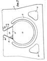
- a concrete drainage block has a drainage channel 12 of circular cross-section extending longitudinally therethrough and a slot 14 along an upper face of the block 10 communicates with the channel 12 along the length thereof.
- the upper and lower faces of the block 10 are parallel, with the lower face having a greater lateral dimension.
- the upper face slopes downwardly from the outer edge towards the slot 14.
- the sides of the block 10 are each defined by an inwardly angled section 16 and a vertical section 18 for a purpose hereinafter described.
- the block 10 can be end pressed by virtue of the provision of the unrestricted slot 14 and can be pressed by a semi-dry process or a conventional wet process.
- a pair of longitudinal through openings 20 are provided in the block 10 to reduce the weight of the block.
- An insert 24 defiling a lining for the slot 14 has side wolls 26 connected, for example by welding, with sloping edges of longitudinally spaced welded bridging portions 25 such that the walls 26 ore angled towards one another in an upward direction. Further the walls 26 have upper edge sections 26a turned laterally outwardly to seat in recesses in the upper face of the block 10 at the edges of the slot 14 so as to lie flush with the upper face.
- the welded bridging portions 25 terminate short of the upper end of the slot 14, and thus the slot 14 is unobstructed along the length of the lining over the distance above the welded bridging portions.
- the insert 24 is slidable into the slot 14 from an end of the moulded block 10 and can be secured in position by grouting or adhesive.
- the insert 24 may be cast into the block 10, having additional parts for keying into the concrete.
- the outwardly flaring side walls 26 of the insert 24 with the complementary flared sides of the slot 14, as well as the outwardly sloping side faces 28 of the bridging portions 25 extending between the side walls of the insert 24, enable the passage into the drainage channel of material which otherwise tends to clog the slot.
- the insert 24 also provides the block 10 with smooth and accurately formed surfaces over which drainage takes place.
- the blocks 10 When being positioned on site, ' the blocks 10 are laid end to end on d suitable base support which may extend up to the top of the angled section 16 of the side walls.
- the blocks 10 are secured to the support by grouting or the like and any suitable elements such as blocks or slabs can then be laid against the vertical sections 18 of the side walls.
- a slidable insert 24 may overlie the join between adjacent blocks 10 to facilitate connection of the blocks, and also any suitable form of connectors may be positioned through the longitudinal openings 20 to connect adjacent blocks together.
- the slot 20 can be easily cleaned by any appropriate cleaning tool passed along the slot which is unobstructed above the bridging portions 25.
- any appropriate cleaning tool passed along the slot which is unobstructed above the bridging portions 25.
- the bridging portions 25 are angled such that the tool is simply deflected upwardly and not permanently obstructed.
- With the lining being formed of metal it is also more easily cleaned and the edges of the slot are not susceptible to breakage.
- the use of the metal insert also reinforces the drainage block.
- the insert is preferably formed of stainless steel, is easy and inexpensive to manufacture and thus does not significantly increase the cost of production while obtaining the advantages outlined above.
- the ability to use different pressing techniques enables the longitudinal openings to be formed, thus reducing the weight of the component and facilitating transport etc.
- the drainage block may have other than the shaped sides as described and may be a block of conventional cross-section.
- the insert may be made of other than stainless steel and it may have other than the configuration described and shown.
- the insert may be produced from a material blank which is provided with cuts so as to define portions capable of being subsequently pressed and connected to form the lining having walls spaced apart by bridging parts, and keying parts if desired.
Landscapes
- Engineering & Computer Science (AREA)
- Civil Engineering (AREA)
- Structural Engineering (AREA)
- General Engineering & Computer Science (AREA)
- Architecture (AREA)
- Life Sciences & Earth Sciences (AREA)
- Agronomy & Crop Science (AREA)
- Mechanical Engineering (AREA)
- Road Paving Structures (AREA)
- Sewage (AREA)
Priority Applications (1)
| Application Number | Priority Date | Filing Date | Title |
|---|---|---|---|
| AT82304348T ATE12276T1 (de) | 1981-08-29 | 1982-08-18 | Drainage-blocks. |
Applications Claiming Priority (4)
| Application Number | Priority Date | Filing Date | Title |
|---|---|---|---|
| GB8126426 | 1981-08-29 | ||
| GB8126426 | 1981-08-29 | ||
| GB8129152 | 1981-09-26 | ||
| GB8129152 | 1981-09-26 |
Publications (2)
| Publication Number | Publication Date |
|---|---|
| EP0073601A1 true EP0073601A1 (fr) | 1983-03-09 |
| EP0073601B1 EP0073601B1 (fr) | 1985-03-20 |
Family
ID=26280611
Family Applications (1)
| Application Number | Title | Priority Date | Filing Date |
|---|---|---|---|
| EP19820304348 Expired EP0073601B1 (fr) | 1981-08-29 | 1982-08-18 | Eléments de drainage |
Country Status (3)
| Country | Link |
|---|---|
| EP (1) | EP0073601B1 (fr) |
| DE (1) | DE3262678D1 (fr) |
| DK (1) | DK157817C (fr) |
Cited By (3)
| Publication number | Priority date | Publication date | Assignee | Title |
|---|---|---|---|---|
| GB2448664A (en) * | 2007-04-25 | 2008-10-29 | Iain Bomphray | Slot drain |
| EP2336437A1 (fr) * | 2009-12-18 | 2011-06-22 | BIRCO Baustoffwerk GmbH | Elément de rainure |
| EP3754124A1 (fr) * | 2019-06-19 | 2020-12-23 | Carmine Franco Valente | Canal de drainage |
Citations (8)
| Publication number | Priority date | Publication date | Assignee | Title |
|---|---|---|---|---|
| GB559626A (en) * | 1942-08-25 | 1944-02-28 | Walter Emerson Doran | Improvements in or relating to pavement gutters or the like |
| DE1658522A1 (de) * | 1967-05-29 | 1970-10-22 | Pfuhler Betonroehren Gmbh & Co | Schlitzrohre mit eingebautem Gefaelle |
| US3714786A (en) * | 1970-08-03 | 1973-02-06 | Armco Steel Corp | Drainage culvert |
| GB1344236A (en) * | 1972-03-22 | 1974-01-16 | Evercrete Ltd | Drainage blocks |
| DE2249627A1 (de) * | 1972-10-11 | 1974-04-25 | Gotthold Wolfer | Wasserfuehrung mit schlitzrohr |
| US3898778A (en) * | 1974-01-10 | 1975-08-12 | Lennart G Erickson | Slotted drainage conduit and integral concrete floor |
| DE2620398A1 (de) * | 1976-05-08 | 1977-11-10 | Schmeing Geb | Sammelrinne, vorzugsweise aus kunststoff |
| BE866874A (fr) * | 1978-05-09 | 1978-09-01 | Dev Des Ind Mecaniques Sodemec | Avaloir pour tremies et autres tunnels routiers |
-
1982
- 1982-08-18 DE DE8282304348T patent/DE3262678D1/de not_active Expired
- 1982-08-18 EP EP19820304348 patent/EP0073601B1/fr not_active Expired
- 1982-08-27 DK DK385782A patent/DK157817C/da not_active IP Right Cessation
Patent Citations (9)
| Publication number | Priority date | Publication date | Assignee | Title |
|---|---|---|---|---|
| GB559626A (en) * | 1942-08-25 | 1944-02-28 | Walter Emerson Doran | Improvements in or relating to pavement gutters or the like |
| DE1658522A1 (de) * | 1967-05-29 | 1970-10-22 | Pfuhler Betonroehren Gmbh & Co | Schlitzrohre mit eingebautem Gefaelle |
| US3714786A (en) * | 1970-08-03 | 1973-02-06 | Armco Steel Corp | Drainage culvert |
| US3714786B1 (fr) * | 1970-08-03 | 1986-02-11 | ||
| GB1344236A (en) * | 1972-03-22 | 1974-01-16 | Evercrete Ltd | Drainage blocks |
| DE2249627A1 (de) * | 1972-10-11 | 1974-04-25 | Gotthold Wolfer | Wasserfuehrung mit schlitzrohr |
| US3898778A (en) * | 1974-01-10 | 1975-08-12 | Lennart G Erickson | Slotted drainage conduit and integral concrete floor |
| DE2620398A1 (de) * | 1976-05-08 | 1977-11-10 | Schmeing Geb | Sammelrinne, vorzugsweise aus kunststoff |
| BE866874A (fr) * | 1978-05-09 | 1978-09-01 | Dev Des Ind Mecaniques Sodemec | Avaloir pour tremies et autres tunnels routiers |
Cited By (4)
| Publication number | Priority date | Publication date | Assignee | Title |
|---|---|---|---|---|
| GB2448664A (en) * | 2007-04-25 | 2008-10-29 | Iain Bomphray | Slot drain |
| EP2336437A1 (fr) * | 2009-12-18 | 2011-06-22 | BIRCO Baustoffwerk GmbH | Elément de rainure |
| RU2471915C2 (ru) * | 2009-12-18 | 2013-01-10 | БИРКО ГмбХ | Элемент водоотвода |
| EP3754124A1 (fr) * | 2019-06-19 | 2020-12-23 | Carmine Franco Valente | Canal de drainage |
Also Published As
| Publication number | Publication date |
|---|---|
| DE3262678D1 (en) | 1985-04-25 |
| DK157817C (da) | 1990-07-23 |
| EP0073601B1 (fr) | 1985-03-20 |
| DK385782A (da) | 1983-03-01 |
| DK157817B (da) | 1990-02-19 |
Similar Documents
| Publication | Publication Date | Title |
|---|---|---|
| US4630966A (en) | Drainage channel | |
| US4553874A (en) | Slotted drainage grate with support | |
| US4731969A (en) | Roof tiles | |
| US6293067B1 (en) | Tie for forms for poured concrete | |
| EP1416091B1 (fr) | Support de montage pour relier avec des éléments de cadre d'un ensemble de constitution de tranchée et méthode associée de fabrication d'éléments de cadre | |
| US4742655A (en) | Device in concrete structures | |
| US4443981A (en) | Concrete form system | |
| EP0073601A1 (fr) | Eléments de drainage | |
| US5478169A (en) | Method and apparatus for forming a trench | |
| GB2104947A (en) | Drainage block | |
| CA1097857A (fr) | Grille essuie-pieds | |
| EP0410692A1 (fr) | Système de linteau | |
| EP0102746A1 (fr) | Bloc de drainage | |
| US4572701A (en) | Universal concrete screed system | |
| GB1598460A (en) | Edging members | |
| JP4494710B2 (ja) | トラフ | |
| JPH0223664Y2 (fr) | ||
| JPS5926028Y2 (ja) | コンクリ−ト型枠用セパレ−タのジヨイント台 | |
| US4571318A (en) | Method of constructing refractory runner | |
| JPH048578B2 (fr) | ||
| EP0297907A1 (fr) | Tuyau de drainage en matière plastique et sa fabrication | |
| JP3878455B2 (ja) | 芝生の見切材 | |
| JPS6312175Y2 (fr) | ||
| JP3459918B1 (ja) | 排水具およびその排水具を備える側溝ブロック | |
| KR960002488Y1 (ko) | 거푸집 간격 유지구 |
Legal Events
| Date | Code | Title | Description |
|---|---|---|---|
| PUAI | Public reference made under article 153(3) epc to a published international application that has entered the european phase |
Free format text: ORIGINAL CODE: 0009012 |
|
| AK | Designated contracting states |
Designated state(s): AT BE CH DE FR IT LI LU NL SE |
|
| 17P | Request for examination filed |
Effective date: 19830720 |
|
| RAP1 | Party data changed (applicant data changed or rights of an application transferred) |
Owner name: CHARCON LIMITED |
|
| GRAA | (expected) grant |
Free format text: ORIGINAL CODE: 0009210 |
|
| AK | Designated contracting states |
Designated state(s): AT BE CH DE FR IT LI LU NL SE |
|
| PG25 | Lapsed in a contracting state [announced via postgrant information from national office to epo] |
Ref country code: IT Free format text: LAPSE BECAUSE OF FAILURE TO SUBMIT A TRANSLATION OF THE DESCRIPTION OR TO PAY THE FEE WITHIN THE PRESCRIBED TIME-LIMIT;WARNING: LAPSES OF ITALIAN PATENTS WITH EFFECTIVE DATE BEFORE 2007 MAY HAVE OCCURRED AT ANY TIME BEFORE 2007. THE CORRECT EFFECTIVE DATE MAY BE DIFFERENT FROM THE ONE RECORDED. Effective date: 19850320 Ref country code: AT Effective date: 19850320 |
|
| REF | Corresponds to: |
Ref document number: 12276 Country of ref document: AT Date of ref document: 19850415 Kind code of ref document: T |
|
| REF | Corresponds to: |
Ref document number: 3262678 Country of ref document: DE Date of ref document: 19850425 |
|
| ET | Fr: translation filed | ||
| PG25 | Lapsed in a contracting state [announced via postgrant information from national office to epo] |
Ref country code: LU Free format text: LAPSE BECAUSE OF NON-PAYMENT OF DUE FEES Effective date: 19850831 |
|
| PLBE | No opposition filed within time limit |
Free format text: ORIGINAL CODE: 0009261 |
|
| STAA | Information on the status of an ep patent application or granted ep patent |
Free format text: STATUS: NO OPPOSITION FILED WITHIN TIME LIMIT |
|
| 26N | No opposition filed | ||
| PGFP | Annual fee paid to national office [announced via postgrant information from national office to epo] |
Ref country code: FR Payment date: 19920618 Year of fee payment: 11 |
|
| PGFP | Annual fee paid to national office [announced via postgrant information from national office to epo] |
Ref country code: DE Payment date: 19920702 Year of fee payment: 11 |
|
| PGFP | Annual fee paid to national office [announced via postgrant information from national office to epo] |
Ref country code: BE Payment date: 19920706 Year of fee payment: 11 |
|
| PGFP | Annual fee paid to national office [announced via postgrant information from national office to epo] |
Ref country code: SE Payment date: 19920818 Year of fee payment: 11 |
|
| PGFP | Annual fee paid to national office [announced via postgrant information from national office to epo] |
Ref country code: NL Payment date: 19920831 Year of fee payment: 11 |
|
| PGFP | Annual fee paid to national office [announced via postgrant information from national office to epo] |
Ref country code: CH Payment date: 19921104 Year of fee payment: 11 |
|
| PG25 | Lapsed in a contracting state [announced via postgrant information from national office to epo] |
Ref country code: SE Effective date: 19930819 |
|
| PG25 | Lapsed in a contracting state [announced via postgrant information from national office to epo] |
Ref country code: LI Effective date: 19930831 Ref country code: CH Effective date: 19930831 Ref country code: BE Effective date: 19930831 |
|
| BERE | Be: lapsed |
Owner name: CHARCON LTD Effective date: 19930831 |
|
| PG25 | Lapsed in a contracting state [announced via postgrant information from national office to epo] |
Ref country code: NL Effective date: 19940301 |
|
| NLV4 | Nl: lapsed or anulled due to non-payment of the annual fee | ||
| PG25 | Lapsed in a contracting state [announced via postgrant information from national office to epo] |
Ref country code: FR Effective date: 19940429 |
|
| REG | Reference to a national code |
Ref country code: CH Ref legal event code: PL |
|
| PG25 | Lapsed in a contracting state [announced via postgrant information from national office to epo] |
Ref country code: DE Effective date: 19940503 |
|
| REG | Reference to a national code |
Ref country code: FR Ref legal event code: ST |
|
| EUG | Se: european patent has lapsed |
Ref document number: 82304348.4 Effective date: 19940310 |