EP0073622A2 - Mehrleiterkoaxialkabeleinheit - Google Patents
Mehrleiterkoaxialkabeleinheit Download PDFInfo
- Publication number
- EP0073622A2 EP0073622A2 EP82304428A EP82304428A EP0073622A2 EP 0073622 A2 EP0073622 A2 EP 0073622A2 EP 82304428 A EP82304428 A EP 82304428A EP 82304428 A EP82304428 A EP 82304428A EP 0073622 A2 EP0073622 A2 EP 0073622A2
- Authority
- EP
- European Patent Office
- Prior art keywords
- clusters
- shielded
- cable assembly
- conductor
- ground wire
- Prior art date
- Legal status (The legal status is an assumption and is not a legal conclusion. Google has not performed a legal analysis and makes no representation as to the accuracy of the status listed.)
- Withdrawn
Links
Images

Classifications
-
- H—ELECTRICITY
- H01—ELECTRIC ELEMENTS
- H01B—CABLES; CONDUCTORS; INSULATORS; SELECTION OF MATERIALS FOR THEIR CONDUCTIVE, INSULATING OR DIELECTRIC PROPERTIES
- H01B7/00—Insulated conductors or cables characterised by their form
- H01B7/08—Flat or ribbon cables
- H01B7/0838—Parallel wires, sandwiched between two insulating layers
-
- H—ELECTRICITY
- H01—ELECTRIC ELEMENTS
- H01B—CABLES; CONDUCTORS; INSULATORS; SELECTION OF MATERIALS FOR THEIR CONDUCTIVE, INSULATING OR DIELECTRIC PROPERTIES
- H01B11/00—Communication cables or conductors
- H01B11/18—Coaxial cables; Analogous cables having more than one inner conductor within a common outer conductor
- H01B11/20—Cables having a multiplicity of coaxial lines
- H01B11/203—Cables having a multiplicity of coaxial lines forming a flat arrangement
Definitions
- This invention relates to coaxially shielded cables which are suitable for high fidelity electrical signal transmission, and a method of making same.
- Coaxially shielded cables are well known as the highest fidelity signal wiring for digital signals and analog signals through the microwave range. Their usefulness has been limited by cumbersome and time consuming termination methods. The need for coaxial cables which can be efficiently terminated has been recognized and addressed by previous inventions.
- U.S. Patent No.3,775,552 discloses a specific cable design with multiple coaxially shielded conductors in a flat cable which permits mass termination. That invention requires individual termination of a shield or ground wire for each signal wire, which requirement limits cable and connector density through imposition of a mechanical requirement which is often not an electrical requirement.
- U.S. Patent No.4,234,759 discloses a flat multiconductor coaxial cable assembly having a single ground wire for every pair of coaxial cable elements permitting somewhat higher signal carrying densities (in terms of the number of signal conductors per unit transverse width).
- a flat multiconductor cable assembly comprising a plurality of signal conductors positioned in longitudinal parallel and transversely co-planar relation, said signal conductors being electrically insulated from one another and arranged in clusters of one or more, each of said clusters being individually and coaxially surrounded by an electrically conductive shield, the individually shielded clusters being transversely spaced from one another, means for grounding the shields of said clusters, and a conductive element for electrically interconnecting the shields of said shielded clusters with said grounding means in the transverse direction, said conductive element being interwoven among the transversely spaced clusters and extending transversely of and in the longitudinal direction of the cable.
- the grounding means includes at least one uninsulated conductor extending in the longitudinal direction parallel to and transversely spaced from the shielded clusters, and is interwoven along with, and thus electrically interconnected with, the transversely connected clusters by the transverse conductive element.
- the shielded clusters together with the interwoven transverse conductive element and the grounding means are encapsulated in an insulating and protective covering, the covering being bonded to itself in the portions of the spaces between adjacent spaced clusters not occupied by the transverse conductive element.
- the present invention also provides a method for fabricating a flat multiconductor cable assembly having at least one ground wire conductor wherein a plurality of insulated signal conductors are positioned in longitudinally parallel and transversely co-planar relation with the ground wire conductor, and wherein the signal conductors are arranged in clusters of one or more, and the individual clusters are each coaxially surrounded by an electrically conductive shield, the shielded clusters being physically spaced from, but electrically interconnected with, one another and the ground wire conductor in the transverse direction, the method comprising:
- the method may also include the further step of
- Step (c) may also include the steps of feeding at least two uninsulated ground wire conductors into the bite of the pinch rollers, each of the uninsulated ground wire conductors being positioned outside of and spaced from the outermost cluster on the respective transverse edges of the cable assembly, and step (d) may include the substep of preforming the transverse conductor element in the form of a web by continuously spirally wrapping at least one uninsulated elongated conductor between the two uninsulated ground wire conductors prior to feeding the two uninsulated ground wire conductors and the between-suspended web to the bite of the pinch rollers.
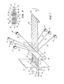
- FIGS 1 and 2 of the drawings illustrate a process for making a flat multiconductor cable 10 in accordance with the present invention.
- Cable 10 is especially useful in high fidelity signal transmission applications wherein ease of termination is required and especially where a relatively high signal density carrier is required, in terms of the cross-sectional area of the cable.
- cable 10 is to be viewed only as representative of the cables made in accordance with this invention, as a multitude of different flat cable configurations are possible, as will be immediately understood as a consequence of the following disclosure.
- a plurality of signal conductors of unlimited length are positioned in longitudinally parallel and transversely co-planar relation, with the signal conductors being electrically insulated from one another and arranged in clusters of one or more,each of the clusters further being individually and co-axially surrounded by an electrically conductive shield, with the individually shielded clusters being transversely spaced from one another.
- cable 10 includes signal conductors 12, 14 and 16 with surrounding insulation layers 18, 20 and 22 respectively.
- Conductors 12, 14 and 16 are shown as single strand round wire conductors, but multiple strands and/or other conductor cross section geometries can be used, such as flat metal or metallized polymer strips.
- PTFE expanded polytetrafluoroethylene
- the insulated conductor elements including elements 12, 14 and 16 are each surrounded by electrically conductive shields, such as shields 24, 26 and 28 respectively.
- the shield material is conventional and can be metal-foil or braided metal strands or even metallized polymer film.
- the function of the shields 24, 26, and 28 is to prevent extraneous inductive or capacitive coupling between adjacent signal conductors or outside sources, thereby eliminating cross-talk, and enabling close packing of the signal conductors.
- the individual shields also assure consistent signal transmission properties and thus minimize signal loss.
- Cable 10 as illustrated by way of example in Figure 1, has a total of six individually shielded conductor clusters 30, 32, 34, 36, 38 and 40, with the individual clusters being transversely spaced from one another all along the length of the cable 10.
- the six signal conductors including signal conductors elements 12, 14 and 16, are arranged in clusters having only one signal conductor per cluster.
- Certain other applications may dictate a different grouping of signal conductors, such as two or more, in each shielded cluster, and the scope of the present invention is intended to cover such multiconductor cables as well.
- the cable 10 is further provided with means for grounding the shields of the individually shielded clusters.
- an uninsulated ground wire 42 is positioned in cable 10 longitudinally parallel to the shielded clusters 30 ?? 40 throughout the entire length of the cable 10.
- Ground wire 42 is shown positioned outside the outermost shielded cluster at one transverse cable edge, namely, cluster 40 (see Figure 2), but other locations are possible.
- a plurality of ground wires 42 may be used, but more than one ground wire necessarily detracts from the high signal wire density of the cable because, in certain constructions, the ground wire may occupy the position of a shielded cluster.
- the ground wire 42 is transversely spaced from adjacent shielded clusters, such as cluster 40, for reasons which will become apparent from further discussions.
- the flat multiconductor cable assembly includes a conductive element for electrically interconnecting the shields of the shielded clusters with the grounding means in the transverse direction, with the transverse conductive element being interwoven among the transversely spaced clusters and extending intermittently in the longitudinal direction in the spaces between the clusters.
- cable 10 includes an electrically conducting screen 44 which is interwoven among clusters 30 ?? 40 and ground wire 42, passing alternately below some of the clusters and alternatively above others, with respect to the plane defined by the signal conductors, but physically contacting the respective outer electrical shields of the shielded clusters 30 .... 40 to establish the required electrical connection.
- Screen 44 can be of a conventional type made from two sets of parallel strands woven or bonded together with one set being angularly offset from the other, or screen 44 can be made from a continuous conductive sheet and then perforated. It is important, especially when screen 44 is made from a perforated foil, that the void fraction (ratio of area of the perforation ot the total screen area) be as large as possible for reasons that will become apparent from the succeeding discussion.
- the individual strands of the screen 44 can be seen in Figure 2 where they are schematically depicted.
- the strands appear discontinuous only because the screen 42 is oriented with the bias direction in the longitudinal direction of cable 10. It is understood that the individual conductor strands of screen 44 completely span the transverse direction of cable 10. For instance, although no strand of the transverse conductor screen 44 is shown connecting shield 26 with shield 28 at the cross section shown in Figure 2, such a connecting strand would appear in a section taken at another location along the longitudinal axis, at which other location no strand would be shown between shield 24 and shield 26 for the particular screen 44 orientation depicted in the cable 10 embodiment.
- screen material oriented with strands substantial perpendicular, or at any other angle, to the longitudinal axis is also contemplated by the present invention.
- a cross section such as shown in Figure 2 could, of course, show a screen strand completely spanning the cable 10 without apparent discontinuities or, at another location, show no transverse strand.
- the mesh size of screen 44 or the longitudinal distance between successive; perforations will, in general, be dictated by the electrical requirements of the cable.
- a web 60 (best seen in Figure 3) made up of a single uninsulated conductor element 62 is substituted for the screen 44 in the means for transversely electrically interconnecting the shielded clusters and the grounding means.
- this alternative construction where components similar to those disclosed with respect to the cable construction shown in Figures 1 and 2 are designated by the same reference numerals but with primes) two uninsulated ground wires 56, 58 are provided positioned outside all the shielded clusters to be grounded, namely shielded clusters 30', 32' ?? 38' and 40' in longitudinally parallel but transversely spaced relationship therewith.
- the uninsulated conductor element 62 is spirally wound between the ground wires 56 and 58 and thereby maintains firm physical, and therefore electrical, contact with ground wires 56,58 as well as physically contacting the electrical shields of the shielded clusters around which web 60 is interwoven.
- interwoven is used not only to designate a true weave wherein the longitudinal elements are physically captured by the transverse elements, and wherein the resulting structure is self-supporting, but also the configuration shown in Figures 1 to 4 wherein the transverse element (screen 44 - Figures 1 and 2; web 60 - Figures 3 and 4) follows the same serpentine path between the longitudinal elements (shielded clusters 30 .... 40 and ground wire 42 - Figures 1 and 2; shielded clusters 30' Vietnamese 40' and ground wires 56 to 58 - Figures 3 and 4; at every point along the longitudinal cable axis.
- the flat multiconductor cables of the present invention including the cables 10 and 10' shown in the drawings be encapsulated in an insulating and protective covering or "jacketed” as that term is conventionally used in the electrical cable art.
- cable 10 has a jacket 46 formed from a pair of sheets 48a, 48b of PVC or other conventional cable jacketing material, one sheet disposed on each side of the plane defined by the signal conductors 12, 14 and 16 and physically contacting the shielded clusters 30 .... 40, ground wire 42 and screen 44 sandwiched therebetween.
- Sheets 48a and 48b are bound together at the cable transverse edges 50, 52 and may also be bound to one or more of the shields including shields 24, 26 and 28, ground wire 42, and the transverse conductive screen 44.
- sheets 48a,48b are bound together between the adjacent clusters and ground wire in the portions of the longitudinal spaces not occupied by screen 44, such as is depicted at position 54 shown in Figure 2.
- This intermittent btt extensive binding between opposing sides of jacekt 46 in each longitudinal space between the shielded clusters and ground wires provides cable integrity and the maintenance of cluster-cluster spacing needed for accurate cable termination especially using automatic terminating apparatus.
- the method for fabricating the flat multiconductor cable assemblies of unlimited length includes the step of dividing sources of the unlimited length shielded clusters into two groups and positioning them proximate a pair of pinch rollers.
- sources 70, 72, 74, 76, 78 and 80 are shown for the shielded clusters 30, 32, 34, 36, 38 and 40 respectively.
- the individual sources depicted comprise spools with associated mounting and take-off apparatus and are positioned near co-operating pinch rollers 82,84 having bite 86.
- Sources 70, 74 and 78 are grouped and located above the XY plane which passes through bite 86, while the remaining three sources 72, 76 and 80 are below the XY plane.
- the method includes the additional step of continuously feeding the shielded clusters into the bite of the pinch rollers with the shielded clusters from one of the groups being interspersed with the shielded clusters from the other of the groups across the transverse width of the bite.
- shielded clusters 30, 34 and 38 from one group are fed to bite 86 from one side of the XY plane while the shielded clusters 32, 36 and 40 are fed to bite 86 from the other side of the XY plane.
- the shielded clusters fed from the two groups strictly alternate across the transverse width of the bite, with a shielded conductor from one group being adjacent a shielded conductor from the other group in alternating fashion.
- the method comprises the additional step of concurrently feeding at least one continuous uninsulated ground wire conductor of unlimited length into the bite of the pinch rollers in parallel with, and preferably transversely spaced from, said clusters.
- Ground wire 42 is shown emmanating from ground wire source 88 and being fed to bite 86 of rollers 82,84 adjacent and spaced from shielded cluster 40.
- the ground wire 42 is fed from one or the other side of the XY plane to alternate with the adjacent shielded cluster.
- the ground wire 42 is fed to bite 86 from the side of the XY plane opposite the side from which shielded cluster 40 is fed.
- the method includes the step of concurrently feeding an uninsulated transverse conductive element of unlimited longitudinal length into the bite of the rollers along the dividing plane and between the shielded clusters being fed from the two source groups.
- screen 44 is shown being fed to the bite 86 of pinch rollers 82 and 84 from source 90 along the XY plane.
- the screen conductor 44 spans both the shielded clusters and the uninsulated ground wire conductor in the transverse direction and has sufficient transverse flexibility to conform to the serpentine path shape wherein the screen 44 passes alternately to one side, between, and then to the other side of the adjacent shielded clusters with respect to the XY plane.
- the step of concurrently feeding at least one continuous uninsulated ground wire conductor into the bite of the pinch rollers preferably includes the step of feeding at least two uninsulated ground wire conductors into the bite of the pinch rollers, each of the uninsulated ground wire conductors being positioned outside of and spaced from the outermost cluster at the respective transverse edges of the cable assembly.
- the step of concurrently feeding an uninsulated transverse conductor element into the bite of the pinch rollers preferably includes the substep of preforming the transverse conductor element in the form of a web by spirally wrapping at least one uninsulated elongated conductor between the two ground wire conductors prior to feeding the ground wire conductors and the between-suspended web to the bite of the pinch rollers.
- ground wires 56 and 58 are shown being fed along the XY plane from ground wire sources 92 and 94 respectively.
- a web 60 is shown continuously being produced by apparatus designated generally 96, the web consisting of a single conductor strand 62 spirally wrapped around the parallel ground wire conductors 56,58.
- Apparatus 96 includes a motor 98 with the spinning arm 100 having wire guides 102 through which conductor 62 passes, and being fed from conductor source 104.
- the circular motion of the tip of arm 100 is shown schematically with arrows in Figure 3.
- Ground wires 56 and 58 and the web 60 suspended between them are shown lying in the XY plane in Figure 3 to underscore the fact that it is intended as a replacement for the screen 44 transverse conductor element shown being fed to the bite 86 in Figure 1.
- the ground wires 56, 58 supporting web 60 will, in general, serve the same function and therefore take the place of the single ground wire 42 using the construction of the cable assembly 10 pictured in Figure 4.
- the method of fabricating a flat multiconductor cable assembly preferably includes the additional step of encapsulating the shielded clusters, ground wire conductor, and interwoven transverse conductive element in an insulating and protective covering, with the encapsulating step including the step of binding the cover to itself through the portions of the spaces between adjacent clusters not occupied by the transverse conductor element.
- the multiconductor cable preform including the shielded clusters 30, 32, 34, 36, 38 and 40 and the ground wire 42 together with the interwoven screen 44 is shown emanating from the bite 86 of pinch rollers 82, 84 and subsequently being fed to the bite 106 of another pair of pinch rollers 108,110.
- PVC sheets 112 and 114 are also fed to bite 106 from respective sources (not shown).
- pinch rollers 108,110 the PVC sheets which are applied on either side of the cable preform contact the elements of the cable preform and most importantly are made to bind to one another not only at the cable transverse edges 50,52 but also in the spaces between adjacent shielded clusters 30, 32 etc. and ground wire 42 not taken up by the strands of screen 44.
- an insulated and protective jacket which is designated 116 on the finished cable emanating from the bite 106 of pinch rollers 108,110 such that binding between the opposing portions of the jacket occurs, is within-the capability of one of ordinary skill in the art, and can be accomplished by a variety of known processes such as by heating the PVC sheets 112,114 prior to feeding them to the bite 106 and/or by using heated pinch rollers, or other binding techniques may be used.
- the scope of the present invention is not restricted to the use of PVC as the jacket material and the selection of other insulating and protective covering materials is well within the skill of one working in the multiconductor cable fabrication art.
Landscapes
- Insulated Conductors (AREA)
- Communication Cables (AREA)
- Waveguides (AREA)
- Multi-Conductor Connections (AREA)
Applications Claiming Priority (2)
| Application Number | Priority Date | Filing Date | Title |
|---|---|---|---|
| US06/295,822 US4412092A (en) | 1981-08-24 | 1981-08-24 | Multiconductor coaxial cable assembly and method of fabrication |
| US295822 | 1981-08-24 |
Publications (2)
| Publication Number | Publication Date |
|---|---|
| EP0073622A2 true EP0073622A2 (de) | 1983-03-09 |
| EP0073622A3 EP0073622A3 (de) | 1983-07-27 |
Family
ID=23139367
Family Applications (1)
| Application Number | Title | Priority Date | Filing Date |
|---|---|---|---|
| EP82304428A Withdrawn EP0073622A3 (de) | 1981-08-24 | 1982-08-23 | Mehrleiterkoaxialkabeleinheit |
Country Status (3)
| Country | Link |
|---|---|
| US (1) | US4412092A (de) |
| EP (1) | EP0073622A3 (de) |
| JP (2) | JPS5878321A (de) |
Cited By (3)
| Publication number | Priority date | Publication date | Assignee | Title |
|---|---|---|---|---|
| EP0103430A1 (de) * | 1982-09-11 | 1984-03-21 | AMP INCORPORATED (a New Jersey corporation) | Abgeschirmtes elektrisches Kabel |
| EP0257855A3 (en) * | 1986-08-04 | 1989-04-26 | E.I. Du Pont De Nemours And Company | Cable having a corrugated septum |
| US4920234A (en) * | 1986-08-04 | 1990-04-24 | E. I. Du Pont De Nemours And Company | Round cable having a corrugated septum |
Families Citing this family (17)
| Publication number | Priority date | Publication date | Assignee | Title |
|---|---|---|---|---|
| ATE13605T1 (de) * | 1981-06-18 | 1985-06-15 | Amp Inc | Abgeschirmtes elektrisches kabel. |
| US4548661A (en) * | 1982-05-06 | 1985-10-22 | The United States Of America As Represented By The Secretary Of The Air Force | Method for assembling a multiconductor flat cable |
| US5245134A (en) * | 1990-08-29 | 1993-09-14 | W. L. Gore & Associates, Inc. | Polytetrafluoroethylene multiconductor cable and process for manufacture thereof |
| WO1992004719A1 (en) * | 1990-08-29 | 1992-03-19 | W.L. Gore & Associates, Inc. | Polytetrafluoroethylene insulated multiconductor cable and its manufacture |
| US6858797B2 (en) * | 2002-11-22 | 2005-02-22 | Gore Enterprise Holdings, Inc. | Support member for an assembly |
| WO2004049509A2 (en) * | 2002-11-22 | 2004-06-10 | Gore Enterprise Holdings, Inc. | Support member for an assembly |
| WO2010148165A2 (en) | 2009-06-19 | 2010-12-23 | 3M Innovative Properties Company | Shielded electrical cable |
| US9685259B2 (en) | 2009-06-19 | 2017-06-20 | 3M Innovative Properties Company | Shielded electrical cable |
| US12205732B2 (en) | 2010-08-31 | 2025-01-21 | 3M Innovative Properties Company | Shielded electric cable |
| EP2889881A1 (de) | 2010-08-31 | 2015-07-01 | 3M Innovative Properties Company | Abgeschirmtes Elektrokabel |
| CN102884592B (zh) | 2010-08-31 | 2017-12-26 | 3M创新有限公司 | 具有电介质间距的屏蔽电缆 |
| CA2809347A1 (en) | 2010-08-31 | 2012-03-08 | 3M Innovative Properties Company | Shielded electrical cable in twinaxial configuration |
| BR112013003296A2 (pt) | 2010-08-31 | 2016-06-07 | 3M Innovatie Properties Company | cabo elétrico blindado e montagem de cabo |
| US10147522B2 (en) | 2010-08-31 | 2018-12-04 | 3M Innovative Properties Company | Electrical characteristics of shielded electrical cables |
| BR112013003830A2 (pt) | 2010-08-31 | 2019-09-24 | 3M Innovative Properties Co | ''cabo elétrico blindado de alta densidade e outros cabos blindados,sistemas e métodos'' |
| WO2012039736A1 (en) | 2010-09-23 | 2012-03-29 | 3M Innovative Properties Company | Shielded electrical cable |
| US12183483B2 (en) * | 2021-12-10 | 2024-12-31 | W.L. Gore & Associates Gmbh | Cable unit |
Family Cites Families (16)
| Publication number | Priority date | Publication date | Assignee | Title |
|---|---|---|---|---|
| AT18535B (de) * | 1902-06-17 | 1904-12-10 | Julius Henrik West | Fernsprechkabel. |
| US2043044A (en) * | 1935-03-05 | 1936-06-02 | Gen Electric | Electric cable |
| US2286827A (en) * | 1940-09-24 | 1942-06-16 | American Steel & Wire Co | Electric cable and method of manufacture |
| FR1447361A (fr) * | 1965-06-16 | 1966-07-29 | Cie Generale De Fabrication De | Perfectionnements aux câbles conducteurs souples de sécurité |
| US3673315A (en) * | 1970-09-08 | 1972-06-27 | Belden Corp | Shielded cable |
| JPS4720223U (de) * | 1971-02-06 | 1972-11-07 | ||
| US3775552A (en) * | 1971-12-16 | 1973-11-27 | Amp Inc | Miniature coaxial cable assembly |
| JPS6042563B2 (ja) * | 1976-09-18 | 1985-09-24 | 住友電気工業株式会社 | テ−プ状電線 |
| DE2644252A1 (de) * | 1976-09-28 | 1978-03-30 | Siemens Ag | Flachbandleitung mit folienfoermigen durchbrochenen metallischen einlagen |
| DD134160A1 (de) * | 1977-12-07 | 1979-02-07 | Horst Zocher | Bandleitung mit elektrostatischem schirm |
| JPS5491790A (en) * | 1977-12-29 | 1979-07-20 | Junkosha Co Ltd | Flat cable |
| US4185162A (en) * | 1978-01-18 | 1980-01-22 | Virginia Plastics Company | Multi-conductor EMF controlled flat transmission cable |
| US4234759A (en) * | 1979-04-11 | 1980-11-18 | Carlisle Corporation | Miniature coaxial cable assembly |
| US4314737A (en) * | 1979-06-14 | 1982-02-09 | Virginia Patent Development Corp. | Cable assembly having shielded conductor and method of making same |
| US4281212A (en) * | 1979-06-14 | 1981-07-28 | Virginia Patent Development Corp. | Cable assembly having shielded conductor |
| ATE13605T1 (de) * | 1981-06-18 | 1985-06-15 | Amp Inc | Abgeschirmtes elektrisches kabel. |
-
1981
- 1981-08-24 US US06/295,822 patent/US4412092A/en not_active Expired - Lifetime
-
1982
- 1982-08-23 EP EP82304428A patent/EP0073622A3/de not_active Withdrawn
- 1982-08-24 JP JP57145608A patent/JPS5878321A/ja active Pending
-
1990
- 1990-08-23 JP JP1990087499U patent/JPH0330319U/ja active Pending
Cited By (3)
| Publication number | Priority date | Publication date | Assignee | Title |
|---|---|---|---|---|
| EP0103430A1 (de) * | 1982-09-11 | 1984-03-21 | AMP INCORPORATED (a New Jersey corporation) | Abgeschirmtes elektrisches Kabel |
| EP0257855A3 (en) * | 1986-08-04 | 1989-04-26 | E.I. Du Pont De Nemours And Company | Cable having a corrugated septum |
| US4920234A (en) * | 1986-08-04 | 1990-04-24 | E. I. Du Pont De Nemours And Company | Round cable having a corrugated septum |
Also Published As
| Publication number | Publication date |
|---|---|
| US4412092A (en) | 1983-10-25 |
| JPH0330319U (de) | 1991-03-26 |
| JPS5878321A (ja) | 1983-05-11 |
| EP0073622A3 (de) | 1983-07-27 |
Similar Documents
| Publication | Publication Date | Title |
|---|---|---|
| US4412092A (en) | Multiconductor coaxial cable assembly and method of fabrication | |
| US5084594A (en) | Multiwire cable | |
| US3984622A (en) | Multi-conductor cable harness with woven breakout cover and method of making same | |
| US4487992A (en) | Shielded electrical cable | |
| US4468089A (en) | Flat cable of assembled modules and method of manufacture | |
| US4564723A (en) | Shielded ribbon cable and method | |
| US4767891A (en) | Mass terminable flat cable and cable assembly incorporating the cable | |
| US3627903A (en) | Woven cable harness assembly and method of making same | |
| CA1174308A (en) | Flat electric signal cables with a connecting web | |
| JP3394041B2 (ja) | 電気ケーブル | |
| US5463186A (en) | Round electrical cable | |
| US4159394A (en) | Woven cut-line cable and method | |
| US4940426A (en) | High density woven wire harness assembly | |
| EP0197624B1 (de) | Leiterkabel | |
| EP0246115A2 (de) | Flaches gewebtes elektrisches Transmissionskabel | |
| US5262589A (en) | High velocity propagation ribbon cable | |
| DE2644252A1 (de) | Flachbandleitung mit folienfoermigen durchbrochenen metallischen einlagen | |
| US6689958B1 (en) | Controlled impedance extruded flat ribbon cable | |
| US4943688A (en) | Ribbon coaxial cable with offset drain wires | |
| GB2137907A (en) | Coaxial Cables | |
| EP0903757B1 (de) | Kabelzusammenbau für elektrische Signalleitungen | |
| US4967040A (en) | Screened electric cable provided with zones for rapid parallel connection | |
| JPS6222967Y2 (de) | ||
| JPH03254017A (ja) | スダレ状フラットケーブルの製造方法 | |
| JPH01149313A (ja) | フラットケーブルの製造方法 |
Legal Events
| Date | Code | Title | Description |
|---|---|---|---|
| PUAI | Public reference made under article 153(3) epc to a published international application that has entered the european phase |
Free format text: ORIGINAL CODE: 0009012 |
|
| AK | Designated contracting states |
Designated state(s): AT BE CH DE FR GB IT LI LU NL SE |
|
| PUAL | Search report despatched |
Free format text: ORIGINAL CODE: 0009013 |
|
| AK | Designated contracting states |
Designated state(s): AT BE CH DE FR GB IT LI LU NL SE |
|
| STAA | Information on the status of an ep patent application or granted ep patent |
Free format text: STATUS: THE APPLICATION IS DEEMED TO BE WITHDRAWN |
|
| 18D | Application deemed to be withdrawn |
Effective date: 19840328 |
|
| RIN1 | Information on inventor provided before grant (corrected) |
Inventor name: HANSELL III, GEORGE A. |