EP0073642A2 - Machine pour le montage des parties talon de chaussures - Google Patents
Machine pour le montage des parties talon de chaussures Download PDFInfo
- Publication number
- EP0073642A2 EP0073642A2 EP82304472A EP82304472A EP0073642A2 EP 0073642 A2 EP0073642 A2 EP 0073642A2 EP 82304472 A EP82304472 A EP 82304472A EP 82304472 A EP82304472 A EP 82304472A EP 0073642 A2 EP0073642 A2 EP 0073642A2
- Authority
- EP
- European Patent Office
- Prior art keywords
- shoe
- heel
- holddown
- shoe support
- support
- Prior art date
- Legal status (The legal status is an assumption and is not a legal conclusion. Google has not performed a legal analysis and makes no representation as to the accuracy of the status listed.)
- Withdrawn
Links
Images




Classifications
-
- A—HUMAN NECESSITIES
- A43—FOOTWEAR
- A43D—MACHINES, TOOLS, EQUIPMENT OR METHODS FOR MANUFACTURING OR REPAIRING FOOTWEAR
- A43D23/00—Single parts for pulling-over or lasting machines
- A43D23/02—Wipers; Sole-pressers; Last-supports; Pincers
-
- A—HUMAN NECESSITIES
- A43—FOOTWEAR
- A43D—MACHINES, TOOLS, EQUIPMENT OR METHODS FOR MANUFACTURING OR REPAIRING FOOTWEAR
- A43D21/00—Lasting machines
- A43D21/12—Lasting machines with lasting clamps, shoe-shaped clamps, pincers, wipers, stretching straps or the like for forming the toe or heel parts of the last
Definitions
- This invention is concerned with a machine for lasting heel seat portions of shoes comprising a shoe support, for supporting, bottom uppermost, a shoe comprising an upper on a last with an insole on the last bottom, heel seat lasting instrumentalities, a heel band, which serves to determine the position of a shoe supported by the shoe support, lengthwise of its bottom, in relation to the heel seat lasting instrumentalities and to clamp the heel end of such shoe thus positioned, a holddown, which serves to determine the heightwise position of a shoe supported by the shoe support in relation to said instrumentalities, and between which and the shoe support such shoe can be clamped thus positioned, first means for moving the shoe support inwardly towards the heel band, in a direction extending generally lengthwise of the bottom of a shoe supported by the shoe support, and second means for effecting relative heightwise movement between the shoe support and the holddown, the arrangement being such that a shoe positioned and clamped on the shoe support as aforesaid in relation to the heel seat lasting instrumentalities can then be operated upon thereby.
- the shoe support comprises a last pin on which the last is placed, the pin being accommodated in a hole drilled in the cone of the last. Whereas the drilling of these holes is intended to be standard, there is in practice a significant difference between successive lasts in the location of the hole. Furthermore, if the shoe bottom is brought into engagement with the holddown before the heel end of the shoe engages with the heel band, then the insole may be dislodged or damaged, e.g.
- the shoe can first engage with the holddown, establishing the heightwise location of the shoe in relation to the heel seat lasting instrumentalities, and then engage the heel band, establishing the lengthwise location, but without the risk of dislodging the upper on its last, lengthwise movement of the holddown relative to the heel band also minimising the risk of damage to the insole.
- the first means is effective firstly to movement the shoe support inwardly towards the heel band, to bring the heel end of a shoe supported by the shoe support into engagement with the band, then to separate them through a predetermined distance, the second means being effective, during such separation, to cause relative movement of approach to take place between the shoe support and the holddown, and thereafter again to move the shoe support inwardly towards the heel band to return the heel end of the shoe into engagement therewith, the arrangement being such that, during such return movement, the holddown, held in engagement with the shoe bottom by the action of the second means,is caused to move with the shoe support relative to the heel band.
- the shoe. is first located lengthwise in relation to the heel seat lasting instrumentalities and then heightwise, while out of engagement with the heel band, thereby avoiding dislodging during heightwise location.
- said first means comprises a piston-and-cylinder arrangement carried by a support linkage including a link arrangement having an extended and a retracted condition, the arrangement being such that firstly, with said link arrangement in its extended condition, the piston-and-cylinder arrangement is actuated to move the shoe support inwardly, then, with the piston-and-cylinder arrangement locked in position by locking means, the link arrangement is moved to its retracted condition thus to separate the shoe support and the heel band, and thereafter, after operation of the second means as aforesaid, the locking means is released and the piston-and-cylinder arrangement again actuated to move the shoe support inwardly towards the heel band.
- the initial lengthwise location of the shoe by engagement with the heel band remains unaffected by the variable link arrangement, while said arrangement ensures that the separating movement takes place through a predetermined distance.
- the first means is effective to move the shoe support inwardly towards the heel band and, during such movement, the second means is operated to cause relative heigthwise movement to take place between the shoe support and the holddown, the arrangement being such that the bottom of a shoe supported by the shoe support is caused to engage with the holddown prior to engagement of the heel band with the heel end of such shoe, continued inward movement of the shoe support after engagement of the shoe bottom with the holddown causing the holddown to move with the shoe support relative to the heel band.
- the shoe is effectively moved into an operative position, as determined by engagement with the heel band and the holddown, without detriment to the cycle time.
- the holddown by first engaging the holddown, the risk of the upper being dislodged on its last as aforementioned is avoided, and further, because the holddown can move in a direction generally lengthwise of the shoe bottom, the risk of buckling the insole or of damage to the insole is minimised.
- the arrangement of the second embodiment of the invention is especially suitable, though not exclusively so, for a machine in which the first and second means are pneumatically operated.
- the holddown is resiliently urged in a direction away from the heel band, so that effectively, at the point of first engagement, the holddown is displaced from its desired operating position, and the subsequent movement together with the shoe as aforesaid is then effective to bring the holddown into a desired location for the operation of the machine.
- the holddown is conveniently mounted for pivotal movement about an axis extending transversely of the bottom of a shoe supported by the shoe support.
- the axis is sufficiently spaced from the shoe-engaging surface of the holddown that the pivotal movement of the holddown does not significantly affect the heightwise position of said surface.
- the first machine in accordance with the invention now to be described is a machine for use in the combined lasting of heel seat and side portions of shoes using tacks and comprises a shoe support generally designated 10 (Figure 1), including a last pin 12 on which a shoe can be supported, bottom uppermost, and a toe rest 14, a heel band 16, heel seat lasting instrumentalities including two wiper plates 18, and side lasting instrumentalities generally designated 22, said instrumentalities comprising a plurality of fingers 24, a plurality of clamp pads 26 and lasting strap elements 28 extending over said fingers 24 and pads 26.
- the side lasting instrumentalities 22 are generally similar to those described in our co-pending European Patent Application No. 81304527.5.
- the wiper plates 18 form part of heel seat lasting instrumentalities which also include fastener-inserting devices generally designated 30 actuated by a pneumatically operated striker plate 32.
- the heel seat lasting instrumentalities and the heel band 16 are generally similar to those of the machine described in our U.K. Patent Application No.8020133.
- the shoe support 10 is mounted, on a bracket 36 ( Figure 4) upstanding from a base 38 of the machine frame, for swinging movement about a shaft 40 extending widthwise of the machine.
- the shoe support 10 comprises a column 42 on which the last pin 12 is supported, said column being mounted for sliding heightwise movement in a post 44 supported on the shaft 40. Said column also provides a support for the toe rest arrangement 14.
- first means comprising a piston-and-cylinder arrangement 46, a piston rod 48 of which is pivotally connected to the post 44.
- the cylinder is pivotally mounted, by a pin 50, in a bifurcated end of an S-shaped lever 52, itself mounted for pivotal movement about a pin 54 supported on a bracket 56 upstanding from the base 38.
- the lever 52 is pivotally supported, through two links 58, 60, on the bracket 56.
- the links 58, 60 are pivoted together to form a toggle arrangement at the "knee" of which is connected a piston rod 62 of a piston-and-cylinder arrangement 64 mounted on the bracket 56.
- locking means comprising a rod 66 mounted on the pin 50, said rod 66 having an internal bore which receives a further rod 68 pivotally connected to the post 44 of the shoe support 10; such pivotal connection may be the same as that for the piston rod 48.
- Carried by the rod 66 is a pneumatic clamp arrangement 70, which is effective to clamp said further rod 68 in the rod 66, and thus clamp up the piston-and-cylinder arrangement 46 and its piston rod 48. In this way, effectively a rigid link is created between the pin 50 and the post 44 of the shoe support.
- the first machine in accordance with the invention also comprises second means for moving the shoe support 10 heightwise to bring the bottom of a shoe supported thereby, in its heel seat region into engagement with the holddown 20.
- the column 42 extends through the post and projects downwardly from the under-side thereof, there being pivotally connected to the lower end of the column a foot 74 which engages with a wedge member 76 movable along a horizontal path, on the base 58 of the machine frame, by means of a piston-and-cylinder arrangement 78 supported by a bracket on said base. Operation of said piston-and-cylinder arrangement is thus effective, through the wedge member 76, to raise or lower the column 42 and thus the. shoe support 10.
- the second machine in accordance with the invention now to be described is generally similar, except as hereinafter described, to the machine described in the aforementioned European Patent Application and is a machine for use in the combined lasting of heel seat and side portions of shoes using adhesive.
- the machine thus comprises a shoe support 110 ( Figure 2) on which a shoe, comprising an upper U on a last with an insole I on the last bottom, can be supported bottom uppermost-.
- the machine further comprises heel seat wiping instrumentalities 112, a heel band 114, and two side lasting assemblies generally designated 116.
- the shoe support 110 comprises toe and heel supports for the shoe, said supports being carried on a support post (not shown) which is mounted for heightwise movement within a column 142, a piston-and-cylinder arrangement 178 being supported at the base of column 142 for effecting heightwise movement of the shoe support.
- the column 142 is mounted for swinging movement about an axis 140 extending widthwise of the machine, a piston-and-cylinder arrangement (not shown) being mounted on the machine frame and being operatively connected to the column for effecting such swinging movement, and thus for effecting swinging movement of the shoe support from an initial, loading, position to an operative position.
- the piston-and-cylinder arrangement (not shown) and the piston-and-cylinder arrangement 178 constitute respectively first and second means of the machine. Both piston-and-cylinder arrangements referred to are pneumatically operated.
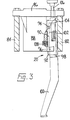
- a holddown generally designated 20 ( Figure 3) is also provided, which is carried on a bridge member 86 supported between two vertical plates 82, 84 of the machine frame, as now to be described.
- the bridge member 86 carries a support block 88 having a channel 90 formed therein for receiving a support element 92 mounted for pivotal movement on a pin 94 in side wall portions of the block 88.
- the support element 92 also has a channel 96 in which is accommodated a necked-down portion 98 of a holddown foot 100, a plate 102 being secured across the open side of the channel 90 thus to prevent the necked-down portion 98 from falling out.
- a plate 104 which supports, captive therein, an adjusting screw 106, a lower end of which is threadedly received in the necked-down portion 98, rotation of the screw 106 thus serving to vary the heightwise position of the holddown foot.
- the support element 92, and thus the holddown foot 100, is urged about the pin 94 towards the front plate 82 by means of a spring 108 accommodated in a recess formed in the forward face of the channel 90 of the support block.
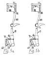
- the pneumatic clamp arrangement 70 is operated and the toggle arrangement 58, 60 is then moved to its retracted condition, thus effecting a forward movement of the shoe support 10 through a predetermined distance, separating the shoe support 10 from the heel band 16 to disengage the heel end of the shoe from the latter ( Figure 5b). While the shoe support and heel band are thus separated, the piston-and-cylinder arrangement 78 is operated whereby, through the action of the wedge member 76, the shoe support is raised to bring the heel seat region of the shoe bottom into engagement with the holddown foot 100, at this time spring-urged into its forward condition.
- the heel seat region is thus located in a heightwise direction relative to the plane of the wiper plates 18 of the heel seat lasting instrumentalities (Figure 5c).
- the pneumatic clamp arrangement 70 is released and the piston-and-cylinder arrangement 46 is again operated to return the shoe support 10 into its lengthwise location, with the heel end of the shoe in engagement with the heel band 16 ( Figure 5d).
- the holddown 20 is caused to pivot about the pin 94, so that it remains in fixed engagement with the heel seat region of the shoe located thereby.
- the shoe support 10 is locked in its position by means of a wedge member (not shown).
- a shoe is placed on shoe support 110, in its loading position, and the first and second means are actuated to move the shoe from the loading position to an operative position, as determined by engagement with the holddown 20 and heel band 114.
- the pneumatic circuitry is so arranged that the heel end of the shoe is caused to engage with the holddown foot 100 prior to its engagement with the heel band. More particularly, the shoe support 110 is first caused to swing from its initial, loading, position. After a short time period, timed by means of a timer device 150 ( Figure 2), the piston-and-cylinder arrangement 178 is actuated to move the shoe support 110 upwardly, while said swinging movement is also continued.
- the speed of the swinging movement is regulated by the operator using a flow control valve 152, by which the pneumatic pressure can be varied.
- the pressure of the pneumatic fluid supplied to said arrangement 178 is regulated by a conventional regulator valve.
- a control arrangement responsive to the distance moved by the shoe support 110 as it swings may be used, e.g. a trip valve, by which the supply of pneumatic fluid to the arrangement 178 can be initiated. Whichever control system is used, as the shoe support 110 is moved inwards and upwards as aforesaid, the heel seat portion of the insole I is first brought into engagement with the holddown 20.
- the holddown foot 100 is urged by the spring 108 forwardly of the position which it is intended it should occupy during the subsequent lasting operation.
- the holddown foot is in its forward position and is caused to pivot about the pin 94, during the inward movement of the shoe support, by engagement with the shoe, so that, when the heel band engages the heel end of the shoe, the holddown is positioned appropriately for the subsequent lasting operation.
- the amount of such movement of the holddown 20 will of course depend on a number of factors, including the relationship between the backseam region of the shoe and the last pin socket formed in the cone of the last. It is not expected, however, that the variations in holddown movement will be sufficiently significant to warrant setting up for each shoe style, although, if such an adjustment became necessary, appropriate adjustable limit means could be provided readily for this purpose.
- the second machine described above is intended for use with pre-cemented work, and consequently does not require adhesive-applying means to be provided (cf. the machine described in the aforementioned European Patent Application).
- the invention is, however, also applicable to a machine in which such adhesive-applying means is provided, in which case it may be necessary, if nozzles are used to apply adhesive from the backseam region progressively along the opposite side portions of the shoe bottom, for the holddown 20 to be temporarily retracted to allow passage of such nozzles.
- the holddown since, in returning the holddown 20 into engagement with the insole after passage of the nozzles, the holddown can then be positioned in a desired operative location in relation to the shoe bottom, it will be desirable that the holddown is spring-urged into the position it is intended to occupy during the subsequent lasting operation, rather than toewardly of such position.
- first and second machines described above are for use in the combined lasting of heel seat and side portions of shoes, it will be appreciated that the invention is also applicable to machines for use in lasting heel seat portions only of shoes.
Landscapes
- Footwear And Its Accessory, Manufacturing Method And Apparatuses (AREA)
Applications Claiming Priority (4)
| Application Number | Priority Date | Filing Date | Title |
|---|---|---|---|
| GB8126399 | 1981-08-28 | ||
| GB8126399 | 1981-08-28 | ||
| GB8212461 | 1982-04-29 | ||
| GB8212461 | 1982-04-29 |
Publications (2)
| Publication Number | Publication Date |
|---|---|
| EP0073642A2 true EP0073642A2 (fr) | 1983-03-09 |
| EP0073642A3 EP0073642A3 (fr) | 1985-10-30 |
Family
ID=26280606
Family Applications (1)
| Application Number | Title | Priority Date | Filing Date |
|---|---|---|---|
| EP82304472A Withdrawn EP0073642A3 (fr) | 1981-08-28 | 1982-08-25 | Machine pour le montage des parties talon de chaussures |
Country Status (1)
| Country | Link |
|---|---|
| EP (1) | EP0073642A3 (fr) |
Cited By (2)
| Publication number | Priority date | Publication date | Assignee | Title |
|---|---|---|---|---|
| DE3714919A1 (de) * | 1987-05-05 | 1988-11-24 | Schoen & Cie Gmbh | Leistenausricht- und haltevorrichtung an einer fersenzwickmaschine |
| CN114209127A (zh) * | 2021-12-23 | 2022-03-22 | 丽荣鞋业(深圳)有限公司 | 脱鞋楦装置 |
Family Cites Families (4)
| Publication number | Priority date | Publication date | Assignee | Title |
|---|---|---|---|---|
| US3409921A (en) * | 1967-04-19 | 1968-11-12 | Schon & Compagnie Gmbh Fa | Combined heel, forepart, and cement lasting machine |
| US3918394A (en) * | 1973-08-06 | 1975-11-11 | Int Shoe Machine Corp | Machine for cement lasting |
| GB2052950B (en) * | 1979-07-16 | 1983-02-16 | British United Shoe Machinery | Machine for lasting heel seat portions of shoes |
| EP0050429B2 (fr) * | 1980-10-16 | 1992-01-22 | British United Shoe Machinery Limited | Machine pour monter les parties marginales d'empeignes |
-
1982
- 1982-08-25 EP EP82304472A patent/EP0073642A3/fr not_active Withdrawn
Cited By (3)
| Publication number | Priority date | Publication date | Assignee | Title |
|---|---|---|---|---|
| DE3714919A1 (de) * | 1987-05-05 | 1988-11-24 | Schoen & Cie Gmbh | Leistenausricht- und haltevorrichtung an einer fersenzwickmaschine |
| CN114209127A (zh) * | 2021-12-23 | 2022-03-22 | 丽荣鞋业(深圳)有限公司 | 脱鞋楦装置 |
| CN114209127B (zh) * | 2021-12-23 | 2023-08-15 | 丽荣鞋业(深圳)有限公司 | 脱鞋楦装置 |
Also Published As
| Publication number | Publication date |
|---|---|
| EP0073642A3 (fr) | 1985-10-30 |
Similar Documents
| Publication | Publication Date | Title |
|---|---|---|
| US5722103A (en) | Toe and side and heel lasting machine and method of lasting | |
| US4082060A (en) | Cement side and heel lasting machine | |
| EP0073642A2 (fr) | Machine pour le montage des parties talon de chaussures | |
| US4400839A (en) | Machine for lasting heel seat portions of shoes | |
| EP0100636B1 (fr) | Machine pour tendre la pointe avec une pince de talon ajustable | |
| US4485512A (en) | Machines for lasting heel seat portions of shoes | |
| US2153570A (en) | Machine for operating on shoes | |
| US2727257A (en) | Machine for operating on shoes | |
| US3931788A (en) | Adhesive extruding nozzle-guidance arrangements | |
| US5271117A (en) | Machine for use in the manufacture of shoes | |
| US2501789A (en) | Sole attaching machine | |
| GB2118867A (en) | Machine for lasting side portions of shoes | |
| USRE30646E (en) | Cement side and heel lasting machine | |
| US4380524A (en) | Cement applying machine and method | |
| EP0055107A2 (fr) | Machine pour le montage combiné de pointes et de parties marginales des tiges de chaussure | |
| US5136745A (en) | Shoe support | |
| EP0511811B1 (fr) | Dispositif pour la fabrication de chaussures | |
| US2108171A (en) | Lasting machine | |
| CA1186461A (fr) | Machines de montage d'appuis pour talons de chaussures | |
| US4404700A (en) | Machine for lasting side portions of shoes | |
| US1968146A (en) | Machine for shaping shoe uppers | |
| EP0093608B1 (fr) | Dispositif pour transporter une pièce | |
| US4593423A (en) | Lasting heel seat and side portions of a shoe | |
| US2357841A (en) | Lasting machine | |
| US1993128A (en) | Sole pressing machine |
Legal Events
| Date | Code | Title | Description |
|---|---|---|---|
| PUAI | Public reference made under article 153(3) epc to a published international application that has entered the european phase |
Free format text: ORIGINAL CODE: 0009012 |
|
| AK | Designated contracting states |
Designated state(s): DE FR GB IT |
|
| 17P | Request for examination filed |
Effective date: 19830826 |
|
| RAP1 | Party data changed (applicant data changed or rights of an application transferred) |
Owner name: USM CORPORATION Owner name: BUSM CO. LIMITED |
|
| PUAL | Search report despatched |
Free format text: ORIGINAL CODE: 0009013 |
|
| AK | Designated contracting states |
Kind code of ref document: A3 Designated state(s): DE FR GB IT |
|
| RAP1 | Party data changed (applicant data changed or rights of an application transferred) |
Owner name: BRITISH UNITED SHOE MACHINERY LIMITED |
|
| STAA | Information on the status of an ep patent application or granted ep patent |
Free format text: STATUS: THE APPLICATION IS DEEMED TO BE WITHDRAWN |
|
| 18D | Application deemed to be withdrawn |
Effective date: 19880301 |
|
| RIN1 | Information on inventor provided before grant (corrected) |
Inventor name: NEWTON, ROBERT ALFRED Inventor name: HARTSHORN, FRANK Inventor name: FLANDERS, JAMES ROBERT Inventor name: BERRILL, WILLIAM HERBERT |