EP0073682A1 - Transducteur éléctroacoustique pour utilisation en présence de vibrations et son procédé de fabrication - Google Patents
Transducteur éléctroacoustique pour utilisation en présence de vibrations et son procédé de fabrication Download PDFInfo
- Publication number
- EP0073682A1 EP0073682A1 EP82304602A EP82304602A EP0073682A1 EP 0073682 A1 EP0073682 A1 EP 0073682A1 EP 82304602 A EP82304602 A EP 82304602A EP 82304602 A EP82304602 A EP 82304602A EP 0073682 A1 EP0073682 A1 EP 0073682A1
- Authority
- EP
- European Patent Office
- Prior art keywords
- backplate
- spring
- opening
- transducer
- diaphragm
- Prior art date
- Legal status (The legal status is an assumption and is not a legal conclusion. Google has not performed a legal analysis and makes no representation as to the accuracy of the status listed.)
- Granted
Links
Images



Classifications
-
- H—ELECTRICITY
- H04—ELECTRIC COMMUNICATION TECHNIQUE
- H04R—LOUDSPEAKERS, MICROPHONES, GRAMOPHONE PICK-UPS OR LIKE ACOUSTIC ELECTROMECHANICAL TRANSDUCERS; ELECTRIC HEARING AIDS; PUBLIC ADDRESS SYSTEMS
- H04R19/00—Electrostatic transducers
-
- H—ELECTRICITY
- H04—ELECTRIC COMMUNICATION TECHNIQUE
- H04R—LOUDSPEAKERS, MICROPHONES, GRAMOPHONE PICK-UPS OR LIKE ACOUSTIC ELECTROMECHANICAL TRANSDUCERS; ELECTRIC HEARING AIDS; PUBLIC ADDRESS SYSTEMS
- H04R1/00—Details of transducers, loudspeakers or microphones
- H04R1/06—Arranging circuit leads; Relieving strain on circuit leads
Definitions
- the present invention relates to an electroacoustical transducer assembly, in general, and to the apparatus for urging a backplate into cooperative engagement with a vibratile diaphragm in such a transducer, in particular.
- Capacitance-type electroacoustical transducers are well known in the art.
- a diaphragm having an insulative layer and an electrically conductive surface has its insulative layer in contact with a grooved, irregular, electrically conductive surface of a substantially inflexible disc or backplate.
- the periphery of the diaphragm is maintained in a fixed position with respect to the transducer housing and a spring force urges said backplate into tensioning engagement with said diaphragm.
- a dc bias voltage when an ac signal is superimposed on said dc bias, the diaphragm is stressed such that oscillatory formations develop causing an acoustical wavefront to be propagated from said diaphragm.
- a received acoustical wavefront impinging on the diaphragm produces a variable voltage across said capacitor electrodes.
- the distance to the subject to be photographed is determined by the well-known technique of measuring the round-trip time-of-flight of a burst of ultrasonic energy between an ultrasonic energy generating transducer and said subject to be photographed.
- This type of transducer has both transmitting and receiving modes of operation. In the transmit mode, an electronic device causes the transducer to transmit a burst of ultrasonic energy toward a subject.
- this same transducer detects the previously transmitted ultrasonic energy reflected from said subject that impinges on said transducer's vibratile diaphragm.
- the elapsed time from initiation of energy transmission until receipt of an echo of said transmitted energy is a fairly accurate measure of subject distance.
- an electrically conductive spring member is employed to urge the backplate of a transducer into cooperative engagement with the vibratile diaphragm of said transducer.
- the spring member also forms a part of the electrical circuit or path that electrically couples the transducer to electronic circuitry external of said transducer.
- a capacitance-type transducer is operated in an environment where it is subjected to excessive mechanical vibrations after it has transmitted an ultrasonic burst of energy toward, for example, an object whose distance is to be determined while said transducer is in its receive mode waiting for the receipt of an echo of said ultrasonic burst of energy from said object, when said excessive vibrations occur, a spurious object detect signal may be generated by the transducer if the intensity of the vibrations are sufficient to temporarily separate the electrically conductive, signal-carrying spring member from its assoc iated backplate.
- vibrations may also cause a slight lateral movement of the spring member with respect to its associated backplate and cause a change in the amount of tensioning of the vibratile diaphragm produced by said spring member, thereby causing a change in the effective gain or amplification associated with said capacitance-type transducer by such relative spring member movement.
- the electrically conductive diaphragm tensioning spring of a capacitance-type transducer employed to urge the backplate into proper tensioning engagement with the vibratile diaphragm of said transducer and to couple the transducer to external circuitry, is laser- welded to the transducer backplate in order to preclude undesirable spurious signal-generating relative movement between said backplate and said spring. Attaching the spring to the backplate in this manner enables the transducer to be effectively employed in a vibratory environment. However, welding these components together necessitates employing additional assembly steps in the transducer assembly process which has a substantial impact on transducer assembly costs.
- An electroacoustical transducer assembly comprises a backplate having an electrically conductive major surface and having another electrically conductive surface, that is electrically connected to said major surface, on the opposite side thereof? a diaphragm having electrically conductive and electrically nonconductive surfaces on opposite sides thereof; and an electrically conductive spring for connecting said backplate to an electrical circuit, for urging the major backplate surface into engagement with said electrically nonconductive diaphragm surface and for properly tensioning the diaphragm; characterized by cooperating means on the spring and on the backplate for providing interfering engagement therebetween to fixedly attach the spring to the backplate.
- Transducer 10 includes cylindrical electrically conductive housing 12 having open end 14 at one end and partially closed perforated end 16 at the other. Electrically conductive housing 12 also includes flanged portion 18 near open end 14 of said housing 12. Flat vibratile diaphragm 20, having electrically conductive and electrically non-conductive surfaces on opposite sides thereof, extends across opening 14 and is positioned between circular diaphragm support ring 22: 12 with its and said housing/electrically conductive surface adjacent said opening 14. Diaphragm 20 is made from a polyimide film sold by the E.I.
- Diaphragm support ring 22 is of circular cross section with an opening 23 through the centre thereof and has a flanged end for cooperative engagement with flanged portion 18 of housing 12.
- Stainless steel leaf spring 32 provides the force that maintains backplate 24 in proper cooperative engagement with diaphragm 20.
- the transducer components described in Figure lA are in the positions shown in Figure 2 and when fully assembled, said transducer components described with respect to Figure 1A are in the positions shown in Figure 3 and 4.
- the transducer of Figures lA-4 is assembled by placing a light, uniform, radial force on diaphragm 20 for the purpose of temporarily maintaining said diaphragm in a relatively flat plane and then positioning said diaphragm over opening 14 ( Figure 1A) of housing 12. Diaphragm 20 is then "dished" or formed into the crowned shape of a subsequently mating backplate member.
- Figure lB is an enlargement of detail lB in Figure 3
- Figure lC is a sectional view taken on the line lC-lC in Figure 1B
- Figure 5 is a partial sectional view taken on line 5-5 in said Figure 3.
- Moving spring 32 of transducer 10 into interference engagement with boss 30 would ordinarily require an excessive amount of spring movement force on spring 32 in order to cut into said boss 30 if means were not provided to reduce the amount of force required to produce said interference engagement.
- One such force reducing arrangement is shown in Figures lB, lC, 3 and 5.
- the periphery of opening 36 in leaf spring 32 includes tapered side 36A at one end and opposed parallel cutting edges 36B at the other.
- raised portion or boss 30 of backplate 24 includes striated outer surface 30A.
- the stria are parallel to one another and are equally spaced around the periphery, generally at right angles to surface 28 ( Figure lA) of backplate 24.
- boss 30 of backplate 24 initially engages tapered sides 36A of opening 36, and then striated surface 30A of boss 30 engages opposed parallel cutting edges 36B.
- striating surface 30A of boss 30 there is less material on boss 30 for cutting edges 36B to cut through and therefore less force required to place opening 36 of leaf spring 32 in interference engagement with boss 30 by this spring 32-to-boss 30 cutting movement,
- Opening 34A in ring 22 is a T-shaped opening and when spring 32 is in the position shown in Figures 3 and 4, narrowed end 38 of spring 32 moves or springs into the vertical portion of T-shaped opening 34A as shown in Figure 6, said Figure 6 being a partial elevational view taken on the line 6-6 in Figure 5.
- spring 32 when spring 32 is in the position shown in Figure 3, bent and narrowed end 40 of said spring 32 located opposite said narrowed spring end 38 becomes interlocked with the outer surface of ring 22.
- spring 32 is placed in a fixed relationship with respect to backplate 24 as explained above, and movement of said spring 32 parallel to surface 28 of backplate 24 is limited by the engagement of the non-narrowed portion of spring 32 with the inner cylindrical surface of support ring 22.
- leaf spring 32 When in the position shown in Figures 3 and 4, the centre portion of leaf spring 32 presses against backplate 24 and the ends of leaf spring 32 rest against the side walls in openings 34A, 34B of said support ring 22. With leaf spring 32 so positioned, diaphragm 20 will be in proper cooperative engagement with crowned surface 26 of backplate 24 and said leaf spring 32 will be in electrical contact with the crowned and grooved surface 26 of backplate 24 through the electrically conductive aluminium of said backplate 24.
- FIG. 12 is an enlarged top view of transducer 74, a view that is similar to the top view of transducer 10 shown in Figure 3.
- Figure 13 is a cross-sectional view taken on the line 13-13 in Figure 12.
- leaf spring 76 and opening 78 in said leaf spring 76 are approximately the same as leaf spring 32 and opening 36 in transducer 10 with the exception being the slightly longer length of opening 78.
- transducer 74 in Figure 12 is the same as transducer 10 in , for example, Figure 3.
- a capacitor-type electroacoustical transducer of the type described above has been employed in object distance determining ranging systems.
- One such system is described in US Patent No.4199246 to MUGGLI.
- a high frequency electrical signal is impressed on narrowed end 38 of spring 32 and terminal 42 of transducer 10 through conductors 44, 46, respectively, (Figs. 3 and 4) which cause the diaphragm of transducer 10 to vibrate and thereby propagate an acoustical wavefront toward an object whose distance is to be measured.
- An echo of said acoustical wavefront impinging on transducer 10 will cause diaphragm 20 of transducer 10 to vibrate and thereby produce an object detect signal between said conductors 44, 46.
- the time of flight of said acoustical wavefront or signal from transmission to receipt of an echo of said acoustical signal provides a fairly good measure of object distance.
- Both the acoustical wavefront generating transmit signal and the vibrating diaphragm produced echo signal appear at the same transducer 10 conductors (conductors 44, 46), but at different points in time.
- a typical transducer 10 transmit and receive signal 48 is shown in drawing Figure 7.
- voltage variations of transmit and receive signal 48 are shown as a function of time.
- Signal 48 has three fairly distinct time-dependent divisions or segments. Segment 50 constitutes the transmit portion and segment 52 constitutes the receive portion, respectively, of transmit and receive signal 48. That portion of transmit and receive signal 48 between transmit portion 50 and receive portion 52 constitutes background, electronic and/or other noise present on transducer 10 conductors 44, 46 after the completion of transmit portion 50 of transmit and receive signal 48 but before the receipt of receive portion 52 of said signal 48. It is during this noise portion of transmit and receive signal 48 that the electronics associated with transducer 10 is listening for a reflection, echo or receipt of a previously transmitted transmit signal. If a spurious signal of sufficient magnitude and duration should appear between conductors 44, 46 of transducer 10 during this listening interval of time, an erroneous object distance signal may be generated by a ranging system incorporating such a transducer.
- leaf spring 32 of transducer 10 forms a portion of the electrical circuit between external circuitry and grooved and crowned electrically conductive surface 26 of backplate 24.
- the electrical connection between leaf spring 32 and backplate 24 is maintained, in part, by the spring force of spring 32 causing said spring 32 to press on electrically conductive surface 28 of backplate 24, a surface that is electrically connected to said grooved and crowned electrically conductive surface 26 of backplate 24.
- T l is a point in time when, without the coupling apparatus of the present invention, the electrical connection between leaf spring 32 and backplate 24 would be broken
- T 2 is the point in time when said broken electrical connection between spring 32 and backplate 24 would be reestablished.
- voltage oscillations 54 may be generated by such separation having a magnitude approximating that of a true echo or receive signal which could falsely indicate to the above-mentioned electronics associated with transducer 10 that a particular object had been detected, a false signal magnitude that may be several orders of magnitude greater than background noise 56, for example, noise/that would otherwise occur between times T 1 and T 2 if a separation of leaf spring 32 from backplate 24 should not occur.
- a receive signal that might otherwise have the amplitude of receive signal 58 before such lateral spring member movement occurred may have the lower amplitude of receive signal 60 after lateral spring member movement, or vice versa.
- the object distance determining electronics associated with transducer 10 (not shown) is normally sensitive to receive signal amplitude and a change in receive signal amplitude resulting from such lateral spring member movement may also produce an erroneous object distance signal.
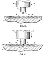
- FIG. 10 shows backplate 24 nested in backplate support member 64 just prior to the forming of raised portion 30 in said backplate 24, and Figure 11 shows backplate 24 after said raised portion 30 has been formed, but before a portion of the die-forming tool 62 that produced said raised portion 30 has been withdrawn from said backplate 24.
- backplate 24 is positioned in backplate support member 64 with its relatively flat surface 28 resting on said member 64 and with the grooved and crowned surface 26 of backplate 24 that is opposite said flat surface 28 projecting upward from support member 64.
- Vertically movable cylindrical rod 66 having narrowed portion 68 at one end thereof has removably mounted cylindrical punch 70 attached to said narrowed rod portion 68.
- Force transmitting cylindrical rod 66 coupled to force producing means (not shown) selectively couples the proper magnitude force to said removable punch 70 and to backplate 24.
- rod 66 is moved vertically downward to the point where punch 70 engages the geometrical center of curved and grooved surface 26 of backplate 24 and causes the center portion of surface 28 to be extruded a predetermined depth into the cylindrical extrusion die 72 portion of backplate support member 64.
- the cylindrical surface of extrusion die portion 72 may be smooth as in Figures 12, 13 or striated as in Figures lB, 1C. That portion of backplate 24 partially extruded into said die portion 72 by punch 70 forms the previously described tactile discontinuity or raised portion 30 that subsequently engages tactile discontinuity or opening 36 of stainless steel leaf spring 32 in an interference relationship.
- the greater the electrical resistance between the spring and backplate the greater will be the amount of signal voltage produced by the vibration of diaphragm 20 that is lost or dropped across this increased resistance, and the smaller will be the amount of said signal voltage between conductors 44, 46 connected to the input/output of transducer 10 that would be available for use in any distance determining electronics associated with said transducer 10 which may also cause said electronics to produce an erroneous object distance signal.
Landscapes
- Physics & Mathematics (AREA)
- Engineering & Computer Science (AREA)
- Acoustics & Sound (AREA)
- Signal Processing (AREA)
- Electrostatic, Electromagnetic, Magneto- Strictive, And Variable-Resistance Transducers (AREA)
- Measurement Of Mechanical Vibrations Or Ultrasonic Waves (AREA)
- Apparatuses For Generation Of Mechanical Vibrations (AREA)
- Electrophonic Musical Instruments (AREA)
- Measurement Of Velocity Or Position Using Acoustic Or Ultrasonic Waves (AREA)
- Focusing (AREA)
- Automatic Focus Adjustment (AREA)
- Transducers For Ultrasonic Waves (AREA)
- Piezo-Electric Transducers For Audible Bands (AREA)
Priority Applications (1)
| Application Number | Priority Date | Filing Date | Title |
|---|---|---|---|
| AT82304602T ATE11092T1 (de) | 1981-09-02 | 1982-09-01 | Elektroakustischer wandler zur verwendung in vibrierender umgebung und verfahren zu seiner herstellung. |
Applications Claiming Priority (2)
| Application Number | Priority Date | Filing Date | Title |
|---|---|---|---|
| US06/298,577 US4439641A (en) | 1981-09-02 | 1981-09-02 | Ultrasonic transducer for use in a vibratory environment |
| US298577 | 1981-09-02 |
Publications (2)
| Publication Number | Publication Date |
|---|---|
| EP0073682A1 true EP0073682A1 (fr) | 1983-03-09 |
| EP0073682B1 EP0073682B1 (fr) | 1985-01-02 |
Family
ID=23151123
Family Applications (1)
| Application Number | Title | Priority Date | Filing Date |
|---|---|---|---|
| EP82304602A Expired EP0073682B1 (fr) | 1981-09-02 | 1982-09-01 | Transducteur éléctroacoustique pour utilisation en présence de vibrations et son procédé de fabrication |
Country Status (6)
| Country | Link |
|---|---|
| US (1) | US4439641A (fr) |
| EP (1) | EP0073682B1 (fr) |
| JP (1) | JPS5851699A (fr) |
| AT (1) | ATE11092T1 (fr) |
| CA (1) | CA1195420A (fr) |
| DE (1) | DE3261769D1 (fr) |
Families Citing this family (10)
| Publication number | Priority date | Publication date | Assignee | Title |
|---|---|---|---|---|
| JPS63255676A (ja) * | 1987-04-13 | 1988-10-21 | Hitachi Ltd | 水中送受波器およびそれを用いたソナーシステム |
| US4980873A (en) * | 1987-12-10 | 1990-12-25 | Gross William C | Ultrasonic transducer with tensioned diaphragm and method |
| WO1989005558A1 (fr) * | 1987-12-10 | 1989-06-15 | Ultrasonic Arrays, Inc. | Procede et transducteur ultrasonique a diaphragme sous tension |
| US5894452A (en) * | 1994-10-21 | 1999-04-13 | The Board Of Trustees Of The Leland Stanford Junior University | Microfabricated ultrasonic immersion transducer |
| US5619476A (en) * | 1994-10-21 | 1997-04-08 | The Board Of Trustees Of The Leland Stanford Jr. Univ. | Electrostatic ultrasonic transducer |
| US5982709A (en) * | 1998-03-31 | 1999-11-09 | The Board Of Trustees Of The Leland Stanford Junior University | Acoustic transducers and method of microfabrication |
| EP1599067B1 (fr) * | 2004-05-21 | 2013-05-01 | Epcos Pte Ltd | Détection et contrôle de l'affaissement du diaphragme dans un microphone à condensateur |
| WO2007029357A1 (fr) * | 2005-09-05 | 2007-03-15 | Hitachi Medical Corporation | Dispositif par ultrasons |
| US8770031B2 (en) * | 2007-08-15 | 2014-07-08 | The Boeing Company | Capacitive acoustic inspection apparatus |
| JP7410935B2 (ja) | 2018-05-24 | 2024-01-10 | ザ リサーチ ファウンデーション フォー ザ ステイト ユニバーシティー オブ ニューヨーク | 容量性センサ |
Citations (2)
| Publication number | Priority date | Publication date | Assignee | Title |
|---|---|---|---|---|
| US4085297A (en) * | 1977-06-13 | 1978-04-18 | Polaroid Corporation | Spring force biasing means for electroacoustical transducer components |
| GB1522660A (en) * | 1974-12-27 | 1978-08-23 | Sony Corp | Capacitor microphones |
Family Cites Families (4)
| Publication number | Priority date | Publication date | Assignee | Title |
|---|---|---|---|---|
| JPS4835376U (fr) * | 1971-08-31 | 1973-04-27 | ||
| US4199246A (en) * | 1976-10-04 | 1980-04-22 | Polaroid Corporation | Ultrasonic ranging system for a camera |
| JPS5419770A (en) * | 1977-07-15 | 1979-02-14 | Nippon Chemical Ind | Indication circuit |
| US4409441A (en) * | 1981-07-02 | 1983-10-11 | Polaroid Corporation | Ultrasonic transducer for use in a vibratory environment |
-
1981
- 1981-09-02 US US06/298,577 patent/US4439641A/en not_active Expired - Lifetime
-
1982
- 1982-08-26 CA CA000410246A patent/CA1195420A/fr not_active Expired
- 1982-09-01 EP EP82304602A patent/EP0073682B1/fr not_active Expired
- 1982-09-01 DE DE8282304602T patent/DE3261769D1/de not_active Expired
- 1982-09-01 AT AT82304602T patent/ATE11092T1/de not_active IP Right Cessation
- 1982-09-01 JP JP57152486A patent/JPS5851699A/ja active Pending
Patent Citations (2)
| Publication number | Priority date | Publication date | Assignee | Title |
|---|---|---|---|---|
| GB1522660A (en) * | 1974-12-27 | 1978-08-23 | Sony Corp | Capacitor microphones |
| US4085297A (en) * | 1977-06-13 | 1978-04-18 | Polaroid Corporation | Spring force biasing means for electroacoustical transducer components |
Also Published As
| Publication number | Publication date |
|---|---|
| CA1195420A (fr) | 1985-10-15 |
| DE3261769D1 (en) | 1985-02-14 |
| JPS5851699A (ja) | 1983-03-26 |
| EP0073682B1 (fr) | 1985-01-02 |
| ATE11092T1 (de) | 1985-01-15 |
| US4439641A (en) | 1984-03-27 |
Similar Documents
| Publication | Publication Date | Title |
|---|---|---|
| US4246449A (en) | Electrostatic transducer having optimum sensitivity and damping | |
| EP0073682B1 (fr) | Transducteur éléctroacoustique pour utilisation en présence de vibrations et son procédé de fabrication | |
| KR860000640B1 (ko) | 전기 음향변환기 및 그제작방법 | |
| US4081626A (en) | Electrostatic transducer having narrowed directional characteristic | |
| CA1195419A (fr) | Dispositif de support et de contact pour transducteur | |
| EP0080100A1 (fr) | Transducteur ultrasonore | |
| US4705981A (en) | Ultrasonic transducer | |
| EP1892998A2 (fr) | Dispositif transducteur électroacoustique piézoélectrique | |
| EP1265222A1 (fr) | Boítier pour un capteur à ultrasons constitué d'une partie cylindrique et d'un élément vibratoire | |
| CA1108747A (fr) | Dispositif de polarisation de la force du ressort pour composants de transducteur electroacoustique | |
| US4311881A (en) | Electrostatic transducer backplate having open ended grooves | |
| US2794862A (en) | Electro-acoustic apparatus | |
| EP1254586B1 (fr) | Transducteur acoustique possedant une capacite parasite reduite et procede de fabrication | |
| JP2003189383A (ja) | 電気音響変換器 | |
| US4409441A (en) | Ultrasonic transducer for use in a vibratory environment | |
| JP2001169392A (ja) | 超音波センサ | |
| JPS6133508B2 (fr) | ||
| JP3456042B2 (ja) | 電気音響変換体 | |
| US20100322439A1 (en) | Capacitor microphone unit and capacitor microphone | |
| US4302634A (en) | Spring force biasing means for a capacitance-type electrostatic transducer | |
| JP3916013B2 (ja) | 超音波マイクロホンおよびその周波数調整方法 | |
| JP2003299175A (ja) | 電気音響変換器 | |
| EP0078380A1 (fr) | Procédé de réalisation de connexions électriques à des revêtements à couches minces et le connecteur électrique fabriqué ainsi | |
| JPH0514213B2 (fr) | ||
| JPH054391Y2 (fr) |
Legal Events
| Date | Code | Title | Description |
|---|---|---|---|
| PUAI | Public reference made under article 153(3) epc to a published international application that has entered the european phase |
Free format text: ORIGINAL CODE: 0009012 |
|
| AK | Designated contracting states |
Designated state(s): AT CH DE FR GB IT LI NL |
|
| 17P | Request for examination filed |
Effective date: 19830307 |
|
| ITF | It: translation for a ep patent filed | ||
| GRAA | (expected) grant |
Free format text: ORIGINAL CODE: 0009210 |
|
| AK | Designated contracting states |
Designated state(s): AT CH DE FR GB IT LI NL |
|
| REF | Corresponds to: |
Ref document number: 11092 Country of ref document: AT Date of ref document: 19850115 Kind code of ref document: T |
|
| REF | Corresponds to: |
Ref document number: 3261769 Country of ref document: DE Date of ref document: 19850214 |
|
| ET | Fr: translation filed | ||
| PLBE | No opposition filed within time limit |
Free format text: ORIGINAL CODE: 0009261 |
|
| STAA | Information on the status of an ep patent application or granted ep patent |
Free format text: STATUS: NO OPPOSITION FILED WITHIN TIME LIMIT |
|
| 26N | No opposition filed | ||
| PGFP | Annual fee paid to national office [announced via postgrant information from national office to epo] |
Ref country code: FR Payment date: 19910812 Year of fee payment: 10 Ref country code: AT Payment date: 19910812 Year of fee payment: 10 |
|
| PGFP | Annual fee paid to national office [announced via postgrant information from national office to epo] |
Ref country code: GB Payment date: 19910814 Year of fee payment: 10 |
|
| PGFP | Annual fee paid to national office [announced via postgrant information from national office to epo] |
Ref country code: CH Payment date: 19910819 Year of fee payment: 10 |
|
| PGFP | Annual fee paid to national office [announced via postgrant information from national office to epo] |
Ref country code: DE Payment date: 19910828 Year of fee payment: 10 |
|
| ITTA | It: last paid annual fee | ||
| PGFP | Annual fee paid to national office [announced via postgrant information from national office to epo] |
Ref country code: NL Payment date: 19910930 Year of fee payment: 10 |
|
| PG25 | Lapsed in a contracting state [announced via postgrant information from national office to epo] |
Ref country code: GB Effective date: 19920901 Ref country code: AT Effective date: 19920901 |
|
| PG25 | Lapsed in a contracting state [announced via postgrant information from national office to epo] |
Ref country code: LI Effective date: 19920930 Ref country code: CH Effective date: 19920930 |
|
| PG25 | Lapsed in a contracting state [announced via postgrant information from national office to epo] |
Ref country code: NL Effective date: 19930401 |
|
| GBPC | Gb: european patent ceased through non-payment of renewal fee |
Effective date: 19920901 |
|
| NLV4 | Nl: lapsed or anulled due to non-payment of the annual fee | ||
| PG25 | Lapsed in a contracting state [announced via postgrant information from national office to epo] |
Ref country code: FR Effective date: 19930528 |
|
| REG | Reference to a national code |
Ref country code: CH Ref legal event code: PL |
|
| PG25 | Lapsed in a contracting state [announced via postgrant information from national office to epo] |
Ref country code: DE Effective date: 19930602 |
|
| REG | Reference to a national code |
Ref country code: FR Ref legal event code: ST |