EP0073797B1 - Procede de determination d'une valeur de consigne d'un regulateur de temperature ou de pression d'une pompe a chaleur - Google Patents
Procede de determination d'une valeur de consigne d'un regulateur de temperature ou de pression d'une pompe a chaleur Download PDFInfo
- Publication number
- EP0073797B1 EP0073797B1 EP82900796A EP82900796A EP0073797B1 EP 0073797 B1 EP0073797 B1 EP 0073797B1 EP 82900796 A EP82900796 A EP 82900796A EP 82900796 A EP82900796 A EP 82900796A EP 0073797 B1 EP0073797 B1 EP 0073797B1
- Authority
- EP
- European Patent Office
- Prior art keywords
- heat pump
- temperature
- power
- maximum
- pressure
- Prior art date
- Legal status (The legal status is an assumption and is not a legal conclusion. Google has not performed a legal analysis and makes no representation as to the accuracy of the status listed.)
- Expired
Links
Images



Classifications
-
- F—MECHANICAL ENGINEERING; LIGHTING; HEATING; WEAPONS; BLASTING
- F25—REFRIGERATION OR COOLING; COMBINED HEATING AND REFRIGERATION SYSTEMS; HEAT PUMP SYSTEMS; MANUFACTURE OR STORAGE OF ICE; LIQUEFACTION SOLIDIFICATION OF GASES
- F25B—REFRIGERATION MACHINES, PLANTS OR SYSTEMS; COMBINED HEATING AND REFRIGERATION SYSTEMS; HEAT PUMP SYSTEMS
- F25B30/00—Heat pumps
- F25B30/04—Heat pumps of the sorption type
-
- G—PHYSICS
- G05—CONTROLLING; REGULATING
- G05D—SYSTEMS FOR CONTROLLING OR REGULATING NON-ELECTRIC VARIABLES
- G05D23/00—Control of temperature
- G05D23/19—Control of temperature characterised by the use of electric means
- G05D23/1927—Control of temperature characterised by the use of electric means using a plurality of sensors
- G05D23/193—Control of temperature characterised by the use of electric means using a plurality of sensors sensing the temperaure in different places in thermal relationship with one or more spaces
- G05D23/1931—Control of temperature characterised by the use of electric means using a plurality of sensors sensing the temperaure in different places in thermal relationship with one or more spaces to control the temperature of one space
Definitions
- the present invention relates to methods for determining the setpoint according to the first part of claims 1 and 4.
- Pressure and temperature controllers can be used, among other things, in sorption heat pumps, in particular absorption heat pumps, in order to keep the pressure or the temperature in the high-pressure part of the sorption heat pump constant or to lead them to predefinable setpoints.
- High-pressure part is to be understood here as the area of the expeller, which also extends to the expansion valve in the course of the refrigerant path and also to the expansion valve in the course of the poor solution.
- climate zones can be used for this purpose, into which at least the area of the Federal Republic of Germany is divided. This results in areas to which the lowest expected outside temperatures are assigned.
- EPC has disclosed a control method for an absorption heating system with a heat pump, in which the adjustment of the respective actual temperature is carried out exclusively by changing the solvent temperature in the expeller becomes.
- a constant amount of solvent is circulated by the solvent pump and no additional heat is supplied to the solvent as long as the actual value of the heating power of the heating system is greater than or equal to the setpoint.
- the solvent temperature is only increased when the actual value becomes lower than the setpoint.
- a control circuit for a heating system has become known from US-A No. 3979719, with which a heating curve dependent on the outside temperature can be specified for the controller.
- the present invention is therefore based on the object of providing presetting possibilities for setpoint transmitters of temperature or pressure regulators of sorption heat pumps, which are then only superimposed by the daily operating conditions.
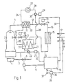
- An absorption heat pump based on ammonia / water according to FIG. 1 has an expeller 2 heated by a burner 1, into which a line 3 for rich solution opens and from which lines 4 for refrigerant vapor and 5 for poor solution depart.
- the burner is a gas or oil burner, which is fed via a fuel supply line 7 provided with a fuel valve 6, the valve 6 being controlled by an actuator 8 which is acted upon by a controller 10 via a control line 9.
- a condenser 11 is connected to line 4 for refrigerant vapor, line 4 continues as condensate line 12 to an expansion valve 14 provided with an actuator 13, to which a refrigerant line 16 leading to an evaporator 15 connects.
- the evaporator is fed by an environmental energy source, such as outside air or groundwater 17, the temperature of which can be sensed by a temperature sensor 18, which is connected to the controller 10 via a measuring line 19.
- an environmental energy source such as outside air or groundwater 17
- a temperature sensor 18 which is connected to the controller 10 via a measuring line 19.
- a refrigerant vapor line 20 leads to an absorber 21, from which the line 3 leads, which leads back to the expeller with the interposition of a solvent pump 22, which can be acted upon by an actuator 23, which is connected to the controller 10 via an actuating line 24.
- the line 5 for poor solution leads into the absorber 21 with the interposition of an expansion valve 26 controlled by an actuator 25.
- the sorption heat pump heats a consumer 27, which is a collective heating system made up of convectors or radiators, but also a floor heating system and / or a water heater. This consumer can be heated directly by the heat pump or with the interposition of a three or four-way mixing valve.
- a heating roller pump 30 controlled by a steep member 29 is inserted into a return line 28 of the consumer.
- the line 28 leads to a heat exchanger tube coil 31, which is accommodated in the interior of the absorber 21.
- a pipe 32 leads from the pipe coil 31 to a further heat exchanger pipe coil 33, which is accommodated in the interior of the condenser 11.
- the consumer supply line 34 is connected to the coil 33.
- the actuators 8, 25 and 13 are magnetic drives, the manipulated variable (stroke) of which is directly proportional to the current with which the controller 10 acts on them.
- the actuators 29 and 23 can be control transformers in connection with the pump motors, so that the pump speed is directly proportional to the manipulated variable from the controller 10. It would also be possible to drive the pumps at a constant speed and to implement the control function in such a way that a bypass valve is placed from the pump inlet to the pump outlet, the opening cross section of which is acted upon by the manipulated variable of the controller 10. Finally, it would also be conceivable to provide pumps with adjustable flow rate and to vary 'the flow rate per stroke or per revolution and let the electric drive constant.
- a setpoint generator 35 is connected to the controller 10 via a line 36.
- a setpoint adjuster 37 allows the maximum output of the heat pump, which can be given to the consumer 27, to be assigned to a specific outside temperature.
- a specific outside temperature For example, the area of the Federal Republic of Germany is divided into three climate zones, with the lowest expected outside temperature of -12 ° C according to DIN 4701 of climate zone 1, the outside temperature of -15 ° C of climate zone 2 and the outside temperature of -18 ° C Climate zone 3 is assigned. It is thus possible to assign the associated set power of the heat pump, be it 10, 20, 30 or 50 kW, to the respective climatic zone according to the climatic zone in which the heat pump or its controller is to be installed.
- the controller is adjusted via setpoint adjuster 37 so that the output of 30 kW at -15 ° C is obtained.
- setpoint adjuster 37 would be set so that the 30 kW would be emitted at an outside temperature of -18 ° C. This generally means that between an outside temperature at which heating is no longer at all. , for example 18 ° C, and the lowest possible outside temperature of the respective climate zone, outputs between zero and the maximum output of the heat pump are used.
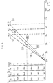
- the effect of the setting in detail can be seen from the diagram in FIG. 2:
- the lowest expected temperatures of the respective climatic zones up to a temperature at which heating is no longer recorded are plotted on the abscissa.
- the maximum outputs of the respective heat pumps are plotted on the ordinate.
- Maximum power is to be understood as the thermal power that can be given to consumers 27 at most.
- the setting is now made so that, for example in the case of a heat pump with a maximum output of 30 kW, depending on the location of the climate zone, this 30 kW either at -18 ° C according to climate zone 3 or at -15 ° C according to a location in climate zone 2 or at -12 ° C according to a location in a location of climate zone 1.
- the resulting points 40, 41 and 42 are connected to the point on the abscissa 43, beyond which it is no longer necessary to heat the living rooms with the heat pump.
- Connecting points 40, 41 and 42 on the one hand and point 43 on the other hand results in straight lines with the designations I, 11 and 111 corresponding to the respective climatic zones. This means that, for example, an actual heat pump output of 24.5 kW can be assigned to an outside temperature of -9 ° C at a location in climate zone 2, in accordance with point 44.
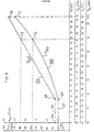
- the abscissa is the condenser pressure or, more generally, the pressure in the high-pressure part of the heat pump - in Fig. 1, the refrigerant vapor path from the expeller to the expansion valve or the path of the poor solution from the expeller to the expansion valve - together with the flow temperature of the consumer.
- the zero point is set at a condenser pressure of 10 bar, which corresponds to a room temperature and a flow temperature of 20 ° C. This is defined by point 48.
- the ordinate shows the temperatures in climate zones I, II and III, which start at zero with + 18 ° C and reach their maximum point with the end temperatures of the climate zones, i.e. -12, -15 and -18 ° C, respectively.
- the fourth standard of the ordinate is the output of the heat pump in kW.
- the zero point 48 corresponding to an outside temperature of 18 ° C, is assigned an output of 0 kW, increasing up to the nominal output of the heat pump, here 20 kW, corresponding to the lowest temperature point to be expected in the respective climate zone.
- a parameter is a low-temperature heating system in monovalent mode of operation for the heat pump, for example underfloor heating.
- Points 49, 50 and 51 result from the selection of flow temperatures of 36, 39 and 42 ° C, which are assigned to the relevant outside temperatures of the climate zone.
- the curves VII, VIII and IX thus result from a connection of one of the points 49 to 51 to the zero point 48. If such a curve is now followed by the controller 10, the scale of the abscissa automatically results from the given measured outside temperature Due to the position of the curves, a certain condenser pressure is given to the controller as the setpoint.
- the heat pump again has 20 kW and that the heat pump is installed in a location in climate zone 2.
- point VIII on curve VIII results, to which a condenser pressure of 13 bar is assigned is what also corresponds to a flow temperature of 30 ° C.
- the controller effects a flow temperature control for the setpoint of 30 ° C. If the outside temperature falls or rises, curve VIII is the controller setpoint characteristic curve, which means that the setpoint for the constant temperature to be controlled changes according to characteristic curve VIII.
- the new condenser pressure setpoint is 13.5 bar or a flow temperature of 31 ° C.
- the second family of curves X, XI and XII results if a high-temperature heating system is used as the parameter, for example a radiator heater with a flow temperature of 90 ° C and a return temperature of 70 ° C at maximum output. It can be seen that, for example, with a maximum heat pump output of 20 kW at a location in climate zone 2, the previously selected outside actual temperature of 4.8 ° C. now has a setpoint condenser pressure of 24.5 bar as point 53. This still corresponds to a target flow temperature of almost 53 ° C.
- FIG. 4 the flow temperature of a low-temperature heating system in monovalent operation is plotted as the abscissa, in the ordinate the output in kW of the selected heat pump, here again 20 kW maximum power.
- the individual climate zones 1, 2 and 3 are assigned maximum pressures of 16, 17.5 and 19 bar, each of which develops at a power of 20 kW as the maximum target pressure and which are reached at the lowest respective temperatures of the designated climate zones.
- a flow temperature of 20 ° C, corresponding to a desired room temperature of 20 ° C, is provided as the zero point 54 of the family of curves shown in FIG. 4, which is assigned to a pressure of 10 bar, regardless of the installation location and the climatic zone of the heat pump. This results in an assignment of the pressure setpoint to the heat pump output and also an assignment of both variables to the flow temperature.
- the parameter is that a high-temperature radiator system is used as the heating system, which has a flow temperature of 90 ° C and a return temperature of 70 ° C at maximum load.
- the feed is bivalent, i.e. up to a certain limit outside temperature via the heat pump, if the temperature falls below this limit by the pure boiler operation of the heat pump already mentioned at the beginning.
- the supply temperature TV in ° C is plotted on the abscissa, and the nominal power of the heat pump and the associated maximum pressures in the condenser or in the high-pressure part of the heat pump, corresponding to the installation location of the respective climate zone, are plotted on the ordinate analogously to the representation according to FIG. 4.
- the power of the heat pump is limited to 10 kW, depending on the climate zone, this corresponds to maximum condenser target pressures of 26 bar in climate zone 1, 28 bar in climate zone 2 and 30 bar in climate zone 3.
- the zero point 59 is thereby achieved that with a heating system flow temperature of 20 ° C the heat pump output is 0 kW with a condenser pressure of 10 bar.
- the maximum points 60, 61 and 62 of curves XVI to XVIII result from the fact that certain maximum flow temperatures of 55.58 and 61 ° C are assigned to the maximum output of the heat pump of 10 kW or the maximum pressure setpoint.
- the curves themselves represent the connection of one of the points 60 to 62 with the zero point 59.
- the heat pump has been selected and its maximum output according to the climate zone has been assigned to the lowest outside temperature to be expected at the installation site and the condenser target pressure is fixed, it is only necessary to have one to assign the position of the gas solenoid control valve 6 corresponding to the desired condenser pressure or the speed of the drive motor 23 for the solvent pump 22. 6 is provided to clarify this assignment. 6, the power of the heat pump up to a maximum power of 20 kW is plotted as the abscissa; this power is associated with the temperature scale in the climatic zone 2, the flow temperature TV when used on an underfloor heating and the condenser pressure P.
- This power is assigned to this power is based on a heat pump with a maximum output of 20 kW and a location in climate zone 2.
- the ordinate is the throughput of rich solution GLP in kg / h and the gas throughput to the burner VRV in m 3 / h.
- Curve XIX results for the gas throughput, curve XX for the solvent throughput. From zero point 64 and 65, both curves have a linear, constant part 66 and 67, which extends to a break point 68 and 69, respectively. In this area, the gas solenoid valve 6 or the motor of the solvent pump 23 are operated clocked in a varying pulse-pause ratio.
- Curve XX extends as a straight line from break point 68 to maximum point 70, while curve XIX has a curvature corresponding to a parabola.
- the maximum point 71 of curve XIX together with point 70 in the abscissa is the maximum output of the heat pump, here 20 kW, corresponding to the lowest temperature in the climate zone, here -15 ° C, corresponding to the maximum flow temperature, here 39 ° C, corresponding to the maximum Pressure setpoint in the high-pressure section of the heat pump, here 17.5 bar, assigned.
- the associated ordinate values result from the maximum gas throughput, which belongs to the required power of 20 kW, or the maximum solvent throughput in order to achieve this power.
- the manipulated variables of the controller are based on the gas throughput or on a corresponding voltage for the drive motor 23 of the pump 22 in order to achieve the corresponding speed of the solvent pump, from which a certain throughput follows when the delivery volume per revolution is fixed.
- the information for solvent throughput and gas throughput for other climatic zones, other end performances or other heating systems.
- V RV in m 3 / h means the gas throughput that is fed to the heat pump as a function of the desired output, which is proportional to the outside temperature or the flow temperature or the pressure in the high-pressure part of the system, as shown on the abscissa in Fig. 6.
- This gas throughput is equal to the starting gas throughput V RVmin , Fig. 6, point 69.
- This gas throughput must not be undercut, since a burner cannot be continuously regulated from maximum load to zero throughput.
- the gas throughput is initially a linearly dependent function of the power, expressed by the term A ⁇ (N - N min ).
- A is a constant with the dimension gas throughput in m 3 / h divided by power in kW.
- N min is the power at the point from which the burner is no longer controlled continuously, in our example around 4.5 kW.
- N min is the power at the point from which the burner is no longer controlled continuously, in our example around 4.5 kW.
- ⁇ V RVmin means the heat ratio at the corresponding output N min corresponding to the outside temperature according to the smallest adjustable gas throughput and ⁇ V RV all heating conditions from N min to N max according to the outside temperature at N min up to the maximum design temperature according to the temperature at N min the pressure in High pressure part at N min .
- This correction takes into account the fact that precisely because of the poorer heat ratio with a constant supply of solution, more energy has to be supplied via the gas throughput. This is because the stripping process at higher pressures in the high-pressure section and higher condensation temperatures means that more power has to be supplied in order to be able to drive out the same amount of refrigerant vapor as at lower temperatures and lower pressures in the high-pressure section.
Landscapes
- Engineering & Computer Science (AREA)
- Physics & Mathematics (AREA)
- Remote Sensing (AREA)
- General Physics & Mathematics (AREA)
- Automation & Control Theory (AREA)
- Mechanical Engineering (AREA)
- Thermal Sciences (AREA)
- General Engineering & Computer Science (AREA)
- Sorption Type Refrigeration Machines (AREA)
- Other Air-Conditioning Systems (AREA)
- Control Of Fluid Pressure (AREA)
- Control Of Temperature (AREA)
Claims (4)

Priority Applications (1)
| Application Number | Priority Date | Filing Date | Title |
|---|---|---|---|
| AT82900796T ATE9403T1 (de) | 1981-03-14 | 1982-03-12 | Verfahren zum ermitteln eines sollwertes eines temperatur- oder druckreglers einer waermepumpe. |
Applications Claiming Priority (4)
| Application Number | Priority Date | Filing Date | Title |
|---|---|---|---|
| DE8107912 | 1981-03-14 | ||
| DE8107912U | 1981-03-14 | ||
| DE8205716 | 1982-02-27 | ||
| DE8205716U | 1982-02-27 |
Publications (2)
| Publication Number | Publication Date |
|---|---|
| EP0073797A1 EP0073797A1 (fr) | 1983-03-16 |
| EP0073797B1 true EP0073797B1 (fr) | 1984-09-12 |
Family
ID=25948913
Family Applications (1)
| Application Number | Title | Priority Date | Filing Date |
|---|---|---|---|
| EP82900796A Expired EP0073797B1 (fr) | 1981-03-14 | 1982-03-12 | Procede de determination d'une valeur de consigne d'un regulateur de temperature ou de pression d'une pompe a chaleur |
Country Status (5)
| Country | Link |
|---|---|
| US (1) | US4463570A (fr) |
| EP (1) | EP0073797B1 (fr) |
| JP (1) | JPS58500377A (fr) |
| DE (1) | DE3260688D1 (fr) |
| WO (1) | WO1982003267A1 (fr) |
Families Citing this family (8)
| Publication number | Priority date | Publication date | Assignee | Title |
|---|---|---|---|---|
| US5271235A (en) * | 1991-03-12 | 1993-12-21 | Phillips Engineering Company | High efficiency absorption cycle of the gax type |
| US5367884B1 (en) * | 1991-03-12 | 1996-12-31 | Phillips Eng Co | Generator-absorber-heat exchange heat transfer apparatus and method and use thereof in a heat pump |
| US5570584A (en) * | 1991-11-18 | 1996-11-05 | Phillips Engineering Co. | Generator-Absorber heat exchange transfer apparatus and method using an intermediate liquor |
| US5579652A (en) * | 1993-06-15 | 1996-12-03 | Phillips Engineering Co. | Generator-absorber-heat exchange heat transfer apparatus and method and use thereof in a heat pump |
| US5490393A (en) * | 1994-03-31 | 1996-02-13 | Robur Corporation | Generator absorber heat exchanger for an ammonia/water absorption refrigeration system |
| US5782097A (en) * | 1994-11-23 | 1998-07-21 | Phillips Engineering Co. | Generator-absorber-heat exchange heat transfer apparatus and method and use thereof in a heat pump |
| DE10005604B4 (de) * | 2000-02-09 | 2007-06-28 | Helioplus Energy Systems Gmbh | Absorptionswärmepumpe und Verfahren zum Betrieb einer Absorptionswärmepumpe |
| EP4729855A1 (fr) * | 2024-10-18 | 2026-04-22 | Green Hac Sp. z o.o. | Procédé d'utilisation de la chaleur de sortie du fluide de travail du condenseur |
Family Cites Families (9)
| Publication number | Priority date | Publication date | Assignee | Title |
|---|---|---|---|---|
| US2850266A (en) * | 1954-10-01 | 1958-09-02 | Carrier Corp | Control system for an absorption refrigeration machine |
| US3426548A (en) * | 1967-11-13 | 1969-02-11 | Carrier Corp | Capacity control for absorption refrigeration systems |
| US3979710A (en) * | 1970-11-16 | 1976-09-07 | Danfoss A/S | Apparatus for adjusting and indicating the operating curve of a weather-responsive heating regulator |
| US4090372A (en) * | 1977-03-21 | 1978-05-23 | Jeffrey Wayne Lamb | Fuel conservation controller for capacity controlled refrigeration apparatus |
| DE2758773C2 (de) * | 1977-12-29 | 1981-12-17 | Ask August Schneider Gmbh & Co Kg, 8650 Kulmbach | Bivalente Heizanlage |
| CH635415A5 (de) * | 1978-09-13 | 1983-03-31 | Sulzer Ag | Absorptions-waermepumpenanlage. |
| DE2927408C2 (de) * | 1979-07-06 | 1984-08-09 | Ask August Schneider Gmbh & Co Kg, 8650 Kulmbach | Steuereinrichtung für eine Heizanlage mit einer Wärmepumpe |
| US4269034A (en) * | 1979-09-10 | 1981-05-26 | Rzechula Joseph A | Absorption unit with variant control system |
| DE3016251A1 (de) * | 1980-04-26 | 1981-11-05 | Linde Ag, 6200 Wiesbaden | Verfahren zur regelung einer absorptions-heizanlage |
-
1982
- 1982-03-12 US US06/438,892 patent/US4463570A/en not_active Expired - Fee Related
- 1982-03-12 JP JP57501000A patent/JPS58500377A/ja active Pending
- 1982-03-12 EP EP82900796A patent/EP0073797B1/fr not_active Expired
- 1982-03-12 WO PCT/DE1982/000060 patent/WO1982003267A1/fr not_active Ceased
- 1982-03-12 DE DE8282900796T patent/DE3260688D1/de not_active Expired
Also Published As
| Publication number | Publication date |
|---|---|
| US4463570A (en) | 1984-08-07 |
| WO1982003267A1 (fr) | 1982-09-30 |
| EP0073797A1 (fr) | 1983-03-16 |
| JPS58500377A (ja) | 1983-03-10 |
| DE3260688D1 (en) | 1984-10-18 |
Similar Documents
| Publication | Publication Date | Title |
|---|---|---|
| DE2757832C2 (de) | Kühlanlage mit geschlossenem Kältemittelkreis | |
| EP3665542B1 (fr) | Dispositif de réglage autorégulé pour une vanne de régulation de fluide, système de thermorégulation et un système de distribution comprenant celui-ci, ainsi que procédé associé | |
| EP3593055B1 (fr) | Procédé pour faire fonctionner une installation de chauffage | |
| EP0410330A2 (fr) | Procédé et dispositif de fonctionnement d'une installation frigorifique | |
| DE3109843C1 (de) | Heizungsanlage mit einem Heizkessel und einer Waermepumpe | |
| EP3443228B1 (fr) | Ensemble pompe centrifuge et procédé de réglage de son fonctionnement | |
| DE3235364C2 (de) | Warmwasser-Heizungsanlage | |
| EP3101352B1 (fr) | Procede de fonctionnement d'une installation de chauffage et dispositif de regulation comprenant un capteur de difference de pression | |
| EP2435887A2 (fr) | Ensemble à soupape | |
| WO1982003267A1 (fr) | Procede de determination d'une valeur de consigne d'un regulateur de temperature ou de pression d'une pompe a chaleur | |
| DE2710871A1 (de) | Warmwasser-umlaufheizung | |
| DE102017218139A1 (de) | Verfahren zum Betreiben einer Heizungsanlage | |
| WO2003023288A1 (fr) | Installation de chauffage central | |
| EP3779286A1 (fr) | Procédé de fonctionnement d'une installation de chauffage | |
| DE3539328A1 (de) | Verfahren zum aufheizen wenigstens zweier verbraucher | |
| EP1116921A2 (fr) | Système de conditionnement d'air d'un local pour bâtiments | |
| DE2717050A1 (de) | Kompressor-kaelteanlagen | |
| DE3606751A1 (de) | Verfahren zum ermitteln eines sollwertes | |
| DE3209703A1 (de) | Verfahren zum ermitteln eines sollwertes eines temperatur- oder druckreglers einer waermepumpe | |
| EP0107774B2 (fr) | Dispositif de régulation pour une installation de chauffage | |
| DE19735511C5 (de) | Regelverfahren für Niedertemperaturheizkessel | |
| CH627257A5 (en) | Method and device for the automatic optimisation of the operating point of a heating device, in particular of a heat pump | |
| DE2301832B2 (de) | Warmwasser-Zentralheizungssystem mit Vorlauf- und Brauchwasserthermostaten | |
| EP2652409B1 (fr) | Procédé permettant de faire fonctionner un système de pompe à chaleur | |
| DE3607159C2 (fr) |
Legal Events
| Date | Code | Title | Description |
|---|---|---|---|
| PUAI | Public reference made under article 153(3) epc to a published international application that has entered the european phase |
Free format text: ORIGINAL CODE: 0009012 |
|
| 17P | Request for examination filed |
Effective date: 19820831 |
|
| AK | Designated contracting states |
Designated state(s): AT CH DE FR GB LI LU NL SE |
|
| RAP1 | Party data changed (applicant data changed or rights of an application transferred) |
Owner name: VAILLANT GMBH Owner name: SCHONEWELLE B.V. Owner name: VAILLANT LIMITED Owner name: VAILLANT GES.M.B.H Owner name: VAILLANT S.A.R.L Owner name: JOH. VAILLANT GMBH U. CO |
|
| GRAA | (expected) grant |
Free format text: ORIGINAL CODE: 0009210 |
|
| RAP1 | Party data changed (applicant data changed or rights of an application transferred) |
Owner name: VAILLANT GMBH Owner name: SCHONEWELLE B.V. Owner name: VAILLANT LTD. Owner name: VAILLANT GES.M.B.H Owner name: VAILLANT S.A.R.L Owner name: JOH. VAILLANT GMBH U. CO |
|
| AK | Designated contracting states |
Designated state(s): AT CH DE FR GB LI LU NL SE |
|
| REF | Corresponds to: |
Ref document number: 9403 Country of ref document: AT Date of ref document: 19840915 Kind code of ref document: T |
|
| REF | Corresponds to: |
Ref document number: 3260688 Country of ref document: DE Date of ref document: 19841018 |
|
| ET | Fr: translation filed | ||
| PG25 | Lapsed in a contracting state [announced via postgrant information from national office to epo] |
Ref country code: LU Free format text: LAPSE BECAUSE OF NON-PAYMENT OF DUE FEES Effective date: 19850331 |
|
| PLBE | No opposition filed within time limit |
Free format text: ORIGINAL CODE: 0009261 |
|
| STAA | Information on the status of an ep patent application or granted ep patent |
Free format text: STATUS: NO OPPOSITION FILED WITHIN TIME LIMIT |
|
| 26N | No opposition filed | ||
| PGFP | Annual fee paid to national office [announced via postgrant information from national office to epo] |
Ref country code: AT Payment date: 19860307 Year of fee payment: 5 |
|
| PGFP | Annual fee paid to national office [announced via postgrant information from national office to epo] |
Ref country code: NL Payment date: 19860331 Year of fee payment: 5 |
|
| PGFP | Annual fee paid to national office [announced via postgrant information from national office to epo] |
Ref country code: LU Payment date: 19860411 Year of fee payment: 5 |
|
| PG25 | Lapsed in a contracting state [announced via postgrant information from national office to epo] |
Ref country code: AT Effective date: 19870312 |
|
| PG25 | Lapsed in a contracting state [announced via postgrant information from national office to epo] |
Ref country code: SE Effective date: 19870313 |
|
| PG25 | Lapsed in a contracting state [announced via postgrant information from national office to epo] |
Ref country code: LI Effective date: 19870331 Ref country code: CH Effective date: 19870331 |
|
| PG25 | Lapsed in a contracting state [announced via postgrant information from national office to epo] |
Ref country code: NL Effective date: 19871001 |
|
| NLV4 | Nl: lapsed or anulled due to non-payment of the annual fee | ||
| GBPC | Gb: european patent ceased through non-payment of renewal fee | ||
| PG25 | Lapsed in a contracting state [announced via postgrant information from national office to epo] |
Ref country code: FR Free format text: LAPSE BECAUSE OF NON-PAYMENT OF DUE FEES Effective date: 19871130 |
|
| REG | Reference to a national code |
Ref country code: CH Ref legal event code: PL |
|
| REG | Reference to a national code |
Ref country code: FR Ref legal event code: ST |
|
| PG25 | Lapsed in a contracting state [announced via postgrant information from national office to epo] |
Ref country code: GB Effective date: 19881121 |
|
| PG25 | Lapsed in a contracting state [announced via postgrant information from national office to epo] |
Ref country code: DE Effective date: 19881201 |
|
| EUG | Se: european patent has lapsed |
Ref document number: 82900796.2 Effective date: 19880215 |