EP0073836A1 - Serres accumulant la chaleur latente - Google Patents
Serres accumulant la chaleur latente Download PDFInfo
- Publication number
- EP0073836A1 EP0073836A1 EP82900663A EP82900663A EP0073836A1 EP 0073836 A1 EP0073836 A1 EP 0073836A1 EP 82900663 A EP82900663 A EP 82900663A EP 82900663 A EP82900663 A EP 82900663A EP 0073836 A1 EP0073836 A1 EP 0073836A1
- Authority
- EP
- European Patent Office
- Prior art keywords
- heat
- heat accumulating
- tank
- greenhouse
- heat storage
- Prior art date
- Legal status (The legal status is an assumption and is not a legal conclusion. Google has not performed a legal analysis and makes no representation as to the accuracy of the status listed.)
- Granted
Links
Images




Classifications
-
- F—MECHANICAL ENGINEERING; LIGHTING; HEATING; WEAPONS; BLASTING
- F28—HEAT EXCHANGE IN GENERAL
- F28D—HEAT-EXCHANGE APPARATUS, NOT PROVIDED FOR IN ANOTHER SUBCLASS, IN WHICH THE HEAT-EXCHANGE MEDIA DO NOT COME INTO DIRECT CONTACT
- F28D20/00—Heat storage plants or apparatus in general; Regenerative heat-exchange apparatus not covered by groups F28D17/00 or F28D19/00
- F28D20/02—Heat storage plants or apparatus in general; Regenerative heat-exchange apparatus not covered by groups F28D17/00 or F28D19/00 using latent heat
- F28D20/023—Heat storage plants or apparatus in general; Regenerative heat-exchange apparatus not covered by groups F28D17/00 or F28D19/00 using latent heat the latent heat storage material being enclosed in granular particles or dispersed in a porous, fibrous or cellular structure
-
- F—MECHANICAL ENGINEERING; LIGHTING; HEATING; WEAPONS; BLASTING
- F24—HEATING; RANGES; VENTILATING
- F24S—SOLAR HEAT COLLECTORS; SOLAR HEAT SYSTEMS
- F24S60/00—Arrangements for storing heat collected by solar heat collectors
- F24S60/10—Arrangements for storing heat collected by solar heat collectors using latent heat
-
- F—MECHANICAL ENGINEERING; LIGHTING; HEATING; WEAPONS; BLASTING
- F28—HEAT EXCHANGE IN GENERAL
- F28D—HEAT-EXCHANGE APPARATUS, NOT PROVIDED FOR IN ANOTHER SUBCLASS, IN WHICH THE HEAT-EXCHANGE MEDIA DO NOT COME INTO DIRECT CONTACT
- F28D20/00—Heat storage plants or apparatus in general; Regenerative heat-exchange apparatus not covered by groups F28D17/00 or F28D19/00
- F28D20/02—Heat storage plants or apparatus in general; Regenerative heat-exchange apparatus not covered by groups F28D17/00 or F28D19/00 using latent heat
-
- F—MECHANICAL ENGINEERING; LIGHTING; HEATING; WEAPONS; BLASTING
- F28—HEAT EXCHANGE IN GENERAL
- F28F—DETAILS OF HEAT-EXCHANGE AND HEAT-TRANSFER APPARATUS, OF GENERAL APPLICATION
- F28F21/00—Constructions of heat-exchange apparatus characterised by the selection of particular materials
- F28F21/06—Constructions of heat-exchange apparatus characterised by the selection of particular materials of plastics material
- F28F21/065—Constructions of heat-exchange apparatus characterised by the selection of particular materials of plastics material the heat-exchange apparatus employing plate-like or laminated conduits
-
- F—MECHANICAL ENGINEERING; LIGHTING; HEATING; WEAPONS; BLASTING
- F28—HEAT EXCHANGE IN GENERAL
- F28D—HEAT-EXCHANGE APPARATUS, NOT PROVIDED FOR IN ANOTHER SUBCLASS, IN WHICH THE HEAT-EXCHANGE MEDIA DO NOT COME INTO DIRECT CONTACT
- F28D20/00—Heat storage plants or apparatus in general; Regenerative heat-exchange apparatus not covered by groups F28D17/00 or F28D19/00
- F28D2020/0004—Particular heat storage apparatus
- F28D2020/0008—Particular heat storage apparatus the heat storage material being enclosed in plate-like or laminated elements, e.g. in plates having internal compartments
-
- F—MECHANICAL ENGINEERING; LIGHTING; HEATING; WEAPONS; BLASTING
- F28—HEAT EXCHANGE IN GENERAL
- F28D—HEAT-EXCHANGE APPARATUS, NOT PROVIDED FOR IN ANOTHER SUBCLASS, IN WHICH THE HEAT-EXCHANGE MEDIA DO NOT COME INTO DIRECT CONTACT
- F28D21/00—Heat-exchange apparatus not covered by any of the groups F28D1/00 - F28D20/00
- F28D2021/0019—Other heat exchangers for particular applications; Heat exchange systems not otherwise provided for
- F28D2021/0077—Other heat exchangers for particular applications; Heat exchange systems not otherwise provided for for tempering, e.g. with cooling or heating circuits for temperature control of elements
-
- F—MECHANICAL ENGINEERING; LIGHTING; HEATING; WEAPONS; BLASTING
- F28—HEAT EXCHANGE IN GENERAL
- F28F—DETAILS OF HEAT-EXCHANGE AND HEAT-TRANSFER APPARATUS, OF GENERAL APPLICATION
- F28F2255/00—Heat exchanger elements made of materials having special features or resulting from particular manufacturing processes
- F28F2255/02—Flexible elements
-
- Y—GENERAL TAGGING OF NEW TECHNOLOGICAL DEVELOPMENTS; GENERAL TAGGING OF CROSS-SECTIONAL TECHNOLOGIES SPANNING OVER SEVERAL SECTIONS OF THE IPC; TECHNICAL SUBJECTS COVERED BY FORMER USPC CROSS-REFERENCE ART COLLECTIONS [XRACs] AND DIGESTS
- Y02—TECHNOLOGIES OR APPLICATIONS FOR MITIGATION OR ADAPTATION AGAINST CLIMATE CHANGE
- Y02E—REDUCTION OF GREENHOUSE GAS [GHG] EMISSIONS, RELATED TO ENERGY GENERATION, TRANSMISSION OR DISTRIBUTION
- Y02E10/00—Energy generation through renewable energy sources
- Y02E10/40—Solar thermal energy, e.g. solar towers
-
- Y—GENERAL TAGGING OF NEW TECHNOLOGICAL DEVELOPMENTS; GENERAL TAGGING OF CROSS-SECTIONAL TECHNOLOGIES SPANNING OVER SEVERAL SECTIONS OF THE IPC; TECHNICAL SUBJECTS COVERED BY FORMER USPC CROSS-REFERENCE ART COLLECTIONS [XRACs] AND DIGESTS
- Y02—TECHNOLOGIES OR APPLICATIONS FOR MITIGATION OR ADAPTATION AGAINST CLIMATE CHANGE
- Y02E—REDUCTION OF GREENHOUSE GAS [GHG] EMISSIONS, RELATED TO ENERGY GENERATION, TRANSMISSION OR DISTRIBUTION
- Y02E60/00—Enabling technologies; Technologies with a potential or indirect contribution to GHG emissions mitigation
- Y02E60/14—Thermal energy storage
-
- Y—GENERAL TAGGING OF NEW TECHNOLOGICAL DEVELOPMENTS; GENERAL TAGGING OF CROSS-SECTIONAL TECHNOLOGIES SPANNING OVER SEVERAL SECTIONS OF THE IPC; TECHNICAL SUBJECTS COVERED BY FORMER USPC CROSS-REFERENCE ART COLLECTIONS [XRACs] AND DIGESTS
- Y02—TECHNOLOGIES OR APPLICATIONS FOR MITIGATION OR ADAPTATION AGAINST CLIMATE CHANGE
- Y02E—REDUCTION OF GREENHOUSE GAS [GHG] EMISSIONS, RELATED TO ENERGY GENERATION, TRANSMISSION OR DISTRIBUTION
- Y02E70/00—Other energy conversion or management systems reducing GHG emissions
- Y02E70/30—Systems combining energy storage with energy generation of non-fossil origin
Definitions
- the present invention relates to a bag-like container, and a spherical container in which a latent heat accumulating material is enclosed, and a heat accumulating apparatus employing such containers.
- the present invention generally relates to a heat accumulating material enclosing container and a heat accumulating apparatus and more particularly, to improvements of heat accumulating mat materials, latent heat accumulating greenhouses, heat accumulating medium enclosing containers, heat accumulating material capsules, solar heat accumulating greenhouses and water heaters.
- a heat accumulating mat material as a heat accumulating material enclosing bag-like container in which the rectangular flat bag-like container of a flexible material is divided or partitioned into a plurality of sections through tape-like sealing portions extending in parallel relation with respect to the longitudinal side edges and lateral side edges of said container, while a latent heat accumulating substance is enclosed in each of said divided sections, with each of said sealing portions having a width sufficient to be cut without leakage of said substance. Therefore, the size of the mat can be readily and quickly altered for installation according to the size of the heat receiving surface.
- a heat accumulating chamber partitioned by transparent sheets is provided between the attic and a floor surface facing north in the greenhouse, and a blower fan is disposed to confront an opening provided at the lower portion in said heat accumulating chamber, while, in the heat accumulating chamber, a heat accumulating unit having a large number of light transmitting windows and enclosing a phase transformation heat accumulating material therein ' is detachably suspended in a position close to window- panes at the north side.
- the arrangement is such that solar heat during shining hours is introduced into the narrow heat accumulating chamber for accumulation of heat by the use of the phase transformation heat accumulating material, and the heat thus accumulated is discharged during the period in which external atmospheric temperature has fallen.
- the high heat absorbing efficiency may be achieved through simple construction, and a large amount of endothermic heat . accumulation can be effected.
- heating by heat radiation may be continued for a long period of time, and therefore, only an extremely small amount of auxiliary heat is necessary, with a consequent saving of fuel cost to a large extent.
- a spherical main body having a through-hole, while the heat accumulating medium is enclosed in said spherical main body except for the portion for the through-hole.
- the container thus prepared is sensitive for endothermic and exothermic functions, etc., with a high heat accumulating efficiency, and may be provided at low cost through fewer faults during manufacture, as compared with conventional containers of this kind.
- the heat accumulating material capsule of the present invention a large number of heat transfer area enlarging portions are provided over the entire surface of a spherical main body, while the latent heat accumulating material is confined within the main body, with the heat transfer area enlarging portions being formed into recesses or grooves.
- the heat transfer area on the external surface of the capsule is enlarged, and the thickness of the latent heat accumulating material is reduced to provide a high heat transfer efficiency.
- the capsule since the capsule may be formed with the recesses or grooves as the heat transfer area enlarging means during molding of said spherical main body, there is no cost-wise increase involved.
- a radiator heat exchanging portion is provided at least at one side of upper or lower portion in the greenhouse, while a heat accumulating tank is disposed at a lower part in the greenhouse, with said radiator heat exchanging portion and said heat accumulating tank being connected to each other through a forced circulation liquid system.
- the heat accumulating tank as described above is made of a heat insulating tank member, in which a container enclosing the phase transformation heat accumulating medium therein is incorporated, and in said tank member, there is formed a flow passage.
- a heat collecting return pipe from a radiator heat collecting portion is connected, while, to a lower portion at the downstream side of said flow passage, a heat collecting supply pipe for said radiator heat collecting portion is coupled.
- an air discharge. pipe open towards the lower portion in the greenhouse, and an air suction pipe open towards the upper portion of the greenhouse and having an air circulating fan on the way, are connected to a latent heat accumulating tank buried in the ground within the greenhouse, in which a large number of air blast pipes extending through a cover of heat conducting material are erected in a state to be buried in the ground.
- an extremely high heat collecting efficiency is achieved so as to accumulate extra heat, which may be discharged during night time or in rainy weather, and therefore, the temperature within the greenhouse can be maintained at a required level, without employment of other heating facilities and without necessity for fuel cost, thus contributing, to a large extent, to the energy saving and saving of expenses.
- the plant culture soil is also heated simultaneously with the temperature of air within the room, growth of plants . may be expedited still further as compared with greenhouses conventionally proposed.
- spontaneous circulating flow is imparted, through employment of an anti-freezing solution as a heat medium, and in the heat accumulating tank, a container in which a latent heat accumulating material .is enclosed and a heat exchanger connected to an external water supply pipe system, are accommodated.
- a heat exchanging pipe is employed as said heat exchanger, or in the heat accumulating tank, a plurality of enclosed type hot water storage tanks are provided on the way of the heat exchanging pipe, or a relay tank equipped with a ball tap is disposed at an inlet of the heat exchanging pipe or ' an enclosed type hot water storage tank and a relay tank having a ball tap are installed for the heat exchanging pipe.
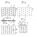
- a heat accumulating mat material according to the present invention will be explained by taking as an example, a plant culture mat to be disposed at root portions of plants within a greenhouse.
- a mat A in the form of a flat plate-like bag 1 made of a plastic film material, and the bag 1 is formed with a large number of circular holes 2 extending through the upper and lower surfaces thereof as shown. Each of the holes 2 is arranged to be of such a size as will not hinder the process of growth such as sowing, sprouting, rearing, root separation, etc. for a plant indicated at B.
- a phase transformation heat accumulating medium 3 for example, of CaCl 2 ⁇ 6H 2 O or the like is enclosed.
- CaCl 2 ⁇ 6H 2 O as described above produces reaction as follows at temperatures of 27 to 30°C. Exothermic CaC1 2 + 6H 2 0 CaCl2'6H20 Endothermic
- the mat A is directly laid on the ground surface along the undulation of the ground surface for direct sowing through the holes 2 onto the ground surface or for planting seedlings therethrough.
- the mat A subjected to solar heat during day time accumulates heat through endothermic decomposition upon rising of temperature of the hydrated compound as the heat medium up to 27 to 30°C.
- the decomposing substance . within the mat A produces heat through chemical combination so as to suppress the temperature drop within the greenhouse and the frame, and simultaneously, to prevent radiation of terrestrial heat.
- heat accumulating medium For the heat accumulating medium, following substances may be employed besides the above.
- FIG. 3 there is shown a culture mat according to a second embodiment of the present invention, which is partitioned into a check-like pattern by heat seals 4 to prevent the medium 3 within the main body A from moving in the bag.
- FIG. 4 shows a third embodiment in which the circular holes 2 in the foregoing embodiments are replaced by elongated openings 21 arranged in the parallel relation to each other.
- the plant B grows through such through-holes 2 and 21, and since said holes are each set to such a size as will not obstruct the growth of the plant, water may be absorbed into the earth during water sprinkling.
- the through-holes as described above may be in a square or elliptic shape besides the circular hole and elongated hole described as employed in the foregoing embodiments, and that the number, density and positions of the holes may be properly determined according to the kinds of plants to be cultured.
- each of the seal portions 4 1 are in the form of tapes extending in parallel relation with respect to the longitudinal side edges and lateral side edges of a rectangular flat bag-like container, and each of said seal portions 4' has a width B sufficient to be cut without leakage of the substance contained inside.
- each of the seal portions 4' may be provided with a cutting off groove along its central line in a direction of its length so as to be readily cut without any cutting tool, and also that seal portions 5 may be provided along the longitudinal side edge and/or lateral side edge to form holes 5a therein for hanging on a wall or the like, or tongue pieces 6 may be alternatively provided on such side edges.
- the mat material according to the present invention has many more applications other than the above, and, for example, may be suspended by hanging from an inner face of a north side wall of the greenhouse, or stretched across an attic of a dwelling house via suspending rods extended through the holes 2 described earlier, or stretched within a wall, etc. Furthermore, by hanging the mat material between an outer wall material and an inner wall material of a dwelling house through the holes of said mat or by holding the mat material between the inner wall material and the outer wall material, heat insulating effect for the dwelling house can be obtained.
- the greenhouse lA has a heat accumulating chamber lB provided in its interior facing the north side.
- the heat accumulating chamber 1B is partitioned by a transparent plastic sheet 101 which can be wound up except for a small gap with respect to the roof.
- At the lower portion of the heat accumulating chamber 1B there is disposed at least one blower fan 102, which confronts at least one opening 101a provided at a skirt portion of the plastic sheet 101 so as to feed air inside the heat accumulating chamber 1B into a greenhouse main portion 1A 1 through said opening 101a.
- a heat accumulating member 103 generally covering the entire area thereof is suspended in the form of a curtain.
- the heat accumulating member 103 as described above is composed of a bag-like main body 131 employing a plastic film and formed with a large number of circular windows 132 arranged in a direction of its thickness.
- the windows 132 referred to above are useful for transmitting light rays therethrough.
- the phase transformation heat accumulating medium 133 such as CaCl 2 ⁇ 6H 2 O, etc., similar to that in the previous embodiment is enclosed.
- the interior of the bag-like main body 131 is partitioned into a check-like pattern by heat seals 134 so as to be divided into many sections.
- heat seals 134 so as to be divided into many sections.
- a trough member 104 provided with a discharge pipe 104a is installed for preventing the harmful substance in the bag-like main body 131 from being diffused into the greenhouse to stay thereat, if the main body 131 should be damaged.
- the transparent plastic sheet 101 is provided in the attic inside the greenhouse, and is arranged to be freely wound up or lowered by a winch 105 to be rotated by a chain 151.
- the temperature within the greenhouse lA is raised by receiving solar heat.
- air heated up to a high temperature by direct contact with the roof is drawn into said heat accumulating chamber lB through the gap between the transparent plastic sheet 101 and the roof thereover.
- the phase transformation heat accumulating medium 133 within the heat accumulating member 103 absorbs heat to be decomposed for the heat accumulation.
- cool air deprived of heat is returned into the greenhouse main portion lA 1 through the opening at the skirt portion of the transparent plastic sheet 101.
- the heat accumulating member 103 can be readily detached, it is removed for storing during the period when heat accumulation is not necessary. Meanwhile, if the transparent plastic sheet 101 is kept wound up, the heat accumulating chamber lB may also be used as the greenhouse main portion lA i .
- the heat accumulating chamber 1B partitioned by the transparent plastic sheet 101 and capable of being subjected to air circulation is provided at the portion facing the north side in the greenhouse 1A, while, in the heat accumulating chamber, the heat accumulating member 131 in which the phase transformation heat accu- . mulating medium 133 is enclosed, is detachably suspended, air circulation between the greenhouse main portion 1A 1 and the heat accumulating chamber 1B may be effected, without obstructing the heat reception for the greenhouse main portion 1A 1 , so that the heat accumulating member 103 absorbs heat at high efficiency for the heat accumulation.
- the heat accu- . mulating member 103 has a large area, the amount of heat accumulation thereof is also large, and consequently, its duration during heat radiation is also sufficiently long.
- the heat accumulating member 103 has many light transmitting windows 132, there is no possibility that light is intercepted thereby. Additionally, the heat accumulating chamber 1B may readily be converted into the greenhouse main portion lA i , if the transparent plastic seal 101 is wound up.
- the heat accumulating effect can further be improved:
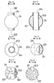
- a short tube 2A o made of a thermoplastic synthetic resin circular pipe so as to be . softened, each of the opposite ends of said tube 2A o is caused to confront a pair of pin members 2B and 2B, and the tube 2A o is deformed into a flat shape, with the pair of said pin members 2B and 2B kept in contact with the inner surface of said tube.
- the tube thus flattened is surrounded by a pair of molding split metal molds 2C and 2C each having a semi-spherical inner face or recess 2C 1 so as to hold the opposite end portions 2A 4 of the flat tube between the split metal molds 2C and 2C.
- the phase transformation heating medium 201 is charged, and thereafter, the gap at said held end portions 2A4 and the hole 2As are closed by a bonding agent to provide the heat accumulating medium enclosing container 2A as shown in Figs. 10 and 11.
- the heat accumulating medium enclosing container 2A thus formed is provided with the hole 2A3 extending through the central portion of the spherical main body 2A 1 , and also with combined projecting portions 2A 6 elongated in the width thereof along the extending direction of said through-hole 2A3, at opposite end portions of said container 2A intersecting at right angles with the through-hole 2A3.
- the gap at the held end portions 2A4 and pin member removed holes 2As remaining at opposite ends in the widthwise direction of the held end portions are filled with a bonding agent, while the heat accumulating medium 201 is enclosed in the interior of said spherical main body 2A i .
- the heat accumulating medium 201 hydrated compound producing exothermic and endothermic reactions by temperature variations, for example, CaCl 2 ⁇ 6H 2 O is employed.
- CaCl 2 ⁇ 6H 2 O as described above is raised in its temperature by radiation from a surrounding heat medium or heat conduction, and when the temperature is raised above 38°C, it becomes CaCl 2 + 6H 2 0 to produce the endothermic reaction for the heat accumulation.
- CaCl 2 and water component starts chemical reaction to give rise to the exothermic reaction.
- heat medium anti-freezing solution and the like may be employed besides air, water, etc.
- the heat medium By passing through the outer periphery and the interior of the , through-hole 2A3 of the heat accumulating medium enclosing container 2A or staying thereat, the heat medium is deprived of heat or supplied with heat as the atmospheric temperature vary and maintained at approximately a constant temperature.
- the heat accumulating medium enclosing container according to the present invention since water is passed through the interior of the through-hole 2A3, the thickness of the . container may be reduced for quick heat transfer, with a large heat transfer surface area, thus resulting in a higher heat exchanging efficiency.
- the heat accumulating medium enclosing container 2A may be so modified that the projecting portions 2A 6 including the held end portions 2A4 and pin member removed holes 2As are cut off along the spherical surface of the spherical main body 2A, so as to be formed into a spherical configuration.
- plug members 2M each having an outer diameter equal to an inner diameter of a tube material 2A o are fitted into'the central portions at upper and lower ends, while the tube material 2A 0 is surrounded, in its circular state as it is, by a pair of split metal molds 2C and 2C, and compressed air is fed into the tube material 2A o through an air pipe (not shown) extending through at least one of the plug members 2M so as to cause the tube material 2A 0 in the softened state to expand along the configuration of the inner walls within the metallic molds for molding.
- the molded item is cooled for hardening and the plug memebrs 2M are drawn out by driving hydraulic cylinders 2N, with the split metal molds 2C being opened to take out the container 2A.
- an inner tube 202 made of synthetic resin is extended through openings at the flange portions of the container 2A, and the gap between the inner faces of the flange portions and the outer face of said inner tube 202 is filled with a bonding agent.
- gas or liquid as the heating medium freely flows so as to expedite the endothermic and exothermic reactions with respect to said heat accumulating medium 201.
- projecting por- . tions 2A 7 made of the synthetic resin tube 202 and the holes at the flange portions are formed, but these projecting portions 2A 7 may be cut off along the spherical surface of the spherical main body 2A 1 as shown in Fig. 16.
- holes may be formed in the spherical surface by a drill for filling the heat accumulating medium therethrough, with plugs of synthetic resin being fused into said holes thereafter for closing.
- a capsule 3A is formed with a large number of recesses 302 over the entire surface of the spherical main body 301 as a heat transfer area enlarging means. These recesses 302 are formed in the same depth so as to be directed towards the center of the main body 301 in the embodiment, but are not necessarily limited to the center-oriented direction and the same depth.
- the main body 301 of the capsule 3A made of a high density polyethylene is enclosed therein with a latent heat accumulating material 3B such as CaCl 2 6H 2 O, etc.
- the capsule 3A is increased in its surface area, while the contact area between the heat exchanging medium such as water forming the surrounding atmosphere and the latent heat accumulating material 3B is increased, with simultaneous reduction of thickness of the heat accumulating member, and improvment of the heat transfer efficiency. Furthermore, even when some of the recesses 302 are blocked through contact thereof with neighboring capsules, remaining recesses still serve for improvement of the heat transfer efficiency.
- a plurality of rows of grooves 303 are formed in the outer periphery of the spherical main body 301 in parallel relation or in a crossed state. Similar to the previous embodiment, by the grooves 303 of such configuration also, the surface area is increased, and the improvement of heat transfer efficiency may of course be expected, with a reduction of the distance between the heat conducting surface at the bottom portions of the grooves 303 and the center of the spherical main body 301, while, even when the capsule 3A is brought into contact with a neighboring capsule, heat exchange at a high efficiency is effected at all times, since the heat exchange medium flows through the grooves 303.
- the solar heat accumulating greenhouse has a construction as follows.
- a radiator heat collecting portion 4B which includes a radiator 4B provided with fins around a water passing pipe and having an air lead-in port directed upward, and a fan 4B 2 disposed below said radiator 4B i .
- a radiator heat radiating section 4D having the construction similar to that of the radiator heat collecting portion 4B, and disposed, with an air lead-in port of a radiator 4D i directed towards the side wall of the greenhouse, and a fan 4D 2 directed towards the interior of said greenhouse.
- the tank 4C which is a latent heat accumulating tank.
- the tank 4C includes a container 401 of a synthetic resin referred to as a tank body hereinbelow) covered by a heat insulating material 404 such as expanded polystyrene or the like, a tank body cover 403 made of a corrosion-resistance metal and further applied over the outer periphery of the tank body 401 covered with the heat insulating material 404, and a plurality of cylindrical containers 409 arranged in parallel relation to each other and incorporated in said tank body 401.
- a heat insulating material 404 such as expanded polystyrene or the like
- a tank body cover 403 made of a corrosion-resistance metal and further applied over the outer periphery of the tank body 401 covered with the heat insulating material 404
- a plurality of cylindrical containers 409 arranged in parallel relation to each other and incorporated in said tank body 401.
- the phase transformation heat accumulating medium which produces exothermic and endothermic reactions through temperature radiations-is enclosed, while water is filled in the tank body 401 so as to be formed into streams.
- the interior of the tank body 401 is divided, for example, into a plurality of sections 461, 462 and 463 at its intermediate portion along long sides thereof in the horizontal direction, by a plurality of vertical partition plates 405. Meanwhile, at the upstream side and downstream side along the water streams for said sections, the uppermost stream section 407 and the lowermost stream section 408 are formed.
- the cylindrical containers 409 are arranged along the direction of the long sides of the tank body 401 to extend through the partition plates 405, with the upper and lower stages being disposed under a horizontal state in a zigzag manner so as to be fixed.
- the partition plates 405 described above are each divided into upper and lower four sheets 451, 452, 453 and 454 by holding the cylindrical containers 409 therebetween.
- the respective sections are communicated to each other by communicating pipes 410 which are open towards the lower portions of the upstream side sections through the partition walls 405, and also open towards the upper portions of the downstream side sections so as to form flow passages for producing uniform streams in the respective sections.
- a heat collecting return pipe 412 from the radiator heat collecting section 4B is connected at its upper part, while a heat radiating supply pipe 414b to the radiator heat radiating section 4D is connected at its lower portion.
- a heat collecting supply pipe 413 towards the radiator heat collecting section 4B and a heat radiating return pipe 414a from the radiator heat radiating section 4D are connected,
- each of the cylindrical containers 409 hydrated compound which produces the exothermic and endothermic reactions by temperature variations, for example, CaCl 2 ⁇ 6H 2 O is enclosed.
- CaCl 2 ⁇ 6H 2 O as referred to above becomes CaCl 2 + 6H 2 0 to produce the endothermic reaction for the heat accumulation.
- CaCl 2 and water component are subjected to chemical combination to produce the exothermic reaction, thereby to suppress lowering of water temperature within the tank.
- a heat exchanging pipe 414 made of a good heat conducting metal is disposed in a zigzag manner so as to extend through each of said sections, with the opposite ends thereof being respectively connected to said return pipe 414a and supply pipe 414b. Water to be heated is passed through the heat exchanging pipe 414.
- a heat collecting forced circulation water system 4E is connected to the heat collecting return pipe 412 and heat collecting supply pipe 413 through the radiator heat collecting section 4B described earlier, and is provided with a circulating pump 4P i at the supply pipe side.
- a heat radiating forced circulation water supply 4F is connected to the heat radiating return pipe 414a and supply pipe 414b referred to earlier through the radiator heat collecting section 4D, and in the course at the side of the supply pipe 414b, a circulating pump 4P 2 is connected.
- Part of the water pipe for the heat radiating force circulation water system 4F is buried in the ground within the greenhouse.
- the radiator heat radiating portion 4D has a high heat radiating efficiency, since it is disposed at the lower portion of the greenhouse for diffusing warm air towards the central portion, and also that part of the water piping for the heat radiation forced.
- circulating water system 4F is buried in the ground, the ground surface and the interior of the greenhouse are to be heated also from the underground.
- the heat collecting side circulating pump 4P 1 and , heat collecting section fan 4B 2 or heat radiating side circulating pump 4P 2 and heat radiating section fan 4D 2 are respectively arranged to be automatically started or stopped as in sets by the functioning of the thermostat provided within the greenhouse.
- phase transformation heat accumulating medium in the cylindrical containers 409 causes the exothermic reaction so as to prevent water temperature from falling further.
- the heat accumulating tank is capable of maintaining the temperature within said tank above the set value at all times, and has such effects that it is provided with a large thermal capacity, and can be made compact in size.
- phase transformation heat accumulating substance Na 2 SO 4 ⁇ 10H 2 O, Na 2 SO 3 ⁇ 5H 2 O, and paraffin, etc. may be employed besides the substances described earlier.
- anti-freezing solution such as ethylene glycol and the like, or fluids such as air, etc. may be employed instead of water.
- the spherical containers as described with reference to Figs. 10 through 18 or containers of any other shapes may be accommodated instead of the cylindrical containers 409.
- the heat radiating section 4D may be omitted so as to effect the heat radiating function by the heat collecting section 4B, and that, . with the heat collecting section 4B abbreviated, warm air at the ceiling portion is led to the heat radiating section 4D through a duct for effecting the heat collecting function also thereat.
- FIG. 23 there is shown the solar heat accumulating greenhouse according to another embodiment of the present invention.
- a latent heat accumulating tank 5B including a heat insulating box-like member 501 having . a corrosion-resistance surface, and a cover member 502 made, for example, of a metallic material, etc. having superior corrosion resistance and heat conduction and applied onto the upper surface of said box-like member 501, is buried in the ground within the greenhouse 5A.
- the cover member 502 is provided with a large number of blast pipes 521 extending upwardly from the cover member 502, each of which blast pipes 521 is further covered by a hood member 522 having a plurality of through-holes 522a directed in a horizontal direction as in most clearly seen in Fig. 24. Meanwhile, the cover member 502 is , provided with a plurality of shallow water discharge grooves 523 arranged in parallel relation to each other.
- the interior of the latent heat accumulating tank 5B is partitioned into a plurality of sections 5B 1 , 5B 2 , Vietnamese, and 5B n by partition members 503 of a coarse mesh- like structure.
- a large number of heat accumulating members 5S each prepared by forming a capsule, for example, capsule of a spherical shape or tetrapod-like configuration, or the spherical containers described earlier with reference to Figs. 10 through 18, or capsules of any other desired shapes with the use of a heat conducting substance, and by filling the latent heat accumulating substance in the interior thereof, are accommodated under the state where a large amount of gaps are provided therebetween.
- an air discharge pipe 504 open towards the lower portion in the greenhouse 5A and an air suction pipe 505 open at the upper central portion in the greenhouse are connected in a symmetrical relation with each other.
- an air circulating fan 506 At the lower portion on the way of said air suction pipe 505, there is provided an air circulating fan 506.
- an air collector 5C made of glass or metallic material having , sufficient solar heat absorbing ability and corrosion resistance is installed, and is connected, as a by-pass, to the upstream side suction pipe 505 along the air flow of the air circulating fan 506 described earlier.
- air plugs 505a and . 507a are respectively inserted for change-over of the air passage.
- the upper portion of the latent heat accumulating tank 5B is covered by plant culture soil 508 to such an extent as the blast pipe hoods 522 are buried therein.
- soil of coarse particles is particularly employed so that the soil may not enter the interior of the hoods via the through-holes 522a of said hoods 522.
- plants 5D are raised.
- the air valve 505a at the side of the suction pipe is opened, while the air valve 507a at the side of the air collector is closed as to form the air circulating system between the interior of the greenhouse and the latent heat accumulating tank SB, and thus, the air within the greenhouse drawn in from the air suction pipe 505 is introduced into the latent heat accumulating tank 5B for being heated, in said tank, by receiving the heat radiating action of the heat accumulating member 5S, and is dis- , charged into the greenhouse and the soil for heating in the similar manner as in the day time.
- the heat radiation into the culture soil 508 may also be effected through the heat conduction by the cover member 502.
- the water discharge grooves 523 are arranged to collect the surplus water for discharging it out of the greenhouse during irrigation.
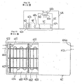
- the water heater includes a heat collecting box 601 mounted in an inclined state, and a heat accumulating tank 602 provided adjacent to the upper side in the direction of inclination of said heat collecting box.
- the heat collecting box 601 is a flat rectangular box made of steel plates and painted with black paint, in which a plurality of rows of circulating pipes 603 are accommodated in a parallel relation to each other.
- the heat accumulating tank 602 is of a cubic body made of aluminium plates and the like, and is made into a double construction having an external wall 621 and a heat insulating layer 622, with each of the rows of the circulating pipes 603 being opened into. said tank 602, while in the heat accumulating tank 602 and the circulating pipe 603, the anti-freezing solution 604 is accommodated so as to be capable of thermal expansion and heat conduction.
- a heat exchanging pipe 605 is provided in a zigzag manner for serving as a heat exchanger, which is connected to a water supply pipe system through a water supply pipe 605a, with the end of water discharge pipe being connected to a hot water supply appliance.
- the latent heat accumulating material as described above causes the exothermic or endothermic reactions to take place through temperature variations. More specifically, in the case of, for example, CaCl 2 ⁇ 6H 2 O, reaction as follows takes place at temperature of 38°C.
- the anti-freezing solution within the heat collectina box 1 raised in its temperature by receiving the solar heat is subjected to the thermal expansion and reaches the heat accumulating tank 602 through the circulating pipe 603.. Accordingly, when the temperature of the hydrated compound within the heat accumulating tank 602 is raised above 38°C through the endothermic reaction, the hydrated compound is decomposed into CaCl 2 and water.
- the anti-freezing solution is accommodated in the circulating pipe 603 and the heat accumulating tank 602, the anti-freezing solution is not freezed, even when temperature suddenly falls in cold districts during winter time, and therefore, there is no possibility that accidents such as rupture of the circulating pipe 603, etc. take place. Moreover, owing to the fact that the interior of the heat accumulating tank 602 is maintained at 38°C minimum under the ordinary state by the function of the latent heat accumulating material, a high heat accumulating efficiency may be achieved.
- FIG. 26 showing another embodiment according to the present invention in which a plurality of enclosed type hot water storage tanks 651 are provided on the way of the heat exchanging pipe 605 within the heat accumulating tank 602.
- hot water of a certain amount can be stored, and thus, hot water sufficient in amount for washing faces and hands, etc. may be heated for storage, with a favorable heat exchanging efficiency
- Fig. 27 showing a still another embodiment of.the present invention in which a relay tank 652 is provided at an inlet of the heat exchanging pipe 605 within the heat accumulating tank 602, with a ball tap 607 being provided in said relay tank.
- the ball tap 607 is opened to replenish city water, and thus, the amounts of water in the heat exchanging pipe 605 and the relay tank 652 are maintained at predetermined levels at all times.
- the constructions in the second and the third embodiments may be combined, and the enclosed type hot water storage tanks 651 are provided on the way of the heat exchanging pipe 605, with the relay tank 652 being provided at the inlet of the heat exchanging pipe 605 within the heat accumulating tank.
Landscapes
- Engineering & Computer Science (AREA)
- Physics & Mathematics (AREA)
- Thermal Sciences (AREA)
- Mechanical Engineering (AREA)
- General Engineering & Computer Science (AREA)
- Chemical & Material Sciences (AREA)
- Dispersion Chemistry (AREA)
- Life Sciences & Earth Sciences (AREA)
- Sustainable Development (AREA)
- Sustainable Energy (AREA)
- Combustion & Propulsion (AREA)
- Greenhouses (AREA)
Abstract
Applications Claiming Priority (9)
| Application Number | Priority Date | Filing Date | Title |
|---|---|---|---|
| JP1981036131U JPS57150380U (fr) | 1981-03-13 | 1981-03-13 | |
| JP37146/81 | 1981-03-13 | ||
| JP56037145A JPS57150326A (en) | 1981-03-13 | 1981-03-13 | Solar energy heat storing greenhouse |
| JP56037146A JPS57150327A (en) | 1981-03-13 | 1981-03-13 | Latent heat storing greenhouse |
| JP36131/81U | 1981-03-13 | ||
| JP9975581U JPS584968U (ja) | 1981-07-03 | 1981-07-03 | 温水器 |
| JP56133165A JPS5835390A (ja) | 1981-08-24 | 1981-08-24 | 蓄熱媒体封入容器の製造方法 |
| JP1981125525U JPS5832281U (ja) | 1981-08-24 | 1981-08-24 | 蓄熱材カプセル |
| JP56133163A JPS608418B2 (ja) | 1981-08-24 | 1981-08-24 | 太陽熱蓄熱温室 |
Related Child Applications (6)
| Application Number | Title | Priority Date | Filing Date |
|---|---|---|---|
| EP84101025A Division EP0118028B1 (fr) | 1981-08-24 | 1982-03-08 | Serres pour stocker la chaleur solaire |
| EP84101025A Division-Into EP0118028B1 (fr) | 1981-08-24 | 1982-03-08 | Serres pour stocker la chaleur solaire |
| EP84101024A Division EP0121668B1 (fr) | 1981-03-13 | 1982-03-08 | Serres pour stocker la chaleur solaire |
| EP84101024A Division-Into EP0121668B1 (fr) | 1981-03-13 | 1982-03-08 | Serres pour stocker la chaleur solaire |
| EP84101023A Division EP0118720A3 (fr) | 1981-08-24 | 1982-03-08 | Conteneur de matériau pour stocker la chaleur |
| EP84101023A Division-Into EP0118720A3 (fr) | 1981-08-24 | 1982-03-08 | Conteneur de matériau pour stocker la chaleur |
Publications (3)
| Publication Number | Publication Date |
|---|---|
| EP0073836A1 true EP0073836A1 (fr) | 1983-03-16 |
| EP0073836A4 EP0073836A4 (fr) | 1983-08-03 |
| EP0073836B1 EP0073836B1 (fr) | 1985-06-05 |
Family
ID=27564414
Family Applications (1)
| Application Number | Title | Priority Date | Filing Date |
|---|---|---|---|
| EP82900663A Expired EP0073836B1 (fr) | 1981-03-13 | 1982-03-08 | Serres accumulant la chaleur latente |
Country Status (3)
| Country | Link |
|---|---|
| EP (1) | EP0073836B1 (fr) |
| AU (3) | AU548850B2 (fr) |
| WO (1) | WO1982003271A1 (fr) |
Cited By (5)
| Publication number | Priority date | Publication date | Assignee | Title |
|---|---|---|---|---|
| EP0109043A1 (fr) * | 1982-11-13 | 1984-05-23 | Forschungszentrum Jülich Gmbh | Accumulateur de chaleur latente avec un hydrate salin ou un mélange d'hydrates salins et de sels |
| WO1996030710A1 (fr) * | 1995-03-31 | 1996-10-03 | Jean Patry | Dispositif echangeur-stockeur de calories et/ou de frigories |
| EP2011386A1 (fr) * | 2007-07-04 | 2009-01-07 | Knauf Gips Ag | Feuille pour construction, étang et piscine |
| CN103650988A (zh) * | 2013-12-25 | 2014-03-26 | 山东省农业科学院蔬菜花卉研究所 | 可变中墙双面日光温室 |
| CN103918508A (zh) * | 2014-04-17 | 2014-07-16 | 中国科学院新疆生态与地理研究所 | 一种利用太阳能的农田微气候干预系统 |
Families Citing this family (6)
| Publication number | Priority date | Publication date | Assignee | Title |
|---|---|---|---|---|
| AUPO315096A0 (en) * | 1996-10-21 | 1996-11-14 | Thermal Energy Accumulator Products Pty Ltd | A temperature control system |
| CN102613164B (zh) * | 2012-04-01 | 2014-06-04 | 常熟南师大发展研究院有限公司 | 加热法杀灭地下害虫的设备及方法 |
| NL2012650B1 (nl) * | 2014-04-17 | 2016-07-04 | Derks Innovatie & Advies B V | Ondergrondse warmte-geïsoleerde opslag en werkwijze voor het verschaffen daarvan, en constructiedeel daarvoor en gebruik van dit constructiedeel. |
| US20220217875A1 (en) * | 2019-04-05 | 2022-07-07 | Phase Change Energy Solutions, Inc. | Thermal Management Devices and Methods |
| CN110160274B (zh) * | 2019-06-03 | 2024-03-08 | 复旦大学 | 一种基于石墨烯材料的中低温储热装置 |
| CN113400532B (zh) * | 2021-05-24 | 2023-03-24 | 芜湖骏宇新材料科技有限公司 | 一种热隔膜机 |
Family Cites Families (21)
| Publication number | Priority date | Publication date | Assignee | Title |
|---|---|---|---|---|
| US2525261A (en) * | 1946-09-30 | 1950-10-10 | James P Henderson | Refrigerated ball dispenser |
| JPS396676Y1 (fr) * | 1962-06-23 | 1964-03-17 | ||
| JPS5654541B2 (fr) * | 1974-03-18 | 1981-12-26 | ||
| JPS5411011B2 (fr) * | 1974-08-01 | 1979-05-11 | ||
| JPS5127964U (fr) * | 1974-08-22 | 1976-02-28 | ||
| JPS51129742A (en) * | 1975-04-30 | 1976-11-11 | Nippon Pillar Packing | Regenerative green house heating method utilizing solar heat |
| JPS51135234A (en) * | 1975-05-12 | 1976-11-24 | Nippon Pillar Packing | Heating system for green house utilizing solar heat |
| US4024910A (en) * | 1975-05-21 | 1977-05-24 | Werner Frank D | Rock channel heat storage |
| JPS53131557A (en) * | 1977-04-21 | 1978-11-16 | Agency Of Ind Science & Technol | Regenerative tank |
| DE2729635A1 (de) * | 1977-06-30 | 1979-01-11 | Anders Daniel Backlund | Heizungs- und klimaausgleichssystem |
| JPS5491444A (en) * | 1977-12-28 | 1979-07-19 | Showa Aluminium Co Ltd | Green house |
| JPS54143459U (fr) * | 1978-03-29 | 1979-10-04 | ||
| JPS54143464U (fr) * | 1978-03-29 | 1979-10-04 | ||
| US4205656A (en) * | 1978-06-06 | 1980-06-03 | Scarlata Robert W | Thermal storage reservoirs |
| FR2428223A1 (fr) * | 1978-06-09 | 1980-01-04 | Armines | Dispositif de stockage de chaleur |
| US4287942A (en) * | 1978-06-30 | 1981-09-08 | Whitman William C | Heat storage apparatus |
| JPS5556570U (fr) * | 1978-10-13 | 1980-04-17 | ||
| JPS5584486U (fr) * | 1978-12-08 | 1980-06-11 | ||
| JPS55143455U (fr) * | 1979-03-16 | 1980-10-14 | ||
| US4421101A (en) * | 1979-10-30 | 1983-12-20 | Kalwall Corporation | Thermal energy storage system |
| JPS5714182A (en) * | 1980-06-27 | 1982-01-25 | Toshiba Corp | Heat accumulating mat |
-
1982
- 1982-03-08 EP EP82900663A patent/EP0073836B1/fr not_active Expired
- 1982-03-08 AU AU82030/82A patent/AU548850B2/en not_active Ceased
- 1982-03-08 WO PCT/JP1982/000062 patent/WO1982003271A1/fr not_active Ceased
-
1985
- 1985-10-24 AU AU49048/85A patent/AU568780B2/en not_active Ceased
- 1985-10-24 AU AU49047/85A patent/AU569181B2/en not_active Ceased
Cited By (8)
| Publication number | Priority date | Publication date | Assignee | Title |
|---|---|---|---|---|
| EP0109043A1 (fr) * | 1982-11-13 | 1984-05-23 | Forschungszentrum Jülich Gmbh | Accumulateur de chaleur latente avec un hydrate salin ou un mélange d'hydrates salins et de sels |
| WO1996030710A1 (fr) * | 1995-03-31 | 1996-10-03 | Jean Patry | Dispositif echangeur-stockeur de calories et/ou de frigories |
| FR2732453A1 (fr) * | 1995-03-31 | 1996-10-04 | Patry Jean | Dispositif echangeur-stockeur de calories et/ou de frigories |
| EP2011386A1 (fr) * | 2007-07-04 | 2009-01-07 | Knauf Gips Ag | Feuille pour construction, étang et piscine |
| EP2011387A1 (fr) * | 2007-07-04 | 2009-01-07 | Knauf Gips KG | Feuille de construction |
| CN103650988A (zh) * | 2013-12-25 | 2014-03-26 | 山东省农业科学院蔬菜花卉研究所 | 可变中墙双面日光温室 |
| CN103918508A (zh) * | 2014-04-17 | 2014-07-16 | 中国科学院新疆生态与地理研究所 | 一种利用太阳能的农田微气候干预系统 |
| CN103918508B (zh) * | 2014-04-17 | 2015-08-12 | 中国科学院新疆生态与地理研究所 | 一种利用太阳能的农田微气候干预系统 |
Also Published As
| Publication number | Publication date |
|---|---|
| AU4904785A (en) | 1986-03-13 |
| AU4904885A (en) | 1986-03-13 |
| EP0073836A4 (fr) | 1983-08-03 |
| AU568780B2 (en) | 1988-01-07 |
| WO1982003271A1 (fr) | 1982-09-30 |
| AU569181B2 (en) | 1988-01-21 |
| AU548850B2 (en) | 1986-01-02 |
| AU8203082A (en) | 1982-10-06 |
| EP0073836B1 (fr) | 1985-06-05 |
Similar Documents
| Publication | Publication Date | Title |
|---|---|---|
| US4565242A (en) | Heat accumulating material enclosing container and heat accumulating apparatus | |
| EP0073836A1 (fr) | Serres accumulant la chaleur latente | |
| US4305681A (en) | Method and apparatus for controlling the temperatures of asphalt bodies and concrete bodies | |
| US4129177A (en) | Solar heating and cooling system | |
| US4517958A (en) | Heat exchange system | |
| US4408596A (en) | Heat exchange system | |
| Al-Jamal | Greenhouse cooling in hot countries | |
| EP0377473A2 (fr) | Capsules de stockage de la chaleur latente contenant une composition pour stocker la chaleur et appareil de contrôle de la température utilisant lesdites capsules | |
| KR100400435B1 (ko) | 이중 진공관형 태양열 집열기의 열팽창 흡수장치 | |
| US4510921A (en) | Latent heat accumulating greenhouse | |
| CN210537763U (zh) | 组装式框架全相变材料日光温室 | |
| US4380993A (en) | Combined solar collector and storage pond | |
| US4446853A (en) | Solar collector panel | |
| US4271824A (en) | Solar heating apparatus | |
| US4211209A (en) | Method and apparatus for collecting and domestic use of solar heat | |
| EP0118028B1 (fr) | Serres pour stocker la chaleur solaire | |
| CN207531479U (zh) | 一种新型冬暖式大棚 | |
| JPS5849853A (ja) | 蓄熱装置 | |
| JPS6142036Y2 (fr) | ||
| JPS6320913Y2 (fr) | ||
| KR880000956B1 (ko) | 태양열 축열온실 | |
| EP0051333A1 (fr) | Dispositif pour l'absorption de chaleur solaire | |
| JPS5920599Y2 (ja) | 蓄熱壁体 | |
| CA1108879A (fr) | Systeme de chauffage a heliocapteur et stockage enfoui | |
| JPS5845439A (ja) | 太陽熱温水装置 |
Legal Events
| Date | Code | Title | Description |
|---|---|---|---|
| PUAI | Public reference made under article 153(3) epc to a published international application that has entered the european phase |
Free format text: ORIGINAL CODE: 0009012 |
|
| 17P | Request for examination filed |
Effective date: 19821108 |
|
| AK | Designated contracting states |
Designated state(s): DE FR GB NL SE |
|
| RIN1 | Information on inventor provided before grant (corrected) |
Inventor name: TANAKA, SHIGERU Inventor name: ITO, HAJIME Inventor name: MAKITO, ISAO Inventor name: YANO, NAOMICHI |
|
| GRAA | (expected) grant |
Free format text: ORIGINAL CODE: 0009210 |
|
| AK | Designated contracting states |
Designated state(s): DE FR GB NL SE |
|
| REF | Corresponds to: |
Ref document number: 3263995 Country of ref document: DE Date of ref document: 19850711 |
|
| ET | Fr: translation filed | ||
| PLBE | No opposition filed within time limit |
Free format text: ORIGINAL CODE: 0009261 |
|
| STAA | Information on the status of an ep patent application or granted ep patent |
Free format text: STATUS: NO OPPOSITION FILED WITHIN TIME LIMIT |
|
| 26N | No opposition filed | ||
| PGFP | Annual fee paid to national office [announced via postgrant information from national office to epo] |
Ref country code: SE Payment date: 19890310 Year of fee payment: 8 |
|
| PGFP | Annual fee paid to national office [announced via postgrant information from national office to epo] |
Ref country code: DE Payment date: 19890314 Year of fee payment: 8 |
|
| PGFP | Annual fee paid to national office [announced via postgrant information from national office to epo] |
Ref country code: FR Payment date: 19890320 Year of fee payment: 8 |
|
| PGFP | Annual fee paid to national office [announced via postgrant information from national office to epo] |
Ref country code: NL Payment date: 19890331 Year of fee payment: 8 Ref country code: GB Payment date: 19890331 Year of fee payment: 8 |
|
| PG25 | Lapsed in a contracting state [announced via postgrant information from national office to epo] |
Ref country code: GB Effective date: 19900308 |
|
| PG25 | Lapsed in a contracting state [announced via postgrant information from national office to epo] |
Ref country code: SE Effective date: 19900309 |
|
| PG25 | Lapsed in a contracting state [announced via postgrant information from national office to epo] |
Ref country code: NL Effective date: 19901001 |
|
| GBPC | Gb: european patent ceased through non-payment of renewal fee | ||
| NLV4 | Nl: lapsed or anulled due to non-payment of the annual fee | ||
| PG25 | Lapsed in a contracting state [announced via postgrant information from national office to epo] |
Ref country code: FR Effective date: 19901130 |
|
| PG25 | Lapsed in a contracting state [announced via postgrant information from national office to epo] |
Ref country code: DE Effective date: 19901201 |
|
| REG | Reference to a national code |
Ref country code: FR Ref legal event code: ST |
|
| EUG | Se: european patent has lapsed |
Ref document number: 82900663.4 Effective date: 19910110 |