EP0073836B1 - Gewächshäuser mit Latentwärmespeicherung - Google Patents
Gewächshäuser mit Latentwärmespeicherung Download PDFInfo
- Publication number
- EP0073836B1 EP0073836B1 EP82900663A EP82900663A EP0073836B1 EP 0073836 B1 EP0073836 B1 EP 0073836B1 EP 82900663 A EP82900663 A EP 82900663A EP 82900663 A EP82900663 A EP 82900663A EP 0073836 B1 EP0073836 B1 EP 0073836B1
- Authority
- EP
- European Patent Office
- Prior art keywords
- heat accumulating
- greenhouse
- latent heat
- heat
- chamber
- Prior art date
- Legal status (The legal status is an assumption and is not a legal conclusion. Google has not performed a legal analysis and makes no representation as to the accuracy of the status listed.)
- Expired
Links
- 239000000463 material Substances 0.000 claims description 11
- 239000000126 substance Substances 0.000 claims description 8
- 238000009825 accumulation Methods 0.000 claims description 7
- 230000009466 transformation Effects 0.000 claims description 7
- 238000007789 sealing Methods 0.000 claims description 4
- 239000002985 plastic film Substances 0.000 description 9
- 229920003023 plastic Polymers 0.000 description 7
- 238000010438 heat treatment Methods 0.000 description 5
- 230000005855 radiation Effects 0.000 description 4
- 230000000694 effects Effects 0.000 description 2
- 238000010276 construction Methods 0.000 description 1
- 238000009792 diffusion process Methods 0.000 description 1
- 239000000446 fuel Substances 0.000 description 1
- 238000009434 installation Methods 0.000 description 1
- 238000004519 manufacturing process Methods 0.000 description 1
- 238000005192 partition Methods 0.000 description 1
- 229920006255 plastic film Polymers 0.000 description 1
- XLYOFNOQVPJJNP-UHFFFAOYSA-N water Substances O XLYOFNOQVPJJNP-UHFFFAOYSA-N 0.000 description 1
Images
Classifications
-
- F—MECHANICAL ENGINEERING; LIGHTING; HEATING; WEAPONS; BLASTING
- F28—HEAT EXCHANGE IN GENERAL
- F28D—HEAT-EXCHANGE APPARATUS, NOT PROVIDED FOR IN ANOTHER SUBCLASS, IN WHICH THE HEAT-EXCHANGE MEDIA DO NOT COME INTO DIRECT CONTACT
- F28D20/00—Heat storage plants or apparatus in general; Regenerative heat-exchange apparatus not covered by groups F28D17/00 or F28D19/00
- F28D20/02—Heat storage plants or apparatus in general; Regenerative heat-exchange apparatus not covered by groups F28D17/00 or F28D19/00 using latent heat
- F28D20/023—Heat storage plants or apparatus in general; Regenerative heat-exchange apparatus not covered by groups F28D17/00 or F28D19/00 using latent heat the latent heat storage material being enclosed in granular particles or dispersed in a porous, fibrous or cellular structure
-
- F—MECHANICAL ENGINEERING; LIGHTING; HEATING; WEAPONS; BLASTING
- F24—HEATING; RANGES; VENTILATING
- F24S—SOLAR HEAT COLLECTORS; SOLAR HEAT SYSTEMS
- F24S60/00—Arrangements for storing heat collected by solar heat collectors
- F24S60/10—Arrangements for storing heat collected by solar heat collectors using latent heat
-
- F—MECHANICAL ENGINEERING; LIGHTING; HEATING; WEAPONS; BLASTING
- F28—HEAT EXCHANGE IN GENERAL
- F28D—HEAT-EXCHANGE APPARATUS, NOT PROVIDED FOR IN ANOTHER SUBCLASS, IN WHICH THE HEAT-EXCHANGE MEDIA DO NOT COME INTO DIRECT CONTACT
- F28D20/00—Heat storage plants or apparatus in general; Regenerative heat-exchange apparatus not covered by groups F28D17/00 or F28D19/00
- F28D20/02—Heat storage plants or apparatus in general; Regenerative heat-exchange apparatus not covered by groups F28D17/00 or F28D19/00 using latent heat
-
- F—MECHANICAL ENGINEERING; LIGHTING; HEATING; WEAPONS; BLASTING
- F28—HEAT EXCHANGE IN GENERAL
- F28F—DETAILS OF HEAT-EXCHANGE AND HEAT-TRANSFER APPARATUS, OF GENERAL APPLICATION
- F28F21/00—Constructions of heat-exchange apparatus characterised by the selection of particular materials
- F28F21/06—Constructions of heat-exchange apparatus characterised by the selection of particular materials of plastics material
- F28F21/065—Constructions of heat-exchange apparatus characterised by the selection of particular materials of plastics material the heat-exchange apparatus employing plate-like or laminated conduits
-
- F—MECHANICAL ENGINEERING; LIGHTING; HEATING; WEAPONS; BLASTING
- F28—HEAT EXCHANGE IN GENERAL
- F28D—HEAT-EXCHANGE APPARATUS, NOT PROVIDED FOR IN ANOTHER SUBCLASS, IN WHICH THE HEAT-EXCHANGE MEDIA DO NOT COME INTO DIRECT CONTACT
- F28D20/00—Heat storage plants or apparatus in general; Regenerative heat-exchange apparatus not covered by groups F28D17/00 or F28D19/00
- F28D2020/0004—Particular heat storage apparatus
- F28D2020/0008—Particular heat storage apparatus the heat storage material being enclosed in plate-like or laminated elements, e.g. in plates having internal compartments
-
- F—MECHANICAL ENGINEERING; LIGHTING; HEATING; WEAPONS; BLASTING
- F28—HEAT EXCHANGE IN GENERAL
- F28D—HEAT-EXCHANGE APPARATUS, NOT PROVIDED FOR IN ANOTHER SUBCLASS, IN WHICH THE HEAT-EXCHANGE MEDIA DO NOT COME INTO DIRECT CONTACT
- F28D21/00—Heat-exchange apparatus not covered by any of the groups F28D1/00 - F28D20/00
- F28D2021/0019—Other heat exchangers for particular applications; Heat exchange systems not otherwise provided for
- F28D2021/0077—Other heat exchangers for particular applications; Heat exchange systems not otherwise provided for for tempering, e.g. with cooling or heating circuits for temperature control of elements
-
- F—MECHANICAL ENGINEERING; LIGHTING; HEATING; WEAPONS; BLASTING
- F28—HEAT EXCHANGE IN GENERAL
- F28F—DETAILS OF HEAT-EXCHANGE AND HEAT-TRANSFER APPARATUS, OF GENERAL APPLICATION
- F28F2255/00—Heat exchanger elements made of materials having special features or resulting from particular manufacturing processes
- F28F2255/02—Flexible elements
-
- Y—GENERAL TAGGING OF NEW TECHNOLOGICAL DEVELOPMENTS; GENERAL TAGGING OF CROSS-SECTIONAL TECHNOLOGIES SPANNING OVER SEVERAL SECTIONS OF THE IPC; TECHNICAL SUBJECTS COVERED BY FORMER USPC CROSS-REFERENCE ART COLLECTIONS [XRACs] AND DIGESTS
- Y02—TECHNOLOGIES OR APPLICATIONS FOR MITIGATION OR ADAPTATION AGAINST CLIMATE CHANGE
- Y02E—REDUCTION OF GREENHOUSE GAS [GHG] EMISSIONS, RELATED TO ENERGY GENERATION, TRANSMISSION OR DISTRIBUTION
- Y02E10/00—Energy generation through renewable energy sources
- Y02E10/40—Solar thermal energy, e.g. solar towers
-
- Y—GENERAL TAGGING OF NEW TECHNOLOGICAL DEVELOPMENTS; GENERAL TAGGING OF CROSS-SECTIONAL TECHNOLOGIES SPANNING OVER SEVERAL SECTIONS OF THE IPC; TECHNICAL SUBJECTS COVERED BY FORMER USPC CROSS-REFERENCE ART COLLECTIONS [XRACs] AND DIGESTS
- Y02—TECHNOLOGIES OR APPLICATIONS FOR MITIGATION OR ADAPTATION AGAINST CLIMATE CHANGE
- Y02E—REDUCTION OF GREENHOUSE GAS [GHG] EMISSIONS, RELATED TO ENERGY GENERATION, TRANSMISSION OR DISTRIBUTION
- Y02E60/00—Enabling technologies; Technologies with a potential or indirect contribution to GHG emissions mitigation
- Y02E60/14—Thermal energy storage
-
- Y—GENERAL TAGGING OF NEW TECHNOLOGICAL DEVELOPMENTS; GENERAL TAGGING OF CROSS-SECTIONAL TECHNOLOGIES SPANNING OVER SEVERAL SECTIONS OF THE IPC; TECHNICAL SUBJECTS COVERED BY FORMER USPC CROSS-REFERENCE ART COLLECTIONS [XRACs] AND DIGESTS
- Y02—TECHNOLOGIES OR APPLICATIONS FOR MITIGATION OR ADAPTATION AGAINST CLIMATE CHANGE
- Y02E—REDUCTION OF GREENHOUSE GAS [GHG] EMISSIONS, RELATED TO ENERGY GENERATION, TRANSMISSION OR DISTRIBUTION
- Y02E70/00—Other energy conversion or management systems reducing GHG emissions
- Y02E70/30—Systems combining energy storage with energy generation of non-fossil origin
Definitions
- This invention relates to latent heat accumulating greenhouses.
- JP-A-51-129742 and JP-A-51-135234 disclose a greenhouse solar heating system in which a plurality of heat accumulating elements enclosing latent heat accumulating material are disposed at the position through which the sun's rays pass into the greenhouse, and air circulating means such as fan is provided.
- the heat accumulating elements are costly to manufacture, require a large scale mounting means and can not be attached or detached easily.
- a latent heat accumulating greenhouse including a heat accumulating member enclosing latent heat accumulating material therein and disposed at a position where the sun's rays pass into the greenhouse, and a fan for effecting air circulation within the greenhouse; characterised in that a heat accumulating chamber is provided in the greenhouse partitioned by a transparent sheet from the remainder of the interior of the greenhouse between an attic and a floor surface and facing north; in that the fan is a blower fan disposed to confront an opening in the lower part of the heat accumulating chamber; in that the heat accumulating member is in the heat accumulation chamber, has a large number of light transmitting windows and encloses therein the latent heat accumulating material which is a phase transformation heat accumulating material; and in that the heat accumulating member is detachably suspended in a position close to windows at the north side of the greenhouse.
- the arrangement is such that solar heat during sun shining hours is introduced into the heat accumulating chamber, which can be made narrow, for accumulation of heat by the use of the phase transformation heat accumulating material, and the heat thus accumulated is discharged during the period in which external atmospheric temperature has fallen.
- high heat absorbing efficiency may be achieved with a simple construction, and a large amount of endothermic heat accumulation can be effected.
- heating by heat radiation may be continued for a long period of time, and therefore, only an extremely small amount of auxiliary heat is necessary, with a consequent saving of fuel cost.
- the heat accumulating member comprises a rectangular flat bag-like container of flexible material which is divided into a plurality of sections by tape-like sealing portions extending in parallel relation with respect to the longitudinal side edges and lateral side edges of the container, the latent heat accumulating substance being enclosed in each of the divided sections.
- Each of the sealing portions can be of a width sufficient to be cut without leakage of the latent heat accumulating substance and thus the size of the mat can be readily and quickly altered for installation according to the size of the heat receiving surface.
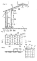
- the greenhouse 1A has a heat accumulating chamber 1B provided in its interior facing the north side.
- the heat accumulating chamber 1B is partitioned from the remainder of the interior of the greenhouse by a transparent plastic sheet 101 which can be wound up except for a small gap with respect to the roof.
- At the lower portion of the heat accumulating chamber 1B there is disposed at least one blower fan 102, which confronts at least one opening 101a provided in a skirt portion of the plastic sheet 101 so as to feed air from inside the heat accumulating chamber 1B into a greenhouse main portion 1A1, through the opening 101a.
- a heat accumulating member 103 in the form of a curtain is suspended so as to cover generally the entire area of the window panes.
- the heat accumulating member 103 is composed of a bag-like main body 131 employing a plastic film and formed with a large number of circular windows 132 arranged in the direction of its thickness.
- the windows 132 are useful for transmitting light rays therethrough.
- Phase transformation heat accumulating medium 133 such as CaCI 2 . 6H 2 0, is enclosed in the bag-like main body 131.
- the interior of the bag-like main body 131 is partitioned into a check-like pattern by heat seals 134 so as to be divided into many sections.
- heat seals 134 By providing these internal partitions, not only is the movement of the medium within the main body 131 restricted, but if the bag-like main body 131 should be broken, the amount of medium flowing out is limited to a minimum.
- tongue pieces 135 At the top edge portion of the bag-like main body 131, tongue pieces 135 having holes 135a for hanging the main body 131 are provided.
- a trough member 104 provided with a discharge pipe 104a is installed for collecting harmful substance issuing from the bag-like main body 131 should the main body be damaged. Diffusion of the substance into the greenhouse should the main body 131 be damaged is thus prevented.
- the transparent plastic sheet 101 When the transparent plastic sheet 101 is wound up it is housed in an attic inside the greenhouse. This sheet 101 can be freely wound up or lowered by a winch pulley 105 rotated by a chain 151.
- the temperature within the greenhouse 1A is raised by receiving solar heat.
- air heated up to a high temperature by direct contact with the roof is drawn into the heat accumulating chamber 1 through the gap between the transparent plastic sheet 101 and the roof thereover.
- the phase transformation heat accumulating medium 133 within the heat accumulating member 103 absorbs heat to be decomposed to accumulate heat. Cool air deprived of heat is returned into the greenhouse main portion 1A 1 through the opening(s) 101a in the skirt portion of the transparent plastic sheet 101.
- CaC1 2 decomposed within the bag-like main body 131 combines with water to produce heat for heat radiation into the heat accumulating chamber 1B.
- warm air thus produced in the heat accumulating chamber 1B is fed into the greenhouse main portion 1A i , for heating. Accordingly, during heat radiation by the phase transformation heat accumulating material 133, no other heating will normally be required. Heating by other means will be used only for short periods, for example, during very cold seasons or when rainy weather continues for a long period.
- a blower fan casing is indicated by numeral 121.
- the heat accumulating member 103 can be readily detached, it can be removed for storing during periods when heat accumulation is not necessary. During such periods, if the transparent plastic sheet 101 is kept wound up, the heat accumulating chamber 1 B may be used as an extension of the greenhouse main portion 1A i .
- the heat accumulating chamber 1 B partitioned by the transparent plastic sheet 101 and capable of being subjected to air circulation is provided at the portion facing the north side in the greenhouse 1A, and since there is detachably suspended in the heat accumulating chamber the heat accumulating member 131 in which the phase transformation heat accumulating medium 133 is enclosed, air circulation between the greenhouse main portion 1A 1 and the heat accumulating chamber 1B may be effected without obstructing heat reception for the greenhouse main portion 1A,. Therefore, the heat accumulating member 103 absorbs heat at high efficiency for heat accumulation.
- the heat accumulating member 103 has a large area, the amount of heat accumulation thereof is also large, and consequently, duration of heat emissions during heat radiation is long. Furthermore, since the heat accumulating member 103 has many light transmitting windows 132, there is no possibility that light is significantly intercepted thereby. Additionally, the heat accumulating chamber 1 B may readily be converted to be an extension of the greenhouse main portion 1A, if the transparent plastic sheet 101 is wound up.
- seal portions 4' of the heat accumulating member are in the form of tapes extending in parallel relation with respect to the longitudinal side edges and lateral side edges of a rectangular flat bag-like container. Each of these seal portions 4' has a width B sufficient to be cut without leakage of the substance contained inside. It is to be noted here that each of the seal portions 4' may be provided with a cutting-off groove along its central line in a direction of its length so as to be readily cut without any cutting tool, and also that seal portions 5 may be provided along the longitudinal top edge and/or lateral side edges with holes 5a therein for hanging the heat accumulating member on, for example, a wall. Alternatively tongue pieces 6 may be provided on this edge or these edges.
Landscapes
- Engineering & Computer Science (AREA)
- Physics & Mathematics (AREA)
- Thermal Sciences (AREA)
- Mechanical Engineering (AREA)
- General Engineering & Computer Science (AREA)
- Chemical & Material Sciences (AREA)
- Life Sciences & Earth Sciences (AREA)
- Sustainable Development (AREA)
- Sustainable Energy (AREA)
- Combustion & Propulsion (AREA)
- Dispersion Chemistry (AREA)
- Greenhouses (AREA)
Claims (3)
Applications Claiming Priority (9)
| Application Number | Priority Date | Filing Date | Title |
|---|---|---|---|
| JP1981036131U JPS57150380U (de) | 1981-03-13 | 1981-03-13 | |
| JP37146/81 | 1981-03-13 | ||
| JP56037146A JPS57150327A (en) | 1981-03-13 | 1981-03-13 | Latent heat storing greenhouse |
| JP36131/81U | 1981-03-13 | ||
| JP56037145A JPS57150326A (en) | 1981-03-13 | 1981-03-13 | Solar energy heat storing greenhouse |
| JP9975581U JPS584968U (ja) | 1981-07-03 | 1981-07-03 | 温水器 |
| JP56133163A JPS608418B2 (ja) | 1981-08-24 | 1981-08-24 | 太陽熱蓄熱温室 |
| JP56133165A JPS5835390A (ja) | 1981-08-24 | 1981-08-24 | 蓄熱媒体封入容器の製造方法 |
| JP1981125525U JPS5832281U (ja) | 1981-08-24 | 1981-08-24 | 蓄熱材カプセル |
Related Child Applications (6)
| Application Number | Title | Priority Date | Filing Date |
|---|---|---|---|
| EP84101025A Division-Into EP0118028B1 (de) | 1981-08-24 | 1982-03-08 | Treibhäuser zur Sonnenwärmespeicherung |
| EP84101025A Division EP0118028B1 (de) | 1981-08-24 | 1982-03-08 | Treibhäuser zur Sonnenwärmespeicherung |
| EP84101023A Division-Into EP0118720A3 (de) | 1981-08-24 | 1982-03-08 | Materialbehälter zur Wärmespeicherung |
| EP84101023A Division EP0118720A3 (de) | 1981-08-24 | 1982-03-08 | Materialbehälter zur Wärmespeicherung |
| EP84101024A Division-Into EP0121668B1 (de) | 1981-03-13 | 1982-03-08 | Treibhäuser zur Sonnenwärmespeicherung |
| EP84101024A Division EP0121668B1 (de) | 1981-03-13 | 1982-03-08 | Treibhäuser zur Sonnenwärmespeicherung |
Publications (3)
| Publication Number | Publication Date |
|---|---|
| EP0073836A1 EP0073836A1 (de) | 1983-03-16 |
| EP0073836A4 EP0073836A4 (de) | 1983-08-03 |
| EP0073836B1 true EP0073836B1 (de) | 1985-06-05 |
Family
ID=27564414
Family Applications (1)
| Application Number | Title | Priority Date | Filing Date |
|---|---|---|---|
| EP82900663A Expired EP0073836B1 (de) | 1981-03-13 | 1982-03-08 | Gewächshäuser mit Latentwärmespeicherung |
Country Status (3)
| Country | Link |
|---|---|
| EP (1) | EP0073836B1 (de) |
| AU (3) | AU548850B2 (de) |
| WO (1) | WO1982003271A1 (de) |
Families Citing this family (11)
| Publication number | Priority date | Publication date | Assignee | Title |
|---|---|---|---|---|
| DE3242142C2 (de) * | 1982-11-13 | 1985-06-20 | Kernforschungsanlage Jülich GmbH, 5170 Jülich | Latentwärmespeicherpackung |
| FR2732453B1 (fr) * | 1995-03-31 | 1997-05-23 | Patry Jean | Dispositif echangeur-stockeur de calories et/ou de frigories |
| AUPO315096A0 (en) * | 1996-10-21 | 1996-11-14 | Thermal Energy Accumulator Products Pty Ltd | A temperature control system |
| EP2011386A1 (de) * | 2007-07-04 | 2009-01-07 | Knauf Gips Ag | Bau-, Teich- und Schwimmbadfolie |
| CN102613164B (zh) * | 2012-04-01 | 2014-06-04 | 常熟南师大发展研究院有限公司 | 加热法杀灭地下害虫的设备及方法 |
| CN103650988A (zh) * | 2013-12-25 | 2014-03-26 | 山东省农业科学院蔬菜花卉研究所 | 可变中墙双面日光温室 |
| CN103918508B (zh) * | 2014-04-17 | 2015-08-12 | 中国科学院新疆生态与地理研究所 | 一种利用太阳能的农田微气候干预系统 |
| NL2012650B1 (nl) * | 2014-04-17 | 2016-07-04 | Derks Innovatie & Advies B V | Ondergrondse warmte-geïsoleerde opslag en werkwijze voor het verschaffen daarvan, en constructiedeel daarvoor en gebruik van dit constructiedeel. |
| WO2020206371A1 (en) * | 2019-04-05 | 2020-10-08 | Phase Change Energy Solutions, Inc. | Thermal management devices and methods |
| CN110160274B (zh) * | 2019-06-03 | 2024-03-08 | 复旦大学 | 一种基于石墨烯材料的中低温储热装置 |
| CN113400532B (zh) * | 2021-05-24 | 2023-03-24 | 芜湖骏宇新材料科技有限公司 | 一种热隔膜机 |
Citations (7)
| Publication number | Priority date | Publication date | Assignee | Title |
|---|---|---|---|---|
| JPS5127964U (de) * | 1974-08-22 | 1976-02-28 | ||
| JPS5411011B2 (de) * | 1974-08-01 | 1979-05-11 | ||
| JPS5491444A (en) * | 1977-12-28 | 1979-07-19 | Showa Aluminium Co Ltd | Green house |
| JPS5556570U (de) * | 1978-10-13 | 1980-04-17 | ||
| JPS5584486U (de) * | 1978-12-08 | 1980-06-11 | ||
| JPS5682351A (en) * | 1979-10-30 | 1981-07-06 | Kalwall Corp | Accumulator for solar energy |
| JPS5714182A (en) * | 1980-06-27 | 1982-01-25 | Toshiba Corp | Heat accumulating mat |
Family Cites Families (14)
| Publication number | Priority date | Publication date | Assignee | Title |
|---|---|---|---|---|
| US2525261A (en) * | 1946-09-30 | 1950-10-10 | James P Henderson | Refrigerated ball dispenser |
| JPS396676Y1 (de) * | 1962-06-23 | 1964-03-17 | ||
| JPS5654541B2 (de) * | 1974-03-18 | 1981-12-26 | ||
| JPS51129742A (en) * | 1975-04-30 | 1976-11-11 | Nippon Pillar Packing | Regenerative green house heating method utilizing solar heat |
| JPS51135234A (en) * | 1975-05-12 | 1976-11-24 | Nippon Pillar Packing | Heating system for green house utilizing solar heat |
| US4024910A (en) * | 1975-05-21 | 1977-05-24 | Werner Frank D | Rock channel heat storage |
| JPS53131557A (en) * | 1977-04-21 | 1978-11-16 | Agency Of Ind Science & Technol | Regenerative tank |
| DE2729635A1 (de) * | 1977-06-30 | 1979-01-11 | Anders Daniel Backlund | Heizungs- und klimaausgleichssystem |
| JPS54143464U (de) * | 1978-03-29 | 1979-10-04 | ||
| JPS54143459U (de) * | 1978-03-29 | 1979-10-04 | ||
| US4205656A (en) * | 1978-06-06 | 1980-06-03 | Scarlata Robert W | Thermal storage reservoirs |
| FR2428223A1 (fr) * | 1978-06-09 | 1980-01-04 | Armines | Dispositif de stockage de chaleur |
| US4287942A (en) * | 1978-06-30 | 1981-09-08 | Whitman William C | Heat storage apparatus |
| JPS55143455U (de) * | 1979-03-16 | 1980-10-14 |
-
1982
- 1982-03-08 AU AU82030/82A patent/AU548850B2/en not_active Ceased
- 1982-03-08 WO PCT/JP1982/000062 patent/WO1982003271A1/ja not_active Ceased
- 1982-03-08 EP EP82900663A patent/EP0073836B1/de not_active Expired
-
1985
- 1985-10-24 AU AU49047/85A patent/AU569181B2/en not_active Ceased
- 1985-10-24 AU AU49048/85A patent/AU568780B2/en not_active Ceased
Patent Citations (7)
| Publication number | Priority date | Publication date | Assignee | Title |
|---|---|---|---|---|
| JPS5411011B2 (de) * | 1974-08-01 | 1979-05-11 | ||
| JPS5127964U (de) * | 1974-08-22 | 1976-02-28 | ||
| JPS5491444A (en) * | 1977-12-28 | 1979-07-19 | Showa Aluminium Co Ltd | Green house |
| JPS5556570U (de) * | 1978-10-13 | 1980-04-17 | ||
| JPS5584486U (de) * | 1978-12-08 | 1980-06-11 | ||
| JPS5682351A (en) * | 1979-10-30 | 1981-07-06 | Kalwall Corp | Accumulator for solar energy |
| JPS5714182A (en) * | 1980-06-27 | 1982-01-25 | Toshiba Corp | Heat accumulating mat |
Also Published As
| Publication number | Publication date |
|---|---|
| AU548850B2 (en) | 1986-01-02 |
| EP0073836A4 (de) | 1983-08-03 |
| AU569181B2 (en) | 1988-01-21 |
| AU8203082A (en) | 1982-10-06 |
| AU568780B2 (en) | 1988-01-07 |
| AU4904785A (en) | 1986-03-13 |
| AU4904885A (en) | 1986-03-13 |
| EP0073836A1 (de) | 1983-03-16 |
| WO1982003271A1 (fr) | 1982-09-30 |
Similar Documents
| Publication | Publication Date | Title |
|---|---|---|
| US4510921A (en) | Latent heat accumulating greenhouse | |
| US4108373A (en) | Method and an installation for the air-conditioning of greenhouses and frames | |
| US4098262A (en) | Heating apparatus using solar energy | |
| SU841606A3 (ru) | Устройство дл вентил цииздАНи | |
| US4219008A (en) | Method and apparatus for solar heating and shading | |
| US4291673A (en) | Passive solar roof ice melter | |
| US4262656A (en) | Solar climate control for greenhouses | |
| US4699316A (en) | Energy efficient heating system for greenhouses | |
| KR880000957B1 (ko) | 태양열 축열온실 | |
| US4215672A (en) | Method and an installation for the air-conditioning of greenhouses and frames | |
| US4112919A (en) | Window solar heating unit | |
| CA2006971A1 (en) | Solar Window Air Heater | |
| WO1993025779A1 (en) | Ventilated ridge of a sloping glazed roof | |
| WO1993025779A9 (en) | Ventilated ridge of a sloping glazed roof | |
| EP0073836A1 (de) | Gewächshäuser mit Latentwärmespeicherung | |
| US4223663A (en) | Ceiling mounted solar heat collector | |
| MXPA06000435A (es) | Una division y metodo para controlar la temperatura en un area. | |
| KR880000955B1 (ko) | 잠열 축열 온실 | |
| US4342307A (en) | Solar collector for heating air | |
| US4285331A (en) | Solar heater | |
| KR200319112Y1 (ko) | 열차단 및 통풍이 가능한 그늘막 | |
| US4966129A (en) | Window insulating device | |
| EP0051333A1 (de) | Einrichtung zur Absorption von Sonnenwärme | |
| JPS5849853A (ja) | 蓄熱装置 | |
| EP0103342A2 (de) | Kulturgefäss von Metall |
Legal Events
| Date | Code | Title | Description |
|---|---|---|---|
| PUAI | Public reference made under article 153(3) epc to a published international application that has entered the european phase |
Free format text: ORIGINAL CODE: 0009012 |
|
| 17P | Request for examination filed |
Effective date: 19821108 |
|
| AK | Designated contracting states |
Designated state(s): DE FR GB NL SE |
|
| RIN1 | Information on inventor provided before grant (corrected) |
Inventor name: TANAKA, SHIGERU Inventor name: ITO, HAJIME Inventor name: MAKITO, ISAO Inventor name: YANO, NAOMICHI |
|
| GRAA | (expected) grant |
Free format text: ORIGINAL CODE: 0009210 |
|
| AK | Designated contracting states |
Designated state(s): DE FR GB NL SE |
|
| REF | Corresponds to: |
Ref document number: 3263995 Country of ref document: DE Date of ref document: 19850711 |
|
| ET | Fr: translation filed | ||
| PLBE | No opposition filed within time limit |
Free format text: ORIGINAL CODE: 0009261 |
|
| STAA | Information on the status of an ep patent application or granted ep patent |
Free format text: STATUS: NO OPPOSITION FILED WITHIN TIME LIMIT |
|
| 26N | No opposition filed | ||
| PGFP | Annual fee paid to national office [announced via postgrant information from national office to epo] |
Ref country code: SE Payment date: 19890310 Year of fee payment: 8 |
|
| PGFP | Annual fee paid to national office [announced via postgrant information from national office to epo] |
Ref country code: DE Payment date: 19890314 Year of fee payment: 8 |
|
| PGFP | Annual fee paid to national office [announced via postgrant information from national office to epo] |
Ref country code: FR Payment date: 19890320 Year of fee payment: 8 |
|
| PGFP | Annual fee paid to national office [announced via postgrant information from national office to epo] |
Ref country code: NL Payment date: 19890331 Year of fee payment: 8 Ref country code: GB Payment date: 19890331 Year of fee payment: 8 |
|
| PG25 | Lapsed in a contracting state [announced via postgrant information from national office to epo] |
Ref country code: GB Effective date: 19900308 |
|
| PG25 | Lapsed in a contracting state [announced via postgrant information from national office to epo] |
Ref country code: SE Effective date: 19900309 |
|
| PG25 | Lapsed in a contracting state [announced via postgrant information from national office to epo] |
Ref country code: NL Effective date: 19901001 |
|
| GBPC | Gb: european patent ceased through non-payment of renewal fee | ||
| NLV4 | Nl: lapsed or anulled due to non-payment of the annual fee | ||
| PG25 | Lapsed in a contracting state [announced via postgrant information from national office to epo] |
Ref country code: FR Effective date: 19901130 |
|
| PG25 | Lapsed in a contracting state [announced via postgrant information from national office to epo] |
Ref country code: DE Effective date: 19901201 |
|
| REG | Reference to a national code |
Ref country code: FR Ref legal event code: ST |
|
| EUG | Se: european patent has lapsed |
Ref document number: 82900663.4 Effective date: 19910110 |