EP0073852A2 - Rasoir mécanique - Google Patents
Rasoir mécanique Download PDFInfo
- Publication number
- EP0073852A2 EP0073852A2 EP81109395A EP81109395A EP0073852A2 EP 0073852 A2 EP0073852 A2 EP 0073852A2 EP 81109395 A EP81109395 A EP 81109395A EP 81109395 A EP81109395 A EP 81109395A EP 0073852 A2 EP0073852 A2 EP 0073852A2
- Authority
- EP
- European Patent Office
- Prior art keywords
- blade
- exp
- cutting edge
- exposure
- inch
- Prior art date
- Legal status (The legal status is an assumption and is not a legal conclusion. Google has not performed a legal analysis and makes no representation as to the accuracy of the status listed.)
- Granted
Links
Images



Classifications
-
- B—PERFORMING OPERATIONS; TRANSPORTING
- B26—HAND CUTTING TOOLS; CUTTING; SEVERING
- B26B—HAND-HELD CUTTING TOOLS NOT OTHERWISE PROVIDED FOR
- B26B21/00—Razors of the open or knife type; Safety razors or other shaving implements of the planing type; Hair-trimming devices involving a razor-blade; Equipment therefor
- B26B21/08—Razors of the open or knife type; Safety razors or other shaving implements of the planing type; Hair-trimming devices involving a razor-blade; Equipment therefor involving changeable blades
- B26B21/14—Safety razors with one or more blades arranged transversely to the handle
-
- B—PERFORMING OPERATIONS; TRANSPORTING
- B26—HAND CUTTING TOOLS; CUTTING; SEVERING
- B26B—HAND-HELD CUTTING TOOLS NOT OTHERWISE PROVIDED FOR
- B26B21/00—Razors of the open or knife type; Safety razors or other shaving implements of the planing type; Hair-trimming devices involving a razor-blade; Equipment therefor
- B26B21/08—Razors of the open or knife type; Safety razors or other shaving implements of the planing type; Hair-trimming devices involving a razor-blade; Equipment therefor involving changeable blades
- B26B21/14—Safety razors with one or more blades arranged transversely to the handle
- B26B21/22—Safety razors with one or more blades arranged transversely to the handle involving several blades to be used simultaneously
- B26B21/222—Safety razors with one or more blades arranged transversely to the handle involving several blades to be used simultaneously with the blades moulded into, or attached to, a changeable unit
Definitions
- the invention relates to wet shaving implements and is directed more particularly to a wet shaving implement in which there is a pluralitiy of blades.
- plastic shaving heads having blades fixed therein include US-A-3,703,764, US-A-3,724,070, and US-A-4,026,016. While such recent examples have been eminently successful, there is, as always, a need for such products which are less expensive to manufacture and offer improved functional characteristics.
- US-A-3,786,563 discloses geometrical relationships present in plural cutting edge systems. Among the important parameters of plural edge systems are "blade tangent angle”, “exposure”, and "span”.
- Such a shaving system includes two cutting edges disposed parallel to one another and in spaced relation to provide leading and following cutting edges so that both cutting edges are successively active with respect to the hair elements being cut during a single shaving stroke.
- the cutting edges are supported in spaced parallel relation to one another.
- a guard structure is disposed in fixed relation to the cutting edges to define in part the desired geometrical relationship.
- Significant components of the geometrical relationship include the above referred to "blade tangent angle", "exposure”, and "span”.
- “Blade tangent angle” is defined as the angle between the bisector of the included angle of a cutting edge and a line from the cutting edge tangent to the skin engaging surface immediately forward of that cutting edge.
- “Exposure” is defined as the distance from a cutting edge to a plane defined by skin engaging surfaces immediately in front of and behind the cutting edge the distance being measured perpendicularly to the reference plane, the exposure being considered positive when the cutting edge is located on the outer (skin) side of that plane and being considered negative when the cutting edge is further from the skin than that plane.
- “Span” is defined as the distance between the cutting edge and the skin engaging surface forward of that cutting edge.
- a further object of the invention is to provide such a system in which a plurality of cutting edges are fixed in a position with respect to one another and with respect to a cooperating guard structure and cap structure to define a desired geometrical relationship between various components of the system.
- a still further object is to provide such a shaving system in which at least one of the parameter-determing surfaces is in effect two surfaces alternating in presentation and therefore presenting alternating geometries.
- a feature of the present invention is the provision" of a shaving implement comprising a platform member, a cap member, and blade means disposed therebetween, said platform member comprising a blade support portion, a guard portion mounted forwardly of said blade support portion, and a back portion upstanding from said blade support portion, said guard and back portions defining parallel opposite lengthwise edges of said platform member, said cap member comprising a series of fingers extending from said back portion forwardly toward said guard portion, said fingers being separated from each other by recesses therebetween, said fingers including a first skinengaging point and said recesses being defined in part by a cap member wall comprising a second skin-engaging point, and said blade means comprising a first blade member having a first cutting edge disposed rearwardly of said guard portion, a second blade member having a second cutting edge disposed rearwardly of said first cutting edge, and spacer means for maintaining said first and second blade members in spaced parallel relationship, said first and second cutting edges each having
- an illustrative housing 2 includes a platform portion 4.
- a back portion 6 upstands from a lengthwise margin of the platform portion 4, and a cap portion 8 extends forwardly from the back portion 6 to overlie the platform portion.
- the housing further includes leg portions 10 extending forwardly from the platform portion and joining a guard portion 12 which is disposed parallel to the back portion 6.
- the housing is further provided with end walls 14, 16 interconnecting the back and guard portions at the ends of the housing.
- the cap portion 8 may comprise a series of spaced, aligned, forwardly extending fingers 18.
- the patform portion may be provided with a series of spaced, aligned recesses 20, the recesses being separated by platform rib portions 22.
- each of the fingers 18 is disposed over one of the recesses 20 and each of the rib portions 22 is in alignment with a space between two of the fingers 18.
- the entire housing is of molded plastic and is molded as an integral unit.
- the fingers 18 are in effect leaf springs adapted to flex to receive a blade means between the fingers and the platform and further serve the urge the blade means against an upper surface 24 of the platform portion.
- the end walls 14, 16 are provided with inwardly extending projections 26 which are opposed to each other, as seen in FIGS. 1 and 2.
- the projections provide an additional blade means retention facility.
- Each projection includes a forward surface 28 extending from the end wall on which the projection is mounted obliquely to a side surface 30.
- a rear surface 32 interconnects the rearward edge of the side surface and the end wall surface.
- Each of the fingers 18 include a guide surface 34, serving to guide a blade means into the gap, or pocket, formed by the platform and back portion and the fingers.
- the fingers 18 are formed such that while extending forwardly, the fingers also extend slightly downwardly, as viewed in FIGS. 3 and 4, or toward the platform surface 24.
- a blade means suitable for use with the above-described housing includes a first blade 40 having a cutting edge 42, and a narrower second blade 44 having a cutting edge 46, the blades 40, 44 being disposed on either side of a spacer member 50.
- the spacer member 50 includes an elongated central portion 52 and end portions 54 extending forwardly of a frontal edge 56 of the central portion 52 and having outwardly-facing notches 58 therein adapted to receive the projections 26.
- the notches 58 are defined in part by extensions 60, each having a cam surface 62, an outer surface 64, and a notch surface 66.
- the blade means including the first blade 40, spacer 50, and second blade 44, is inserted between the fingers 18 and the upper surface 24 of the rib portions 22, the finger guide surfaces 34 guiding and urging the blade means into place.
- the cam surface 62 engages the projection forward surface 28.
- Continued pressure on the blade means causes the extensions 60 to override the projections 26, with the notches 58 coming to rest about the projections 26, as seen in FIG. 6.
- the housing may be provided with means for attachment to a razor handle. While such means may comprise the well known groove means disclosed in the aforementioned U.S. Patent No. 3,724,070, or journal bearing means as disclosed in the aforementioned U.S. Patent No. 4,026,016,,in the embodiment shown in FIGS. 1 - 4, the housing is provided with connecting means 70 adapted to be engaged by a razor handle 80.
- the handle 80 may be of the type permanently connected to the housing 2, or may be of the type selectively connected and disconnected to and from the handle.
- the connecting means 70, or the handle 80 may be molded integrally with the above-described housing.
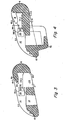
- the BTA of the first, or leading, blade, BTA 1 is generated by a line a - b bisecting the included angle of the first blade 40 and extending from the first blade cutting edge 42.
- the line a - b will be an extension of the plane of the first blade.
- the angle BTA is completed by a second line a - c, extending from the first blade cutting edge 42 to a tangent point c on the guard portion 12.
- the second, or following, blade tangent angle, BT A 2 is defined by a line e - f, similar to the line a - b, and a line e -a extending from the second blade cutting edge 46 to a tangent point immediately preceding to second cutting edge, which in a tandem blade system, is the preceding cutting edge 42.
- BTA 1 and BTA 2 fall within the range of 20° - 32°.
- the S of the first, or leading, blade, S is the distance between the first blade cutting edge 42 and the tangent point c of the immediately preceding surface, that is, the guard portion 12.
- the second, or following, span, S is in the distance between the second blade cutting edge 46 and the tangent point of the immediately preceding surface, namely, the first cutting edge 42.
- S 1 and S 2 fall within the range of .030 - .080 inch.
- the Exp of the first blade, Exp 1 is determined by extending a line c - e between the tangent points immediately preceding and following the first cutting edge, that is, from the guard tangent point c to the second blade cutting edge 46.
- a line h- h is then extended tangent to the first cutting edge 42 and parallel to the line c - e.
- the perpendicular distance between the lines c - e and h - h defines Exp .
- Exp 1 falls within the range of .0015 + .0015 inch.
- Exp The Exp of the second blade, Exp , alternates along the length of the second blade 44, providing alterna- ting second blade exposures Exp and Exp .
- a line a - o is extended between tangent points immediately preceding and following the second cutting edge 46, namely, the first cutting edge 42 and a first cap tangent point o on the fingers 18.
- a line j - j is then extended tangent to the second cutting edge 46 and parallel with.the line a - o.
- Exp 2a is the perpendicular distance between the lines a - o and j - j.
- a line a - p is extended between the first cutting edge 42 and a second cap tangent point p disposed in the recesses between the fingers 18 and located at the top of cap member wall 70 of each recess.
- a line 1 - 1 is then extended tangent to the second cutting edge 46 and parallel with the line a - p.
- Exp 2b is the perpendicular distance between the lines a - p and 1 - 1.
- Exp 2a falls the range of .002 + .002 inch and Exp 2b falls within the range . 004 + .002 inch, Exp 2b being always larger than Exp 2a in a given device.
- the fingers 18 be separated by a distance permitting of entry of skin therebetween during a shaving operation.
- the distance between the fingers 18 ought to be spaced from each other by at least .020 inch, but not more than .080 inc.
Landscapes
- Life Sciences & Earth Sciences (AREA)
- Forests & Forestry (AREA)
- Engineering & Computer Science (AREA)
- Mechanical Engineering (AREA)
- Dry Shavers And Clippers (AREA)
- Led Devices (AREA)
- Semiconductor Lasers (AREA)
- Crystals, And After-Treatments Of Crystals (AREA)
- Cosmetics (AREA)
Priority Applications (1)
| Application Number | Priority Date | Filing Date | Title |
|---|---|---|---|
| AT81109395T ATE11655T1 (de) | 1981-09-03 | 1981-10-30 | Rasierapparat. |
Applications Claiming Priority (2)
| Application Number | Priority Date | Filing Date | Title |
|---|---|---|---|
| US298728 | 1981-09-03 | ||
| US06/298,728 US4407067A (en) | 1980-10-06 | 1981-09-03 | Shaving implement |
Publications (3)
| Publication Number | Publication Date |
|---|---|
| EP0073852A2 true EP0073852A2 (fr) | 1983-03-16 |
| EP0073852A3 EP0073852A3 (en) | 1983-07-20 |
| EP0073852B1 EP0073852B1 (fr) | 1985-02-06 |
Family
ID=23151787
Family Applications (1)
| Application Number | Title | Priority Date | Filing Date |
|---|---|---|---|
| EP81109395A Expired EP0073852B1 (fr) | 1981-09-03 | 1981-10-30 | Rasoir mécanique |
Country Status (4)
| Country | Link |
|---|---|
| EP (1) | EP0073852B1 (fr) |
| KR (1) | KR880002343B1 (fr) |
| AT (1) | ATE11655T1 (fr) |
| DE (1) | DE3168824D1 (fr) |
Cited By (4)
| Publication number | Priority date | Publication date | Assignee | Title |
|---|---|---|---|---|
| EP0563618A1 (fr) * | 1992-03-28 | 1993-10-06 | Wilkinson Sword Gesellschaft mit beschränkter Haftung | Tête de rasage pour rasoir mécanique |
| WO2001023150A1 (fr) | 1999-09-27 | 2001-04-05 | The Gillette Company | Rasoirs de surete |
| WO2005097433A1 (fr) * | 2004-04-02 | 2005-10-20 | Eveready Battery Company, Inc. | Cartouche de rasoir |
| CN114080305A (zh) * | 2019-06-21 | 2022-02-22 | 吉列有限责任公司 | 具有一个或多个皮肤支撑元件的剃刀刀片架 |
Family Cites Families (6)
| Publication number | Priority date | Publication date | Assignee | Title |
|---|---|---|---|---|
| US2374612A (en) * | 1944-01-29 | 1945-04-24 | Joseph M Mellon | Safety razor |
| US3786563A (en) * | 1971-08-31 | 1974-01-22 | Gillette Co | Shaving system |
| US4146958A (en) * | 1976-10-15 | 1979-04-03 | Warner-Lambert Company | Safety razor |
| CA1102537A (fr) * | 1977-09-08 | 1981-06-09 | Frank A. Ferraro | Traduction non-disponible |
| GB1593979A (en) * | 1978-05-30 | 1981-07-22 | Gillette Co | Safety razor |
| ATE20710T1 (de) * | 1981-09-03 | 1986-08-15 | Gillette Co | Rasierapparat. |
-
1981
- 1981-10-06 KR KR1019810003756A patent/KR880002343B1/ko not_active Expired
- 1981-10-30 EP EP81109395A patent/EP0073852B1/fr not_active Expired
- 1981-10-30 AT AT81109395T patent/ATE11655T1/de not_active IP Right Cessation
- 1981-10-30 DE DE8181109395T patent/DE3168824D1/de not_active Expired
Cited By (9)
| Publication number | Priority date | Publication date | Assignee | Title |
|---|---|---|---|---|
| EP0563618A1 (fr) * | 1992-03-28 | 1993-10-06 | Wilkinson Sword Gesellschaft mit beschränkter Haftung | Tête de rasage pour rasoir mécanique |
| US5359774A (en) * | 1992-03-28 | 1994-11-01 | Warner-Lambert Company | Razor head of a wet razor |
| WO2001023150A1 (fr) | 1999-09-27 | 2001-04-05 | The Gillette Company | Rasoirs de surete |
| EP2055450A1 (fr) | 1999-09-27 | 2009-05-06 | The Gillette Company | Rasoirs de sécurité |
| US8117753B2 (en) | 1999-09-27 | 2012-02-21 | The Gillette Company | Safety razors |
| WO2005097433A1 (fr) * | 2004-04-02 | 2005-10-20 | Eveready Battery Company, Inc. | Cartouche de rasoir |
| AU2005231790B2 (en) * | 2004-04-02 | 2012-06-28 | Edgewell Personal Care Brands, Llc | Razor cartridge |
| CN114080305A (zh) * | 2019-06-21 | 2022-02-22 | 吉列有限责任公司 | 具有一个或多个皮肤支撑元件的剃刀刀片架 |
| US12623365B2 (en) | 2019-06-21 | 2026-05-12 | The Gillette Company Llc | Razor cartridge with one or more skin support elements |
Also Published As
| Publication number | Publication date |
|---|---|
| KR880002343B1 (ko) | 1988-10-26 |
| DE3168824D1 (en) | 1985-03-21 |
| ATE11655T1 (de) | 1985-02-15 |
| EP0073852A3 (en) | 1983-07-20 |
| EP0073852B1 (fr) | 1985-02-06 |
| KR830007037A (ko) | 1983-10-14 |
Similar Documents
| Publication | Publication Date | Title |
|---|---|---|
| US4407067A (en) | Shaving implement | |
| US4354312A (en) | Shaving implement, housing therefor, and razor | |
| US6612040B2 (en) | Razors | |
| US6243951B1 (en) | Safety razors | |
| US4288920A (en) | Shaving system with pivotally mounted razor cartridge | |
| US20040181954A1 (en) | Shaving implement having improved pivot axis location | |
| US6397473B1 (en) | Shaving system with uniform shaving forces | |
| US4128937A (en) | Safety razor with serpentine handle | |
| GB2265565A (en) | Razor head of a wet razor | |
| US20080250647A1 (en) | Multi-use shaving implement | |
| EP1273400A1 (fr) | Dispositif de rasage avec des lames statiques et mobiles | |
| US4283850A (en) | Razor blade assembly with a removable blade cartridge | |
| US4282650A (en) | Razor blade assembly | |
| US4282651A (en) | Razor handle | |
| AU6276498A (en) | Safety razors | |
| US4486952A (en) | Shaving implement | |
| US4245388A (en) | Safety razor | |
| EP0073852B1 (fr) | Rasoir mécanique | |
| US4281454A (en) | Shaving system | |
| GB2087287A (en) | Safety razors | |
| GB2081165A (en) | Razors | |
| EP0073853B1 (fr) | Rasoir mécanique | |
| EP0025326A1 (fr) | Système de rasage |
Legal Events
| Date | Code | Title | Description |
|---|---|---|---|
| PUAI | Public reference made under article 153(3) epc to a published international application that has entered the european phase |
Free format text: ORIGINAL CODE: 0009012 |
|
| AK | Designated contracting states |
Designated state(s): AT BE CH DE FR GB IT LI NL SE |
|
| PUAL | Search report despatched |
Free format text: ORIGINAL CODE: 0009013 |
|
| AK | Designated contracting states |
Designated state(s): AT BE CH DE FR GB IT LI NL SE |
|
| 17P | Request for examination filed |
Effective date: 19830629 |
|
| ITF | It: translation for a ep patent filed | ||
| GRAA | (expected) grant |
Free format text: ORIGINAL CODE: 0009210 |
|
| AK | Designated contracting states |
Designated state(s): AT BE CH DE FR GB IT LI NL SE |
|
| REF | Corresponds to: |
Ref document number: 11655 Country of ref document: AT Date of ref document: 19850215 Kind code of ref document: T |
|
| REF | Corresponds to: |
Ref document number: 3168824 Country of ref document: DE Date of ref document: 19850321 |
|
| ET | Fr: translation filed | ||
| PLBE | No opposition filed within time limit |
Free format text: ORIGINAL CODE: 0009261 |
|
| STAA | Information on the status of an ep patent application or granted ep patent |
Free format text: STATUS: NO OPPOSITION FILED WITHIN TIME LIMIT |
|
| 26N | No opposition filed | ||
| GBPC | Gb: european patent ceased through non-payment of renewal fee | ||
| PG25 | Lapsed in a contracting state [announced via postgrant information from national office to epo] |
Ref country code: SE Effective date: 19881031 Ref country code: LI Effective date: 19881031 Ref country code: CH Effective date: 19881031 |
|
| PG25 | Lapsed in a contracting state [announced via postgrant information from national office to epo] |
Ref country code: GB Effective date: 19881121 |
|
| REG | Reference to a national code |
Ref country code: CH Ref legal event code: PL |
|
| ITTA | It: last paid annual fee | ||
| EUG | Se: european patent has lapsed |
Ref document number: 81109395.4 Effective date: 19890614 |
|
| PGFP | Annual fee paid to national office [announced via postgrant information from national office to epo] |
Ref country code: AT Payment date: 19981002 Year of fee payment: 18 |
|
| PGFP | Annual fee paid to national office [announced via postgrant information from national office to epo] |
Ref country code: BE Payment date: 19981021 Year of fee payment: 18 |
|
| PGFP | Annual fee paid to national office [announced via postgrant information from national office to epo] |
Ref country code: FR Payment date: 19990930 Year of fee payment: 19 |
|
| PGFP | Annual fee paid to national office [announced via postgrant information from national office to epo] |
Ref country code: DE Payment date: 19991001 Year of fee payment: 19 |
|
| PGFP | Annual fee paid to national office [announced via postgrant information from national office to epo] |
Ref country code: NL Payment date: 19991007 Year of fee payment: 19 |
|
| PG25 | Lapsed in a contracting state [announced via postgrant information from national office to epo] |
Ref country code: AT Free format text: LAPSE BECAUSE OF NON-PAYMENT OF DUE FEES Effective date: 19991030 |
|
| PG25 | Lapsed in a contracting state [announced via postgrant information from national office to epo] |
Ref country code: BE Free format text: LAPSE BECAUSE OF NON-PAYMENT OF DUE FEES Effective date: 19991031 |
|
| BERE | Be: lapsed |
Owner name: THE GILLETTE CY Effective date: 19991031 |
|
| PG25 | Lapsed in a contracting state [announced via postgrant information from national office to epo] |
Ref country code: NL Free format text: LAPSE BECAUSE OF NON-PAYMENT OF DUE FEES Effective date: 20010501 |
|
| PG25 | Lapsed in a contracting state [announced via postgrant information from national office to epo] |
Ref country code: FR Free format text: LAPSE BECAUSE OF NON-PAYMENT OF DUE FEES Effective date: 20010629 |
|
| NLV4 | Nl: lapsed or anulled due to non-payment of the annual fee |
Effective date: 20010501 |
|
| PG25 | Lapsed in a contracting state [announced via postgrant information from national office to epo] |
Ref country code: DE Free format text: LAPSE BECAUSE OF NON-PAYMENT OF DUE FEES Effective date: 20010703 |
|
| REG | Reference to a national code |
Ref country code: FR Ref legal event code: ST |