EP0073873A2 - Kontaktlinsen-Konstruktion - Google Patents
Kontaktlinsen-Konstruktion Download PDFInfo
- Publication number
- EP0073873A2 EP0073873A2 EP81890192A EP81890192A EP0073873A2 EP 0073873 A2 EP0073873 A2 EP 0073873A2 EP 81890192 A EP81890192 A EP 81890192A EP 81890192 A EP81890192 A EP 81890192A EP 0073873 A2 EP0073873 A2 EP 0073873A2
- Authority
- EP
- European Patent Office
- Prior art keywords
- lens
- contact
- grinding
- sheet
- hydrophilic
- Prior art date
- Legal status (The legal status is an assumption and is not a legal conclusion. Google has not performed a legal analysis and makes no representation as to the accuracy of the status listed.)
- Granted
Links
Images

Classifications
-
- B—PERFORMING OPERATIONS; TRANSPORTING
- B24—GRINDING; POLISHING
- B24B—MACHINES, DEVICES, OR PROCESSES FOR GRINDING OR POLISHING; DRESSING OR CONDITIONING OF ABRADING SURFACES; FEEDING OF GRINDING, POLISHING, OR LAPPING AGENTS
- B24B13/00—Machines or devices designed for grinding or polishing optical surfaces on lenses or surfaces of similar shape on other work; Accessories therefor
- B24B13/01—Specific tools, e.g. bowl-like; Production, dressing or fastening of these tools
- B24B13/012—Specific tools, e.g. bowl-like; Production, dressing or fastening of these tools conformable in shape to the optical surface, e.g. by fluid pressure acting on an elastic membrane
-
- B—PERFORMING OPERATIONS; TRANSPORTING
- B24—GRINDING; POLISHING
- B24B—MACHINES, DEVICES, OR PROCESSES FOR GRINDING OR POLISHING; DRESSING OR CONDITIONING OF ABRADING SURFACES; FEEDING OF GRINDING, POLISHING, OR LAPPING AGENTS
- B24B13/00—Machines or devices designed for grinding or polishing optical surfaces on lenses or surfaces of similar shape on other work; Accessories therefor
- B24B13/02—Machines or devices designed for grinding or polishing optical surfaces on lenses or surfaces of similar shape on other work; Accessories therefor by means of tools with abrading surfaces corresponding in shape with the lenses to be made
-
- B—PERFORMING OPERATIONS; TRANSPORTING
- B29—WORKING OF PLASTICS; WORKING OF SUBSTANCES IN A PLASTIC STATE IN GENERAL
- B29D—PRODUCING PARTICULAR ARTICLES FROM PLASTICS OR FROM SUBSTANCES IN A PLASTIC STATE
- B29D11/00—Producing optical elements, e.g. lenses or prisms
- B29D11/00932—Combined cutting and grinding thereof
Definitions
- the present invention relates to procedures and apparatus facilitating production of lenses. While the invention is particularly applicable to the manufacture of contact lenses, the word "lens" per se as used in the present specification and claims is not restricted to contact lenses, but also includes other types of lenses, mirrors, and the like. The invention is particularly useful in association with the production of multifocal contact lenses. While not restricted to multifocal contact lenses, according to one aspect of the invention multifocal contact lenses - and procedures and apparatus for the manufacture thereof - are made more universal, while according to another aspect of the present invention the production of high quality multifocal contact lenses is facilitated.
- the sponge distorts as the lens is pressed into contact with it, and the sponge thereby provides a biasing force maintaining contact between the polish and the lens.
- a flat sponge is used since the lens may have virtually an infinite number of different power curves, and a flat sponge can accommodate all such curves so that only one polishing tool is required.
- the lens While prior procedures do effect polishing of the lens, a significant portion of the central area of the lens may be worn away during polishing, resulting in a non-uniform product. If this occurs, the lens is not appropriate as a single vision lens, and is not appropriate for manufacture into a multifocal lens.
- non-uniform polishing of the lens occurs since the flat sponge is depressed to a greater degree at the portion thereof in operative association with the center of the lens than are portions thereof in operative association with the periphery of the lens. Since the compression is greater at portions of the sponge associated with the central area of the lens, the pressure applied by the sponge to the polish in contact with the central area of the lens is also greater. Thus non-uniform wear during polishing can occur.
- a lens particularly a dehydrated hydrophilic, a silicone, or a hard contact lens
- the polished lens is entirely suitable for ultimate production of a multifocal lens. This is accomplished by utilizing a pressure responsive flexible sheet mounting polishing compound thereon, and mounted to flex under the influence of fluid pressure without substantial distortion of the sheet itself, and fluid pressure means for biasing the sheet so that the polishing compound associated with it makes contact with the lens surface brought in contact therewith with a uniform force distribution.
- the surface of the lens to be polished is brought into contact with the polishing compound associated with the flexible sheet, causing the sheet to flex, and fluid pressure is applied to the sheet counteracting the flexing as a result of lens contact. Relative rotation between the lens and sheet is then effected so that all portions of the lens surface in contact with the polishing compound are polished to the same extent.
- the flexible sheet preferably is made of a generally non-resilient material, such as a material having the general resiliency properties of a sheet of polytetrafluoroethylene.
- the fluid pressure may comprise a housing having an open face covered by the flexible sheet and defining a substantially fluid-tight volume, with fluid filling the volume and applying a force to the sheet.
- the fluid may be a generally incompressible liquid, such as oil.
- a multifocal hydrophilic or silicone contact lens in a manner consistent with conventional procedures for properly fitting a wearer with contact lenses.
- a practitioner it is advantageous and less expensive for a practitioner to fit a multifocal lens patient with a single vision contact lens first to be sure that the lens is comfortable, positions properly in the patient's eye, and has the correct power.
- Utilization of the single vision contact lens can also provide a good means of determining the distance and near power required by the patient. Since the production of two identical lenses is difficult, it is advantageous (and less expensive) to use the same hydrophilic or silicone contact lens that has been fitted and is known to possess the appropriate characteristics as starting the lens in the production of a multifocal lens.
- silicone as used in the present specification and claims means silicone or other soft or pliable materials suitable for use as contact lenses.
- a method of forming a hydrophilic or silicone contact lens having desired distance and intermediate powers is provided, overcoming the limitations inherent in the prior art.
- the method is practiced by (a) hydrating the hydrophilic contact lens; and (b) without distorting the lens grinding the lens so that it has the desired distance and intermediate powers.
- Step (a) is practiced by fitting a single vision hydrophilic lens in a wearer's eye
- step (b) is practiced by acting on the single vision lens to provide a multifocal hydrophilic contact lens suitable for use by the wearer. It is also possible at any time that it is necessary to change the parameters of the multifocal lens to further act upon it so that it is suitable for, use by the wearer.
- the step (b) in the practice of the method according to this aspect of the invention may be accomplished in a variety of manners.
- the lens may be frozen after hydration, and ground while in the frozen condition.
- the lens may be dehydrated while clamped between a pair of clamping members which prevent distortion of the lens, and the lens ground once dehydrated.
- Another alternative is to provide a chuck having a surface with the same curvature as the base curve of the hydrophilic contact lens, and to bring the lens - while hydrated - into operative contact with the chuck curved surface so that the chuck holds the lens in place, and the lens can then be ground while hydrated and held by the chuck.
- Yet another alternative is to provide a hard contact lens having a power curve substantially the same as the base curve of the hydrophilic lens, and to bring the hydrophilic lens - while hydrated - into contact with the hard contact lens.
- the hard contact lens is then held in an appropriate manner by grinding apparatus and the hydrophilic lens is ground while in contact with and held by the hard lens.
- a method of forming a multifocal lens is provided according to the present invention by acting on the lens so that it is capable of accepting activity from a grinding apparatus, and then grinding the lens without distortion. It is made capable of accepting grinding activity by properly backing it or freezing it.
- FIGURE 1 a dehydrated hydrophilic or hard contact lens 1 is illustrated in association with apparatus - shown generally by reference numeral 10 - for polishing a surface thereof.
- the apparatus 10 is capable of polishing the lens so that all portions thereof (i.e. the central area as compared to the peripheral areas) are worn to the same extent during polishing, making the final lens produced a high quality single vision lens and/or emminently suited for use in the production of a multifocal lens.
- the apparatus 10 includes a means for mounting the lens 1 so that the surface thereof to be polished is accessible.
- Such means preferably take the form of a chuck 12 of a lens cutting tool, the chuck 12 being held in contact with the base curve of the lens 1 by wax or the like.
- the chucks 12 also may be made to be angled.
- Other alternative apparatus could also be utilized, however, and the structure 14 may be the primary mechanism of a lens cutting tool, a motor for rotating the chuck 12 with attached lens 1, or the like.
- the apparatus 10 further comprises a pressure responsive flexible sheet 18 for mounting a polishing compound thereon so that the polishing compound may be brought into contact with the surface of the lens 1 to be polished.
- a suitable polishing compound is held by a polish-holding material.
- a piece of cotton 19 is shown mounted on the top surface of the sheet 18, the cotton 19 comprising polish-holding material, and retaining a polish suitable for polishing the lens 1.
- polish-holding materials such as chamois, may be provided.
- the sheet 18 may be made of a resilient material such as neoprene, since resiliency is not a necessary (or even desired) quality of the sheet 18, it may be made of a generally non-resilient material.
- the sheet 18 may comprise a sheet of polytetrafluoroethylene, or other material having the same general resiliency as polytetrafluoroethylene.
- the apparatus 10 further comprises means for mounting the sheet 18 so that it may flex, under the influence of fluid pressure and the force of the lens 1 when brought into contact therewith, without substantial distortion of the sheet 18 itself.
- a housing 16 is provided having an open face which is covered by the sheet 18.
- the sheet 18 is constructed so that it is loose (not taut) when normally covering the open face of the housing 16, and - for example - may be held in place by an O -ring 20, which may be received by a peripheral groove in housing 16.
- the apparatus 10 further comprises fluid pressure means for biasing the sheet 18 so that polishing compound (e.g. within polish-holding material 19) associated therewith makes contact with the lens 1 surface to be polished with a uniform force distribution, as indicated by the small arrows of equal size in FIGURE 1. This means that all portions of the surface of the lens 1 in contact with the polishing compound associated with the sheet 18 are worn to the same extent during polishing.
- the housing 16 preferably defines a substantially fluid-tight interior volume 22, and the fluid pressure means comprises fluid filling the volume 22 and applying a force to the sheet 18.
- the fluid in volume 22 may be a gas (e.g. air), or a liquid, such as a generally incompressible liquid like water or oil.
- the housing 16 is operatively associated with a device 24 which may comprise either a means for stationarily positioning the housing 16, or for effecting rotation and/or angling of the housing. Relative rotation between the lens 1 and sheet 18 is effected by rotating one of elements 12, 16, or both elements at the same time in like or opposite directions.
- FIGURE 2 is a minor modification of that illustrated in FIGURE 1, with like reference numerals followed by a "'" indicating like components.
- the FIGURE 2 embodiment is particularly adapted for polishing concave lens surfaces, such as the base curve of a hard (or dehydrated soft) contact lens, and to this end the pressure means, sheet 18' mounting means, etcetera are designed so that the sheet 18' normally presents a convex posture, and polish-holding material is disposed on the surface thereof.
- the sheet 18' may normally be maintained convex by pressurizing the interior volume of the housing 16' to a greater extent than it is pressurized in the FIGURE 1 embodiment, such as by supplying fluid under high pressure from pump 28 through line 30 into the interior of the volume defined by housing 16'. If desired, the housing 16' need not be entirely fluid-tight, and the pump 28 can continuously supply fluid to the housing 16', with any leakage being made up by newly supplied fluid.
- the surface of the lens 1 to be polished is brought into contact with the polishing compound (in material 19) associated with the sheet 18, causing the sheet 18 to flex as illustrated in FIGURE 1.
- Fluid pressure is applied to the sheet 18, as indicated by the small arrows in FIGURE 1, counteracting the flexing of sheet 18 as a result of the force applied by lens 1, the pressure application being practiced so that polishing compound (in material 19) associated with the sheet 18 makes contact with the lens 1 surface with a uniform force distribution.
- one or both of the elements 12, 16 are rotated to effect relative rotation between the lens 1 and sheet 18 so that all portions of the lens 1 surface in contact with the polishing compound are worn to the same extent during polishing.
- the lens may be formed into a multifocal lens, such as by utilizing the apparatus illustrated in FIGURES 6 and 7.
- a method of forming a hydrophilic contact lens having desired distance and intermediate powers is provided.
- the method is practiced by (a) hydrating a hydrophilic contact lens 2 (see FIGURES 3 through 5); and (b) without distoring the lens 2, grinding it so that it has the desired distance and itnermediate powers, such as by utilizing the apparatus of FIGURES 6 and 7.
- step (a) would be practiced by fitting a single vision hydrophilic lens in a patient's eye, the lens of course necessarily being hydrated in order to be fit properly.
- step (b) preferably being practiced by acting on the single vision lens to provide a multifocal hydrophilic contact lens suitable for use by the patient.
- Alternative procedures for grinding the lens without distortion can be understood with reference to FIGURES 3 through 5.
- Several such procedures are also applicable to silicone lenses (2), such lenses being rendered capable of accepting activity from a grinding apparatus before distortion-free grinding thereof is practiced.
- One manner of practicing distortion-free grinding of a hydrophilic or silicone contact lens 2 is to provide a chuck 33 (see FIGURE 3) having a surface 34 with the same curvature as the base curve of the lens 2.
- the chuck 33 may be made of a variety of materials such as brass, plastic, and stainless steel. Since there are only a handful of different conventional base curves for hydrophilic and silicone contact lenses, only a handful of chucks 33 with different convex surfaces 34 need be provided to accommodate all conventional hydrophilic and silicone contact lenses.
- the lens 2 - while hydrated - is brought into operative contact with the surface 34, the wet lens 2 [see water film 51 clinging tightly to the chuck 33. A silicone lens also will cling if wet.
- the lens 2 may then be ground to produce a multifocal lens such as by utilizing the apparatus shown in FIGURES 6 and 7, the flexible member 35 of the grinding apparatus of FIGURE 6, with polishing compound (36) thereon being illustrated schematically in FIGURE 3 in association with the lens 2 (if a hydrophilic lens). Even if dehydration of the lens 2 should occur during processing, because of the interengagement between surface 34 and lens 2 - and the action of the flexible member 35 on lens 2 - it will not distort.
- FIGURE 4 alternative components for facilitating distortion-free grinding of a hydrophilic or silicone contact lens 2 are illustrated.
- a hard contact lens 3 is provided having a power curve the same as the base curve of the silicone or hydrophilic lens 2.
- the base curve of the lens 2 when wet is brought into contact with the power curve of the hard lens 3, a clinging action therebetween taking place.
- the hard lens 3 is then mounted onto a suitable component of the polishing apparatus such as that illustrated in FIGURE 6.
- the lenses 2, 3 are shown in association with the hollow sleeve 38 and flexible member 35 of the apparatus of FIGURE 6, the hard lens 3 being held to the hollow sleeve 38 by an annular piece of double-faced tape 40.
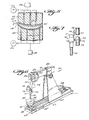
- FIGURE 5 schematically illustrates components for acting on a hydrated hydrophilic contact lens 2 to effect distortion-free dehydration thereof.
- a pair of clamping members 43, 44 are provided, each having a surface generally corresponding to one of the power and base curves of the lens 2.
- clamping member 43 has a surface 45 generally corresponding to the base curve of the lens 2
- clamping member 44 has a surface 46 generally corresponding to the power curve of the lens 2.
- a clamping force sufficient to prevent distortion is applied to the members 43, 44 through the force application structures 48, 49, and while a clamping force is being supplied the lens 2 is dried. Drying may be accomplished utilizing drying chemicals, or by heating the elements 43, 44 (and coincidentally the surfaces 45, 46), and/or by circulating drying gas past the lens 2.
- FIGURE 5 a mechanism facilitating circulation of drying gas around the lens 2 is schematically illustrated.
- Such mechanism includes a plurality of passageways 50, 50' formed in the members 43, 44, with drying gas provided from sources 51, 52 circulating through the passageways 50, 50'.
- the gas passing through the passageways 50, 50' will ultimately exit to the ambient air, and effecting dehydration of the lens 2.
- the lens 2 Once the lens 2 is dehydrated in this distortion-free manner, it may be processed utilizing the apparatus of FIGURE 6 in the same manner as if it had never been hydrated.
- a hydrophilic or silicone lens 2 may be frozen (while hydrated if a hydrophilic lens). When frozen, the lens 2 may be brought in contact with suitable apparatus (e.g. hollow sleeve 38 and flexible member 35) of a grinding apparatus, and ground in substantially the same manner as a hard contact lens.
- suitable apparatus e.g. hollow sleeve 38 and flexible member 35
- Basic components of the grinding apparatus indicated generally by reference numeral 60, of FIGURE 6 include the rotatable bowl 62 on which the flexible member 35 (e.g. a chamois skin) is mounted.
- a spinning bowl support 63 is fastened to a base 64 for the apparatus 60 by a strap 65, and cylinder 66 supports the bowl 62 for rotation about a generally vertical axis.
- a pulley mounted on member 66 is rotated by a V belt 67 which connects the pulley to a motor 68.
- a contact lens (such as lens 1 illustrated in FIGURE 6) to be ground is mounted by hollow sleeve 38 and doublesided tape 40 to a shaft 70, which is mounted so as to be either rotated by power or freely rotatable within a bore in clamped member 71.
- Clamping member 72 holds clamped member 71, and pivot pin 73 is rigidly attached to rotatable clamping member 72.
- Pin 73 passes through a bore 74 in the lower end of vertical shaft 75, and a wing nut 76 is provided on the threaded end of pin 73 to lock the members 71, 72 in any relative angular position to which they have been moved.
- a semicircular dial 78 which can be calibrated in degrees, is fixed to shaft 75, while pointer 79 is fixed to clamping member 72.
- the components also can be designed so that shaft 75 can be moved sideways and locked in any position to which it has been moved.
- Traversing member 81 can be moved to any relative horizontal position with respect to sleeve 82 to position the shaft 75 relative to bowl 62.
- Shaft 75 can be vertically reciprocated in cylindrical guide sleeve 84 by rotation of wheel 85 connected to sprocket 86 which engages a rack (not shown) formed on shaft 75.
- the lens e.g. lens 1
- the clamped member 70 is at a fixed angular attitude with respect to the vertical (i.e. vertical shaft 75).
- the spinning flexible member 35 with grinding compound 36 thereon contacts the center portion of lens 1 and not only effects appropriate grinding of the lens to the distance and intermediate correction, but the final lens produced need not be polished.
Landscapes
- Engineering & Computer Science (AREA)
- Mechanical Engineering (AREA)
- Health & Medical Sciences (AREA)
- Manufacturing & Machinery (AREA)
- Ophthalmology & Optometry (AREA)
- Physics & Mathematics (AREA)
- Fluid Mechanics (AREA)
- Grinding And Polishing Of Tertiary Curved Surfaces And Surfaces With Complex Shapes (AREA)
- Eyeglasses (AREA)
- Purses, Travelling Bags, Baskets, Or Suitcases (AREA)
- Pens And Brushes (AREA)
Priority Applications (1)
| Application Number | Priority Date | Filing Date | Title |
|---|---|---|---|
| AT81890192T ATE20443T1 (de) | 1981-09-08 | 1981-11-24 | Kontaktlinsen-konstruktion. |
Applications Claiming Priority (2)
| Application Number | Priority Date | Filing Date | Title |
|---|---|---|---|
| US299949 | 1981-09-08 | ||
| US06/299,949 US4458454A (en) | 1981-09-08 | 1981-09-08 | Methods of shaping contact lens |
Publications (3)
| Publication Number | Publication Date |
|---|---|
| EP0073873A2 true EP0073873A2 (de) | 1983-03-16 |
| EP0073873A3 EP0073873A3 (en) | 1983-06-22 |
| EP0073873B1 EP0073873B1 (de) | 1986-06-18 |
Family
ID=23157013
Family Applications (1)
| Application Number | Title | Priority Date | Filing Date |
|---|---|---|---|
| EP81890192A Expired EP0073873B1 (de) | 1981-09-08 | 1981-11-24 | Kontaktlinsen-Konstruktion |
Country Status (7)
| Country | Link |
|---|---|
| US (1) | US4458454A (de) |
| EP (1) | EP0073873B1 (de) |
| JP (1) | JPS5851063A (de) |
| AT (1) | ATE20443T1 (de) |
| AU (1) | AU548722B2 (de) |
| CA (1) | CA1185795A (de) |
| DE (1) | DE3174850D1 (de) |
Cited By (1)
| Publication number | Priority date | Publication date | Assignee | Title |
|---|---|---|---|---|
| CN103167948A (zh) * | 2010-10-21 | 2013-06-19 | 依视路国际集团(光学总公司) | 将薄膜结构贴覆至透镜毛坯上的工艺 |
Families Citing this family (15)
| Publication number | Priority date | Publication date | Assignee | Title |
|---|---|---|---|---|
| JP2814495B2 (ja) * | 1988-09-16 | 1998-10-22 | セイコーエプソン株式会社 | コンタクトレンズの製造方法及び製造装置 |
| JP2896802B2 (ja) * | 1990-06-05 | 1999-05-31 | セイコーインスツルメンツ株式会社 | 光ファイバコネクタプラグの製造方法 |
| US5205083A (en) * | 1991-10-24 | 1993-04-27 | Pettibone Dennis R | Method and apparatus for polishing optical lenses |
| JP3024417B2 (ja) * | 1992-02-12 | 2000-03-21 | 住友金属工業株式会社 | 研磨装置 |
| US6439979B1 (en) | 1992-02-12 | 2002-08-27 | Tokyo Electron Limited | Polishing apparatus and polishing method using the same |
| JP2616736B2 (ja) * | 1995-01-25 | 1997-06-04 | 日本電気株式会社 | ウエーハ研磨装置 |
| US6176579B1 (en) | 1999-07-07 | 2001-01-23 | Softfocal Co., Inc | Bifocal contact lens with toric transition |
| US6428573B2 (en) | 2000-02-03 | 2002-08-06 | Howard J. Barnett | Intraocular multifocal lens construction |
| US6609958B2 (en) | 2000-12-21 | 2003-08-26 | Bausch & Lomb Incorporated | Apparatus and method for edging a contact lens |
| US6589102B2 (en) * | 2001-01-30 | 2003-07-08 | Larsen Equipment Design, Inc. | Surface polishing method and apparatus |
| US7011571B2 (en) | 2003-10-02 | 2006-03-14 | Radtek Corporation | Blocking apparatus for lens manufacturing including automatic wax delivery system |
| US7059037B2 (en) | 2003-10-02 | 2006-06-13 | Radtek Corporation | Blocking apparatus providing an adjustable offset for precision alignment |
| US20050075060A1 (en) * | 2003-10-02 | 2005-04-07 | Konrad Bergandy | Apparatus for precision alignment during blocking process of lens manufacturing |
| EP1655102B1 (de) * | 2004-11-09 | 2008-01-09 | Seiko Epson Corporation | Elastisches Polierwerkzeug und Verfahren zum Polieren einer Linse mit einem solchen Werkzeug |
| EP2087082A2 (de) * | 2006-10-23 | 2009-08-12 | The Lubrizol Corporation | Antiverschleissmittel und schmiermittelzusammensetzung daraus |
Family Cites Families (17)
| Publication number | Priority date | Publication date | Assignee | Title |
|---|---|---|---|---|
| US490419A (en) * | 1893-01-24 | Buffing-machine | ||
| US1166639A (en) * | 1915-12-08 | 1916-01-04 | Harry W Hill | Lens-polishing machine. |
| US2328533A (en) * | 1941-12-26 | 1943-08-31 | Alncin Inc | Glass article and method of manufacture thereof |
| NL248517A (de) * | 1959-02-18 | |||
| US3112581A (en) * | 1961-02-03 | 1963-12-03 | Hoffman Jacob | Contact lens finishing machine |
| US3430391A (en) * | 1962-12-31 | 1969-03-04 | Indiana Contact Lens Inc | Apparatus for altering the power of a corneal contact lens |
| US3258879A (en) * | 1963-11-04 | 1966-07-05 | Carlyle A Edelstein | Apparatus for grinding contact lenses |
| US3471976A (en) * | 1964-01-27 | 1969-10-14 | Howard J Barnett | Process for making a multifocal contact lens |
| US3420006A (en) * | 1964-01-27 | 1969-01-07 | Howard J Barnett | Apparatus for grinding multifocal lens |
| US3458959A (en) * | 1965-10-24 | 1969-08-05 | Urocon Inc | Apparatus and method for edge finishing contact lenses |
| US3514908A (en) * | 1967-11-29 | 1970-06-02 | Bausch & Lomb | Process for finishing contact lenses |
| FR2076643A5 (de) * | 1970-01-22 | 1971-10-15 | Silor | |
| US3874124A (en) * | 1973-02-20 | 1975-04-01 | Harry C Morgan | Method and apparatus for machining and/or polishing molded elastomer materials |
| JPS5036319A (de) * | 1973-08-02 | 1975-04-05 | ||
| WO1979000082A1 (en) * | 1977-08-02 | 1979-02-22 | Automated Optics | Method and apparatus adapted for automatic or semi-automatic fabrication of ultra-precision ophthalmic lenses,e.g.,contact lenses |
| JPS5613583A (en) * | 1979-07-13 | 1981-02-09 | Nec Corp | Revolving-magnetic-field driver of series resonance type |
| US4430391A (en) * | 1982-07-19 | 1984-02-07 | Energy Conversion Devices, Inc. | Fuel cell cathode |
-
1981
- 1981-09-08 US US06/299,949 patent/US4458454A/en not_active Expired - Lifetime
- 1981-11-18 AU AU77617/81A patent/AU548722B2/en not_active Ceased
- 1981-11-24 DE DE8181890192T patent/DE3174850D1/de not_active Expired
- 1981-11-24 CA CA000390743A patent/CA1185795A/en not_active Expired
- 1981-11-24 AT AT81890192T patent/ATE20443T1/de not_active IP Right Cessation
- 1981-11-24 EP EP81890192A patent/EP0073873B1/de not_active Expired
-
1982
- 1982-09-07 JP JP57154733A patent/JPS5851063A/ja active Pending
Cited By (3)
| Publication number | Priority date | Publication date | Assignee | Title |
|---|---|---|---|---|
| CN103167948A (zh) * | 2010-10-21 | 2013-06-19 | 依视路国际集团(光学总公司) | 将薄膜结构贴覆至透镜毛坯上的工艺 |
| CN103167948B (zh) * | 2010-10-21 | 2015-09-02 | 依视路国际集团(光学总公司) | 将薄膜结构贴覆至透镜毛坯上的工艺 |
| US9778485B2 (en) | 2010-10-21 | 2017-10-03 | Essilor International (Compagnie Generale D'optique) | Process for applying a film structure onto a lens blank |
Also Published As
| Publication number | Publication date |
|---|---|
| ATE20443T1 (de) | 1986-07-15 |
| DE3174850D1 (en) | 1986-07-24 |
| EP0073873A3 (en) | 1983-06-22 |
| AU548722B2 (en) | 1986-01-02 |
| AU7761781A (en) | 1983-03-17 |
| CA1185795A (en) | 1985-04-23 |
| US4458454A (en) | 1984-07-10 |
| EP0073873B1 (de) | 1986-06-18 |
| JPS5851063A (ja) | 1983-03-25 |
Similar Documents
| Publication | Publication Date | Title |
|---|---|---|
| US4458454A (en) | Methods of shaping contact lens | |
| CA1299874C (en) | Universal lens polishing tool, polishing apparatus and method of polishing | |
| US3420006A (en) | Apparatus for grinding multifocal lens | |
| US5255474A (en) | Polishing spindle | |
| JPS63300852A (ja) | 光ファイバの端面研磨装置 | |
| US3860399A (en) | Liquid blocking technique for working a member to precise optical tolerances | |
| US2328533A (en) | Glass article and method of manufacture thereof | |
| US11454579B2 (en) | Base material evaluation method and curved glass evaluation device | |
| US4358913A (en) | Lens block | |
| AU610937B2 (en) | Toric finer-polisher | |
| US4267672A (en) | Lens processing method | |
| US5150547A (en) | Ophthalmic lens prism blocking ring | |
| US3471976A (en) | Process for making a multifocal contact lens | |
| US3430391A (en) | Apparatus for altering the power of a corneal contact lens | |
| EP0971810B1 (de) | Verfahren und vorrichtung zum poliren von optischen linsen | |
| US3238676A (en) | Method for altering the power of a corneal contact lens | |
| US4341045A (en) | Adapter chuck for mounting lens blanks | |
| US3360889A (en) | Method for altering the power of a corneal contact lens | |
| US3093447A (en) | Method of casting optical elements | |
| US3258879A (en) | Apparatus for grinding contact lenses | |
| US2259006A (en) | Lens holder | |
| US4297008A (en) | Method and apparatus for making a non spherical beveled contact lens | |
| US4382351A (en) | Chuck assembly for lens block | |
| US2040242A (en) | Method and means for surfacing solid bifocal lenses | |
| JPS6284968A (ja) | ステンレス鋼の鏡面仕上げ方法 |
Legal Events
| Date | Code | Title | Description |
|---|---|---|---|
| PUAI | Public reference made under article 153(3) epc to a published international application that has entered the european phase |
Free format text: ORIGINAL CODE: 0009012 |
|
| AK | Designated contracting states |
Designated state(s): AT BE CH DE FR GB IT LI LU NL SE |
|
| PUAL | Search report despatched |
Free format text: ORIGINAL CODE: 0009013 |
|
| AK | Designated contracting states |
Designated state(s): AT BE CH DE FR GB IT LI LU NL SE |
|
| 17P | Request for examination filed |
Effective date: 19831213 |
|
| ITF | It: translation for a ep patent filed | ||
| GRAA | (expected) grant |
Free format text: ORIGINAL CODE: 0009210 |
|
| AK | Designated contracting states |
Kind code of ref document: B1 Designated state(s): AT BE CH DE FR GB IT LI LU NL SE |
|
| PG25 | Lapsed in a contracting state [announced via postgrant information from national office to epo] |
Ref country code: NL Effective date: 19860618 Ref country code: LI Effective date: 19860618 Ref country code: CH Effective date: 19860618 Ref country code: BE Effective date: 19860618 Ref country code: AT Effective date: 19860618 |
|
| REF | Corresponds to: |
Ref document number: 20443 Country of ref document: AT Date of ref document: 19860715 Kind code of ref document: T |
|
| PG25 | Lapsed in a contracting state [announced via postgrant information from national office to epo] |
Ref country code: SE Effective date: 19860630 |
|
| REF | Corresponds to: |
Ref document number: 3174850 Country of ref document: DE Date of ref document: 19860724 |
|
| ET | Fr: translation filed | ||
| REG | Reference to a national code |
Ref country code: CH Ref legal event code: PL |
|
| PG25 | Lapsed in a contracting state [announced via postgrant information from national office to epo] |
Ref country code: LU Free format text: LAPSE BECAUSE OF NON-PAYMENT OF DUE FEES Effective date: 19861130 |
|
| NLV1 | Nl: lapsed or annulled due to failure to fulfill the requirements of art. 29p and 29m of the patents act | ||
| PLBE | No opposition filed within time limit |
Free format text: ORIGINAL CODE: 0009261 |
|
| STAA | Information on the status of an ep patent application or granted ep patent |
Free format text: STATUS: NO OPPOSITION FILED WITHIN TIME LIMIT |
|
| 26N | No opposition filed | ||
| ITTA | It: last paid annual fee | ||
| PGFP | Annual fee paid to national office [announced via postgrant information from national office to epo] |
Ref country code: FR Payment date: 19991109 Year of fee payment: 19 |
|
| PGFP | Annual fee paid to national office [announced via postgrant information from national office to epo] |
Ref country code: GB Payment date: 19991124 Year of fee payment: 19 |
|
| PGFP | Annual fee paid to national office [announced via postgrant information from national office to epo] |
Ref country code: DE Payment date: 19991129 Year of fee payment: 19 |
|
| PG25 | Lapsed in a contracting state [announced via postgrant information from national office to epo] |
Ref country code: GB Free format text: LAPSE BECAUSE OF NON-PAYMENT OF DUE FEES Effective date: 20001124 |
|
| GBPC | Gb: european patent ceased through non-payment of renewal fee |
Effective date: 20001124 |
|
| PG25 | Lapsed in a contracting state [announced via postgrant information from national office to epo] |
Ref country code: FR Free format text: LAPSE BECAUSE OF NON-PAYMENT OF DUE FEES Effective date: 20010731 |
|
| PG25 | Lapsed in a contracting state [announced via postgrant information from national office to epo] |
Ref country code: DE Free format text: LAPSE BECAUSE OF NON-PAYMENT OF DUE FEES Effective date: 20010801 |
|
| REG | Reference to a national code |
Ref country code: FR Ref legal event code: ST |