EP0073952A2 - Régulation électronique pour un système d'allumage - Google Patents
Régulation électronique pour un système d'allumage Download PDFInfo
- Publication number
- EP0073952A2 EP0073952A2 EP82107349A EP82107349A EP0073952A2 EP 0073952 A2 EP0073952 A2 EP 0073952A2 EP 82107349 A EP82107349 A EP 82107349A EP 82107349 A EP82107349 A EP 82107349A EP 0073952 A2 EP0073952 A2 EP 0073952A2
- Authority
- EP
- European Patent Office
- Prior art keywords
- signal
- edge
- control signal
- electronically controlled
- ignition system
- Prior art date
- Legal status (The legal status is an assumption and is not a legal conclusion. Google has not performed a legal analysis and makes no representation as to the accuracy of the status listed.)
- Granted
Links
Images





Classifications
-
- F—MECHANICAL ENGINEERING; LIGHTING; HEATING; WEAPONS; BLASTING
- F02—COMBUSTION ENGINES; HOT-GAS OR COMBUSTION-PRODUCT ENGINE PLANTS
- F02P—IGNITION, OTHER THAN COMPRESSION IGNITION, FOR INTERNAL-COMBUSTION ENGINES; TESTING OF IGNITION TIMING IN COMPRESSION-IGNITION ENGINES
- F02P5/00—Advancing or retarding ignition; Control therefor
- F02P5/04—Advancing or retarding ignition; Control therefor automatically, as a function of the working conditions of the engine or vehicle or of the atmospheric conditions
- F02P5/145—Advancing or retarding ignition; Control therefor automatically, as a function of the working conditions of the engine or vehicle or of the atmospheric conditions using electrical means
- F02P5/155—Analogue data processing
-
- Y—GENERAL TAGGING OF NEW TECHNOLOGICAL DEVELOPMENTS; GENERAL TAGGING OF CROSS-SECTIONAL TECHNOLOGIES SPANNING OVER SEVERAL SECTIONS OF THE IPC; TECHNICAL SUBJECTS COVERED BY FORMER USPC CROSS-REFERENCE ART COLLECTIONS [XRACs] AND DIGESTS
- Y02—TECHNOLOGIES OR APPLICATIONS FOR MITIGATION OR ADAPTATION AGAINST CLIMATE CHANGE
- Y02T—CLIMATE CHANGE MITIGATION TECHNOLOGIES RELATED TO TRANSPORTATION
- Y02T10/00—Road transport of goods or passengers
- Y02T10/10—Internal combustion engine [ICE] based vehicles
- Y02T10/40—Engine management systems
Definitions
- the invention relates to an electronically controlled ignition system for an internal combustion engine, in which a signal correcting the ignition is derived from a control signal derived directly from an ignition pulse generator.
- Control signals for the ignition process of an engine which are derived from an ignition pulse sensor sensing the position of the rotor, have to be corrected for various reasons, regardless of the speed or depending on the speed. It is therefore an object of the present invention to provide an electronically controlled ignition system in which a correction signal is obtained in a very simple manner from the control signal derived from the ignition pulse generator.
- This object is achieved in that within each period of the meandering control signal (A) from only one edge (X) of this control signal a sawtooth-shaped signal (B) with a rising edge (Bl) and a falling edge (B2) is generated, the ratio of the steepness of the two edges is a measure of the change in the correction signal (F) compared to the control signal (A).
- Such an electronically controlled ignition system has the advantage that it is not necessary to use both edges of the meandering control signal within one period to generate the correction variable.
- only one edge of the meandering control signal is used within one to generate this correction variable Period of this control signal used, while the respective position of the second edge of the control signal has no influence on the measure of the correction value.
- an edge of the meandering control signal preferably triggers the falling edge of the sawtooth-shaped signal within one period. This falling edge ends when a predeterminable value is reached by triggering the rising edge, which in turn ends when the control edge of the control signal occurs in the subsequent period and is replaced by the falling edge.
- the control edge of the control signal preferably consists of the high-low edge of the meandering control signal.
- the correction signal compared to the control signal is extended by the time determined by the falling edge of the saw-shaped signal.
- the sawtooth-shaped signal is preferably given by the voltage profile across a capacitor. This capacitor is charged with the currents which determine the steepness of the signal edges until a control edge of the control signal occurs and then discharged again until a predefinable reference voltage is reached.
- a control signal A according to FIG. 1 a is derived from the output signal of an ignition pulse generator, for example an induction transmitter. This control signal is meandering and has the period T. Within a period T, the falling high-low edge X is used as a control edge for generating a sawtooth-shaped signal according to FIG. 1b.
- the discharge current I E of a current source Q 1 is released in a basic circuit according to FIG. 2, so that the previously charged capacitor C is discharged according to the falling edge B 2 in FIG. 1b via the switch S in the position "a" .
- the capacitor voltage U e is compared on a comparator K with the fixed voltage U F. If U C drops below U F , then the output of the comparator K switches the switch S to the "b" position, as a result of which the capacitor C is charged with the charging current I L of the constant current source Q 2 , so that the voltage across the capacitor C in accordance with Rising edge B 1 rises in FIG. 1b.
- the slopes of the flanks B1 and B 2 are predetermined by the size of the charging or discharging current from the current sources Q 1 and Q 2 .
- the overall profile of the voltage U e across the capacitor is shown as the functional profile B in FIG. 1b.
- the control pulse according to FIG. 1 a is now extended by the correction variable, namely the time .DELTA.t, which corresponds to the duration of the discharge process of the capacitor and thus to the falling edge B 2 .
- the correction signal F obtained in this way is shown in FIG. 1c.
- This correction signal can, for example, be used instead of the control signal A to control the current in the primary side of the ignition coil.
- the primary current I pr begins to flow with the low-high edge of the correction signal F and is abruptly terminated with the occurrence of the high-low edge of this correction signal F, so that ignition occurs, which is shown in the figure ld is indicated by ignition arrows. With that the Ignition timing is delayed by the time ⁇ t compared to the ignition timing that would have resulted if the control signal A had been used.
- the closing angle of an engine ignition can also be adjusted according to the requirements.
- the electronically controlled ignition system according to the invention is particularly suitable for generating a correction signal with which the advance of the ignition timing caused by an induction transmitter compared to the mechanical position of the rotor can be compensated for or overcompensated.
- the voltage zero crossing of the control edge X of the control signal A which triggers the ignition according to FIG. 1 a is not in accordance with the mechanical position of the rotor.
- Figure 3 shows that in the start phase at 150 U / min the zero crossing of the control signal leads by 4% - 6%, based on the period, and at the maximum speed lagging about 2%. Since the ignition spark is triggered with the voltage zero crossing of the control signal, the induction transmitter behaves contrary to the requirements that an engine requires for good running behavior, especially in the starting phase. With the help of the electronically controlled ignition according to the invention, the advance caused by the induction generator is eliminated in the starting phase.
- the ignition system can be used universally for a wide range of engines and vehicles.
- One and the same ignition system can, for example, be tuned to the needs of the individual engines with regard to the ignition angle by either fixed or operating parameter-dependent wiring.
- This standardization of the ignition system results in a cost reduction for the manufacturer, a reduction in the amount of storage and, furthermore, confusion can be avoided.
- the correction signal can be switched on and off in different ways depending on the respective operating and operating conditions.
- the correction signal can only be activated during the starting process of the internal combustion engine.
- a signal representative of this process is present, for example, at output "50" of an ignition / starter switch.
- Such an ignition system results in a particularly simple circuit structure, since the speed-specific switching elements that are normally provided and which switch off the correction signal when a predetermined speed is reached can be dispensed with.
- the correction signal can also be switchable as a function of parameters of the internal combustion engine.
- the engine temperature is a good choice. It has been shown that the correction signal significantly improves the starting process, especially at low operating temperatures, while the control signal alone ensures a satisfactory starting process in the case of a so-called hot start.
- correction signal can be deactivated in certain vehicle models or engine designs. In these cases, although a simplified Z ündsystem, wherein the correction signal is not generated enough. However, this would require two different types of ignition systems and would reverse the advantages of the invention.
- the voltage U IND which is supplied by an induction sensor, is plotted in FIG. 4a.
- T denotes the period and U v the comparative voltage of a comparator.
- 4b shows the meandering voltage curve A at the output of the comparator.
- 4d shows the corrected signal F, the high phases of which are extended by the desired time interval .DELTA.t such that the high-low edge which triggers the ignition is delayed by this time .DELTA.t compared to the control edge X of the control signal A. It is thereby achieved that the primary current I pr according to FIG. 4e is likewise delayed by the time .DELTA.t in the manner which triggers the ignition.
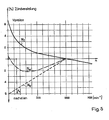
- FIG. 5 shows the starting phase of the engine on an enlarged scale compared to FIG. 3.
- the curve profile N I shows the advance of the zero crossing of the control signal A depending on the speed n between 0 and 1000 revolutions per minute.
- the electronic compensation provided is represented by the function curve of the straight line N E. This straight line has the function:
- the ratio of the charging current I L to the discharge current I E in a circuit arrangement according to FIG. 2 is one value to choose.
- the percentage offset ⁇ t / T of the correction signal F compared to the control signal A is constant from the lowest selected speed, for example at 50 rpm, to the highest speeds and would be 6 in the example given %.
- the percentage value of the compensation N E decreases with increasing speed and reaches the value O at approximately 1000 rpm.
- the falling edge of the sawtooth-shaped signal is compared with a fixed voltage which is greater than the reference voltage.
- the correction signal is then extended compared to the control signal by a time interval ⁇ t, which is given by the time duration of the falling edge of the sawtooth-shaped signal until the newly inserted fixed voltage is reached.
- the potential distance between the newly introduced fixed voltage U s and the reference voltage U F must be selected so that when a certain threshold speed of the rotor is reached - for example at 1000 rpm - the maximum saw signal shape no longer reaches the fixed voltage value U S , so that from this threshold speed the control signal A is no longer extended or the control edge X is no longer delayed. Below this threshold speed, on the other hand, the extension of the correction signal or the delay of the Ignition triggering flank with decreasing speed.
- the compensation should be the ignition timing is 6%.
- the maximum value of the sawtooth-shaped signal B at 1000 rpm coincides with the fixed voltage value U s when the potential spacing ⁇ U is approximately 130 mV between the fixed voltage U S and the reference voltage U F.
- FIGS. 6a to 6c and 7a to 7b The conditions with the insertion of the fixed voltage U S are shown in FIGS. 6a to 6c and 7a to 7b.
- the intersection between the falling edge B 2 of the sawtooth-shaped signal B with the fixed voltage U S almost coincides with the intersection of the falling edge B 2 and the reference voltage U F according to FIG. 6b.
- the potential difference .DELTA.U is small compared to the maximum voltage of the sawtooth-shaped signal B.
- the delay in the ignition point is approximately 5.2% at 125 rpm, approximately 4.5% at 250 rpm, approximately 3% at 500 rpm and approximately 0 at 1000 rpm Percent.
- Figures 7a and 7b show the conditions at a speed of about 1000 revolutions per minute.
- the sawtooth-shaped signal B only oscillates between the fixed voltage U S and the reference voltage U F due to the selected dimensioning at 1000 rpm.
- the time interval ⁇ t between the maximum value of the sawtooth-shaped signal B and the fixed voltage U S thus becomes 1000 rpm. to zero.
- the correction signal F is then identical to the control signal A derived from the induction transmitter.
- the ignition timing is therefore only compensated in the speed range between 0 and 1000 rpm.
- the circuit design of the electronically controlled ignition system there are current sources via which the capacitor for generating the sawtooth-shaped signal B is charged and discharged in the manner described.
- a comparator K 1 on which the capacitor voltage is compared with the reference voltage U F.
- the capacitor voltage is compared with the fixed voltage U s at a second comparator K 2 .
- the circuit contains a bistable flip-flop FF, which is converted into one stable state via the output of the first comparator and from the low-high edge of the control signal A into the other stable state.
- the output signal F is obtained in that the circuit contains a NOR gate G, one input of which is the output signal of the flip-flop FF and the other input of which is the off output signal of the second comparator K2 is supplied.
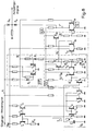
- FIG. 8 Such a circuit is shown in FIG. 8.
- the capacitor C is charged with the charging current I L and discharged with the discharge current I E.
- the charging current I L is set with the current mirror from the transistors T 1 and T 2 in connection with the resistor R 3 in the collector branch of the transistor T 1 .
- the discharge current is set via the current mirror from the transistors T 3 , T 4 and T 5 , the following must apply to the ratio of the active transistor areas of the transistors T 4 and T 5 :
- the voltage U C across the capacitor C is applied to one input of the comparator K 1 via the transistor T 8 .
- the comparator K 1 consists of the differential amplifier with the transistors T 9 and T 10 and the final transistor T 11 .
- the capacitor voltage B increased by the base emitter voltage of the transistor 8 is thus at the base electrode of the transistor T 9 .
- the reference voltage U F is at the second input of the comparator K 1 , that is to say at the base electrode of the transistor T 10 . It is raised compared to the actual reference voltage U F set with the voltage divider R 1 , R 2 , R 4 by the base emitter voltage of the transistor T 19 in order to compensate for the corresponding base emitter voltage of the transistor T 8 .
- the output signal of the comparator K 1 is given as a trigger signal T X to the input of the bistable flip-flop F F.
- FIG. 9a shows the input control signal A which, according to FIG. 8, is coupled out via the diode D 4 to the output of the circuit and is also fed to the base electrode of the transistor T 6 and the second input of the bistable multivibrator FF.
- FIG. 9b shows the sawtooth-shaped signal B at the input of the comparator K. Furthermore, the reference voltage U F and the fixed voltage U S are entered in FIG. 9b.
- the comparator K 1 only outputs an output signal T according to FIG. 9c when the sawtooth-shaped signal B reaches the reference voltage U F.
- the output of the comparator K 1 at the collector of the transistor T 11 thus has a low level if U C + U BE > U F 'applies. With U c + U BE ⁇ U F ', the output signal T X has the high level.
- the signal E shown in FIG. 9e is tapped at the output of the comparator K 2 , which corresponds to the collector of the transistor T 16 .
- the transistor T 16 is only turned on when the transistor T 15 of the comparator K 2 is also conductive. This is the case if: U S ' ⁇ U C + U BE . Only during these times does signal E have high potential according to FIG. 9e.
- this gate G is a NOR gate made of transistors T 17 and T 18 .
- the two transistors are on the collector electrodes and on the emitter electrodes other connected.
- the signal E is supplied to one input of the NOR gate G, which is formed by the base electrode of the transistor T 17 .
- the other input of the NOR gate G which is formed by the base electrode of the transistor T 18 , the output signal D of the bistable multivibrator FF is supplied.
- the output signal F is tapped at the collector electrodes of the two transistors T 17 and T 18 .
- the output signal F is only at high potential if both input signals of the NOR gate are low.
- the output signal F thus has the meandering course according to FIG. 9f, in which the low-high edge corresponds to the low-high edge of the input control signal A and the high-low edge is defined by the low-high edge of the signal E. .
- the output signal F is thus extended by the time .DELTA.t compared to the control signal A, where .DELTA.t corresponds to the time required for the falling edge of the sawtooth-shaped signal B to reach the voltage U S.
- the output signal F is given via a diode D 3 to the output of the circuit shown in FIG. 8.
- the course of the current flow in the primary coil with a correction signal F according to FIG. 9f is shown in FIG. 9g.
- the input control signal A also reaches the circuit output via the diode D 4 and then alone determines the primary current in the ignition coil at higher speeds. At these higher speeds, for example at speeds above 1000 rpm, the output signal F is always low, since the transistor T 16 in FIG. 8 is controlled continuously from this speed. The circuit part serving for compensation therefore no longer influences the current flow in the primary coil from a defined threshold speed.
- Fig. Lo shows another embodiment of the switch-off options of the correction signal.
- the electronically controlled Ignition system 1 for an internal combustion engine receives a meandering control signal A at its input 2.
- this control signal A is fed directly via the diode D 4 to the output 4 of the ignition system 1.
- the correction signal F is obtained in the correction circuit 5 from the control signal A in the manner described.
- Switch S 7 works depending on the engine temperature and is only closed up to a temperature of, for example, 60 ° C. Above this temperature, it is open and, regardless of the switching state of switches S 8 and S 9, makes the correction signal F ineffective.
- the switch S 8 is closed only during the starting process of the internal combustion engine. It is controlled, for example, by the ignition / starter switch or by the D + output of the vehicle generator. After the start-up process, the switch S 8 is open and also switches off the correction signal F.
- the correction signal F can generally be deactivated. Depending on the respective vehicle or engine model, switch S 9 is closed or opened. In the latter case, the correction signal F is not generated. Only the control signal A arrives at the output 4 of the ignition system. In this way, the ignition system 1 can also be used in vehicles in which the ignition angle is predetermined solely by the control signal A.
Landscapes
- Engineering & Computer Science (AREA)
- Signal Processing (AREA)
- Chemical & Material Sciences (AREA)
- Combustion & Propulsion (AREA)
- Mechanical Engineering (AREA)
- General Engineering & Computer Science (AREA)
- Ignition Installations For Internal Combustion Engines (AREA)
- Electrical Control Of Ignition Timing (AREA)
Applications Claiming Priority (4)
| Application Number | Priority Date | Filing Date | Title |
|---|---|---|---|
| DE3134883A DE3134883C2 (de) | 1981-09-03 | 1981-09-03 | Elektronisch geregeltes Zündsystem |
| DE3134883 | 1981-09-03 | ||
| DE3208088A DE3208088C2 (de) | 1981-09-03 | 1982-03-06 | Elektronisch geregeltes Zündsystem |
| DE3208088 | 1982-03-06 |
Publications (3)
| Publication Number | Publication Date |
|---|---|
| EP0073952A2 true EP0073952A2 (fr) | 1983-03-16 |
| EP0073952A3 EP0073952A3 (en) | 1983-06-22 |
| EP0073952B1 EP0073952B1 (fr) | 1987-04-08 |
Family
ID=25795749
Family Applications (1)
| Application Number | Title | Priority Date | Filing Date |
|---|---|---|---|
| EP82107349A Expired EP0073952B1 (fr) | 1981-09-03 | 1982-08-13 | Régulation électronique pour un système d'allumage |
Country Status (2)
| Country | Link |
|---|---|
| EP (1) | EP0073952B1 (fr) |
| DE (2) | DE3134883C2 (fr) |
Families Citing this family (5)
| Publication number | Priority date | Publication date | Assignee | Title |
|---|---|---|---|---|
| DE3233554C2 (de) * | 1982-09-10 | 1985-02-28 | Telefunken electronic GmbH, 7100 Heilbronn | Elektronisch geregeltes Zündsystem für eine Brennkraftmaschine |
| DE3328951A1 (de) * | 1983-08-11 | 1985-02-28 | Telefunken electronic GmbH, 7100 Heilbronn | Elektronisches zuendsystem |
| DE3525869A1 (de) * | 1985-07-19 | 1987-01-29 | Bayerische Motoren Werke Ag | Elektronisches zuendsystem |
| DE3709879C2 (de) * | 1986-03-31 | 1995-10-05 | Nippon Denso Co | Zündsystem für eine Brennkraftmaschine |
| JPH0715279B2 (ja) * | 1988-10-14 | 1995-02-22 | 三菱電機株式会社 | 点火時期制御装置 |
Family Cites Families (13)
| Publication number | Priority date | Publication date | Assignee | Title |
|---|---|---|---|---|
| DE2236197A1 (de) * | 1972-07-24 | 1974-02-07 | Bosch Gmbh Robert | Einrichtung zur elektronischen verstellung des zuendzeitpunktes in zuendanlagen von brennkraftmaschinen |
| US3867916A (en) * | 1972-12-15 | 1975-02-25 | Volkswagenwerk Ag | Internal combustion engine ignition control system |
| GB1458731A (en) * | 1973-04-13 | 1976-12-15 | Hitachi Ltd | Ignition apparatus for internal combustion engine |
| DE2513056A1 (de) * | 1974-03-28 | 1975-10-02 | Sev Marchal | Verfahren und vorrichtung zur erzeugung eines periodischen steuersignals, insbesondere fuer die zuendverschiebung eines verbrennungsmotors |
| FR2274972A1 (fr) * | 1974-06-11 | 1976-01-09 | Texas Instruments France | Calculateur analogique, notamment pour dispositif d'allumage de moteur a combustion interne |
| US4106440A (en) * | 1974-12-31 | 1978-08-15 | Motorola, Inc. | Electronic spark timing adjustment circuit |
| JPS51120334A (en) * | 1975-04-14 | 1976-10-21 | Nippon Soken Inc | Electronic type ignition time adjustor for internal combustion engine |
| US4125097A (en) * | 1976-12-03 | 1978-11-14 | Motorola, Inc. | Electronic ignition timing advance circuit |
| US4077372A (en) * | 1977-01-24 | 1978-03-07 | General Motors Corporation | Spark timing control system for an internal combustion engine |
| US4170209A (en) * | 1978-05-12 | 1979-10-09 | Motorola, Inc. | Ignition dwell circuit for an internal combustion engine |
| DE2833477A1 (de) * | 1978-07-29 | 1980-02-07 | Bosch Gmbh Robert | Zuendanlage fuer eine brennkraftmaschine |
| US4276860A (en) * | 1979-11-01 | 1981-07-07 | Motorola, Inc. | Apparatus for the generation of monostable pulses having predetermined durations independent of input signal period |
| DE3003892C2 (de) * | 1980-02-02 | 1987-01-08 | Robert Bosch Gmbh, 7000 Stuttgart | Druckabhängige Verstellung von Betriebssteuergrößen von Brennkraftmaschinen |
-
1981
- 1981-09-03 DE DE3134883A patent/DE3134883C2/de not_active Expired - Fee Related
-
1982
- 1982-03-06 DE DE3208088A patent/DE3208088C2/de not_active Expired - Fee Related
- 1982-08-13 EP EP82107349A patent/EP0073952B1/fr not_active Expired
Also Published As
| Publication number | Publication date |
|---|---|
| DE3134883C3 (de) | 1994-07-28 |
| EP0073952A3 (en) | 1983-06-22 |
| EP0073952B1 (fr) | 1987-04-08 |
| DE3208088A1 (de) | 1983-09-08 |
| DE3134883C2 (de) | 1994-07-28 |
| DE3134883A1 (de) | 1983-04-07 |
| DE3208088C2 (de) | 1995-08-10 |
Similar Documents
| Publication | Publication Date | Title |
|---|---|---|
| DE2551610C3 (fr) | ||
| DE2634239A1 (de) | Zuendeinrichtung fuer eine brennkraftmaschine | |
| DE3410020C2 (de) | Schaltung zur Impulsbreitensteuerung, und damit ausgerüstetes Zündsystem | |
| DE2814397C2 (fr) | ||
| DE1924233C3 (de) | Vorrichtung zur Drehzahlregelung eines rotierenden Elementes | |
| DE2745294A1 (de) | Schwellenschaltung fuer ein elektronisches zuendsystem | |
| EP0954902A1 (fr) | Generateur d'impulsions hyperfrequences | |
| DE2700677A1 (de) | Zuendanlage, insbesondere fuer brennkraftmaschinen | |
| DE2829828C2 (de) | Für eine Brennkraftmaschine bestimmte Zündanlage | |
| EP0073952B1 (fr) | Régulation électronique pour un système d'allumage | |
| DE2804444C2 (fr) | ||
| DE2909540C2 (de) | Zündschaltung für Brennkraftmaschinen | |
| DE2700768C2 (de) | Schwellenzündschaltung für ein elektronisches Zündsystem einer Brennkraftmaschine | |
| DE3127788C2 (de) | Zündeinrichtung für Brennkraftmaschinen | |
| DE2646737C3 (de) | Hilfstraeger-regenerationsschaltung fuer einen farbfernsehempfaenger | |
| DE69108187T2 (de) | Regelvorrichtung für die von einem Wechselstromgenerator abgegebene Batteriespannung. | |
| DE2013413A1 (fr) | ||
| DE2633314C2 (de) | Anlauf-Steueranordnung für eine Drehzahlregeleinrichtung eines Gleichstrommotors | |
| DE2733949C3 (de) | Verfahren und elektrische Schaltung zur Erzeugung einer kontinuierlichen Sägezahnspannung | |
| DE2736783C3 (de) | Grenzwert-Meldevorrichtung für Wechselsignale | |
| DE2821062A1 (de) | Zuendeinrichtung fuer brennkraftmaschinen | |
| DE2945697A1 (de) | Regelungsschaltung zur konstanthaltung der geschwindigkeit eines gleichstrommotors | |
| DE3233554C2 (de) | Elektronisch geregeltes Zündsystem für eine Brennkraftmaschine | |
| DE3612182C2 (de) | RC-Oszillator | |
| DE3328951A1 (de) | Elektronisches zuendsystem |
Legal Events
| Date | Code | Title | Description |
|---|---|---|---|
| PUAI | Public reference made under article 153(3) epc to a published international application that has entered the european phase |
Free format text: ORIGINAL CODE: 0009012 |
|
| AK | Designated contracting states |
Designated state(s): FR GB IT |
|
| PUAL | Search report despatched |
Free format text: ORIGINAL CODE: 0009013 |
|
| AK | Designated contracting states |
Designated state(s): FR GB IT |
|
| 17P | Request for examination filed |
Effective date: 19831123 |
|
| RAP1 | Party data changed (applicant data changed or rights of an application transferred) |
Owner name: TELEFUNKEN ELECTRONIC GMBH Owner name: BAYERISCHE MOTOREN WERKE AKTIENGESELLSCHAFT |
|
| GRAA | (expected) grant |
Free format text: ORIGINAL CODE: 0009210 |
|
| AK | Designated contracting states |
Kind code of ref document: B1 Designated state(s): FR GB IT |
|
| ET | Fr: translation filed | ||
| ITF | It: translation for a ep patent filed | ||
| PLBE | No opposition filed within time limit |
Free format text: ORIGINAL CODE: 0009261 |
|
| STAA | Information on the status of an ep patent application or granted ep patent |
Free format text: STATUS: NO OPPOSITION FILED WITHIN TIME LIMIT |
|
| 26N | No opposition filed | ||
| PGFP | Annual fee paid to national office [announced via postgrant information from national office to epo] |
Ref country code: GB Payment date: 19910723 Year of fee payment: 10 |
|
| PGFP | Annual fee paid to national office [announced via postgrant information from national office to epo] |
Ref country code: FR Payment date: 19910807 Year of fee payment: 10 |
|
| ITTA | It: last paid annual fee | ||
| PG25 | Lapsed in a contracting state [announced via postgrant information from national office to epo] |
Ref country code: GB Effective date: 19920813 |
|
| GBPC | Gb: european patent ceased through non-payment of renewal fee |
Effective date: 19920813 |
|
| PG25 | Lapsed in a contracting state [announced via postgrant information from national office to epo] |
Ref country code: FR Effective date: 19930430 |
|
| REG | Reference to a national code |
Ref country code: FR Ref legal event code: ST |