EP0074087B1 - Dispositif pour le raccordement des sangles de pieds aux planches à voile - Google Patents
Dispositif pour le raccordement des sangles de pieds aux planches à voile Download PDFInfo
- Publication number
- EP0074087B1 EP0074087B1 EP82108065A EP82108065A EP0074087B1 EP 0074087 B1 EP0074087 B1 EP 0074087B1 EP 82108065 A EP82108065 A EP 82108065A EP 82108065 A EP82108065 A EP 82108065A EP 0074087 B1 EP0074087 B1 EP 0074087B1
- Authority
- EP
- European Patent Office
- Prior art keywords
- foot
- accordance
- band
- loop
- counter holder
- Prior art date
- Legal status (The legal status is an assumption and is not a legal conclusion. Google has not performed a legal analysis and makes no representation as to the accuracy of the status listed.)
- Expired
Links
- 239000013013 elastic material Substances 0.000 claims 1
- 238000003780 insertion Methods 0.000 description 4
- 230000037431 insertion Effects 0.000 description 4
- 238000004519 manufacturing process Methods 0.000 description 4
- 239000004753 textile Substances 0.000 description 4
- 239000002250 absorbent Substances 0.000 description 2
- 238000005452 bending Methods 0.000 description 1
- 230000015572 biosynthetic process Effects 0.000 description 1
- 238000010276 construction Methods 0.000 description 1
- 230000000694 effects Effects 0.000 description 1
- 239000006260 foam Substances 0.000 description 1
- 238000005755 formation reaction Methods 0.000 description 1
- 238000007373 indentation Methods 0.000 description 1
- 238000002347 injection Methods 0.000 description 1
- 239000007924 injection Substances 0.000 description 1
- 238000009434 installation Methods 0.000 description 1
- 230000000149 penetrating effect Effects 0.000 description 1
- 230000002093 peripheral effect Effects 0.000 description 1
- 230000036316 preload Effects 0.000 description 1
- 230000008719 thickening Effects 0.000 description 1
Images
Classifications
-
- B—PERFORMING OPERATIONS; TRANSPORTING
- B63—SHIPS OR OTHER WATERBORNE VESSELS; RELATED EQUIPMENT
- B63B—SHIPS OR OTHER WATERBORNE VESSELS; EQUIPMENT FOR SHIPPING
- B63B32/00—Water sports boards; Accessories therefor
- B63B32/40—Twintip boards; Wakeboards; Surfboards; Windsurfing boards; Paddle boards, e.g. SUP boards; Accessories specially adapted therefor
- B63B32/45—Fixation means for feet of the board user, e.g. footstraps
-
- B—PERFORMING OPERATIONS; TRANSPORTING
- B63—SHIPS OR OTHER WATERBORNE VESSELS; RELATED EQUIPMENT
- B63B—SHIPS OR OTHER WATERBORNE VESSELS; EQUIPMENT FOR SHIPPING
- B63B32/00—Water sports boards; Accessories therefor
- B63B32/77—Arrangements for fixation of accessories to the board, e.g. inserts or rails
Definitions
- the present invention relates to a device for the length-adjustable fastening of foot straps to surfboards according to the preamble of claim 1.
- a textile webbing is used, which is provided in the area of its two ends with a Velcro fastener for steplessly adjusting its length.
- the axis that lies within the retracted end of the foot strap band is located near the open end of the potty.
- This known device for length-adjustable attachment of foot straps to surfboards fulfills the above.
- a relatively large amount of play is necessary, at least in the transverse direction. It has been found that this game, which still exists, is too large for certain types of use.
- the ends of the foot strap band provided with the Velcro strip are relatively rigid, so that threading the foot strap band into the potty and around the axis and pulling it out is not entirely effortless.
- the production of the footstrap strap is somewhat complex since the Velcro strap has to be sewn onto the textile foot strap strap and because the Velcro strap fastener consists of two different Velcro straps that form the fastener together. This in turn means that there are limits to the length adjustment option or that different lengths of the Velcro strip areas are connected to one another or form the closure with different settings.
- the object of the present invention is to provide a device for the length-adjustable fastening of foot straps to surfboards of the type mentioned at the outset, which offers a faster insertion of the foot into the foot strap and easier handling and in which the foot strap band is easier to manufacture.
- the device according to the invention for length-adjustable fastening of foot straps to surfboards, due to the attachment of the counter-holder and its special assignment to the axis located within the loop or the looping area of the foot strap band, firstly the foot strap band area emerging from the potty is pushed away from the opposite potty and thereby at a large angle, ie runs almost perpendicular to the surface of the surfboard and is only then bent, and secondly that the Velcro fastener is avoided.
- the foot strap band also has a sufficient distance from the surface of the surfboard in the end region of the potty, so that the foot can be inserted into the foot strap blindly and quickly, so to speak.
- the adjustment is still infinitely possible in a simple manner, the removability and re-threading of the foot strap ends being easy.
- the footstrap strap itself is cheaper to manufacture and the length adjustability is practically unlimited.
- a textile webbing has previously been used for the foot strap, which is satisfactory in terms of handling, but which is water-absorbent due to its textile character.
- a plastic strap is therefore used as the foot strap strap, which has the advantage that, firstly, it is not water-absorbent and, secondly, that it has sufficient resilient elasticity which ensures that the foot strap strap also returns to its bridge-like position when it has been pressed down on the surfboard surface with your foot. It is expediently serrated at least in the looping area, so that this results in an active interlocking of the relevant foot strap band areas.
- the relative arrangement of the axis and the counter-holder to one another can be in the or parallel to the longitudinal center plane of the potty either directly one above the other or offset, the latter embodiment having the advantage that threading the foot strap band is more effortless.
- the present invention it is expedient to guide the free end region of the foot strap band between the axis and the counterholder, since the end of the foot strap band then running on the inside has the effect of the approximately vertical exit of the Supported foot strap area from the potty.
- the previously described device for length-adjustable attachment of foot straps to surfboards can be used both without and with a trigger mechanism, i.e. the foot strap ends are held stationary after threading in the potty in one case or can be exceeded in the other case if a preset maximum force is exceeded Potty can be pulled out.
- a trigger mechanism i.e. the foot strap ends are held stationary after threading in the potty in one case or can be exceeded in the other case if a preset maximum force is exceeded Potty can be pulled out.
- the device is provided with a release mechanism
- a safety foot strap In such a known safety foot loop, the axis which is wrapped around the end of the foot strap band, the counter-holder and the resilient element provided with bearing projections and lockable in the potty are integrally connected to one another, for example as a plastic part.
- the latching connection is formed by the bearing projections in the form of molded bulges on the resilient element and by an articulated socket in the interior of the potty.
- an adjusting screw is provided, which is mounted on one long side in the potty and arranged inclined, its inner end penetrating into the interior of the potty and being able to get between the opposite end faces of the free ends of the lugs.
- This known device with adjustable trigger mechanism has the disadvantage that it can only be adjusted to a certain degree with regard to the maximum permissible tensile stress. Since in the known device the clear distance between the opposite free ends of the lugs in the idle state is approximately equal to the thread diameter of the adjusting screw and since the latching connection is designed only in the form of a socket joint, the maximum permissible stress is limited to the foot strap. Another disadvantage of this known device is the necessary oblique arrangement of the adjusting screw in the potty and the possibility of losing the adjusting screw if it is unscrewed too far. In addition, in this known construction it is necessary to arrange the trigger mechanism as well as the axis and the counterholder for the belt loop strap end as seen in the depth of the potty, so that the potty must be designed to be relatively deep.
- the measure of the device according to the invention that the adjusting screw presses on the free ends of the lugs and thereby pushes them apart has the advantage that the resilient element is biased in this way against the direction of the pull-out movement, so that it is possible with maximum pretensioning the resilient To keep the element or the end of the foot strap in the potty, i.e. to lock it.
- the adjusting screw is integrated in the resilient element, so that the potty is easier to manufacture and can have a simpler shape. The simpler form in turn simplifies the subsequent installation of such potties in the surfboard body.
- the bearing projections are also particularly advantageous to design the bearing projections as protruding bearing pins that fit into the bores in the potty. In this way, a much better positive connection is ensured in the locked state, which also supports the above-mentioned practically fixed locking of the spring element in the potty when pushing apart the bearing pins.
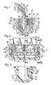
- the fastening device 11 according to the invention shown in the drawing in an exemplary embodiment serves for the length-adjustable fastening of foot straps 12 to surfboards and can also be used as a safety device in such a way that at least one end of the foot strap can be detachably fastened in the surfboard, in such a way that the relevant foot loop end is pulled out of the surfboard when a maximum tensile load that can be adjusted is exceeded.
- the fastening device 11 according to the invention is provided with an adjustable trigger mechanism 15.
- Fastening devices 11 of this type consist, apart from the foot strap band 16, of normally two pots 13 which are let into the surfboard at a distance from one another and are optionally welded or cast into which the ends 14 of the Foot strap band 16 are threaded.
- the area of the foot strap band 16 between the potties 13 is surrounded in a manner not shown here by a soft foam sleeve.
- the potty 13 of the fastening device 11 has an essentially U-shape in both mutually perpendicular cutting directions, the inner recess 17 being provided with a smooth wall except for two endings or thickenings 19.
- the outer circumference is provided with various projections and indentations and a peripheral edge 20.
- the potty 13, which is approximately symmetrical with respect to its transverse central plane 25, has an approximately oblong, rectangular basic shape.
- the projections 19 are arranged on the narrow walls 24 on one side, that is to say asymmetrically, with respect to the longitudinal center plane 18 and extend from the bottom 22 to close to the surface of the potty 13.
- each projection 19 is provided with a bore 23 which penetrates the narrow wall 24 and which can also be designed as a blind bore from the inside. Perpendicular to the bore 23, each projection 19 is provided with an insertion bevel 28 which runs from the top towards the bottom 22 and which, as shown in particular in FIG. 3, is channel-shaped, the diameter of the channel being from the top down to the bore 23 becomes smaller (corresponding to a conic section). In this way there is both an introductory slope and a centering.
- each end 14 of the foot strap band 16 is fastened in a length-adjustable manner to a one-piece insert part 30 made of plastic and provided with the adjustable trigger mechanism 15.
- the insert part 30 has a U-shaped resilient bracket 33 and a clasp 35 which are arranged parallel to one another and which are connected to one another on their upper side, preferably in one piece, via webs running parallel to the narrow walls 24, such that an elongated rectangular recess is formed 29 for the entry and exit of the foot strap end 14 is formed.
- the U-shaped bracket 33 has an upper flat, plate-like connecting leg 36 which runs parallel to the spaced lower shoulder legs 34, which are connected to the connecting leg 36 via vertical lateral parallel legs 32.
- the mutually facing extension legs 34 have inner free ends which are at a distance from one another and are chamfered in such a way that their clear distance to the connecting leg 36 is reduced.
- the shoulder legs 34 are provided with coaxial bearing journals 31 projecting perpendicularly with respect to the legs 32, which are circular in section and have a spherical cap shape at their free end.
- the clear distance between the outer sides of the legs 32 corresponds approximately to the clear distance between the inner surfaces of the inner formations 19 provided on the potty 13.
- the outer diameter of the bearing pins 31 is somewhat smaller than the inner diameter of the bores 23 in the potty 13.
- an eye 38 is formed on the underside of the connecting leg 36 and is provided with a continuous threaded bore 37 running perpendicular to the connecting leg 36, into which an adjusting screw 40 engages.
- the set screw 40 is screwed in such that its flat head 39, which is provided with a screwdriver slot, points towards the shoulder legs 34.
- the diameter of the head 39 is larger than the upper narrow clear distance facing between the two opposite ends of the shoulder legs 34, so that the adjusting screw head 39 can come to rest on these ends of the shoulder legs 34.
- the other end of the set screw 40 is also provided with a screwdriver slot, but is held retractable in the threaded bore 37.
- the bracket 33 formed in one piece from plastic is resiliently elastic in such a way that the projections 34 can be pushed together and apart.
- the clasp 35 has a lower longitudinal axis 51 and an upper parallel counter-holder 52, which is offset from the axis 51 in such a way that the counter-holder 52 forms the outside, while the axis 51 faces the U-shaped bracket 33.
- Axle 51 and counter-holder 52 of the one-piece clasp 35 made of plastic are connected to each other at their ends via a web 53.
- the axis 51 is approximately asymmetrically trapezoidal in cross-section, the one inclined surface pointing outwards
- the counter-holder 52 is approximately oblong in cross-section, its long side pointing from top to bottom.
- the underside of the axis 51 is arranged approximately at the level of the underside of the shoulder legs 34 of the U-bracket 33 and the top of the counter-holder 52 approximately at the level of the top of the U-bracket 33.
- the foot strap band 16 is made in one piece from plastic, preferably injection molded.
- the foot strap band 16 has a smooth outer surface 41 and in the region of the two ends 14 an inner surface 44 provided with parallel rib-shaped webs 46.
- the rib-shaped webs 46 run over the entire width of the foot strap band 16, are arranged parallel to one another at a certain distance and preferably only over one Length range of the foot strap end 14, which is determined by the size of the adjustment of the foot strap 12, is provided.
- the rib-shaped webs 46 which are opposite after the foot strap band 16 has been threaded into the insert part 30, can engage behind one another on the inner surfaces 44 and thereby get caught.
- the relevant end 14 of the foot strap band 16 is threaded into the insert part 30 such that the free end area 41 of the end of the foot strap 14 between the axis 51 and the counter-holder 52 of the clasp 35 and through the recess 29 in the insert part 30, and the incoming area 43 of the foot strap 16 is likewise through the recess 29 in the insert 30 and on the inside of the U-bar 33 inserted and guided over a loop or bend region 45 below the axis 51 of the clasp 35 near the bottom 22 of the potty 13.
- the rib-shaped webs 46 facing one another can get caught in the longitudinal direction of the foot strap band 16 or interlock.
- the return of the end region 41 below the arriving foot strap band region 43 in the opposite direction thereof and the elastic bending of the end region 41 opposite to the arriving region 43 simultaneously cause the arriving foot loop band region 43 to be pushed outwards, that is to say in a direction facing away from the opposite potty 13 that an approximately vertical entry and exit of the foot strap band 16 is effected as far as possible with respect to the surface of the potty 13 or the surfboard.
- the length adjustment of the foot strap band 16 can be carried out in stages in accordance with the selected spacing of the rib-shaped webs 46.
- the insert part 30 can be inserted or clipped into the potty 13. This takes place in such a way that the set screw 40 is first unscrewed in such a way that the screw head 39 is as far as possible from the shoulder legs 34. This makes it possible for the shoulder limbs 34 to be bent inwardly hanging on the legs 32 under the action of the insertion bevel 28 via the bearing pins 31, the bearing pins 31 being resiliently resilient (through the legs 32) into the bores 23 of the end of this movement Potty 13 snap in. If the adjusting screw 40 is no longer adjusted, the insert part 30 can be pulled out again at any time by hand. By screwing in the adjusting screw 40, i.e.
- the force is set which is necessary to pull the insert part 30 out of the potty again, since it is necessary to release the insert part 30 from the potty 13, that the shoulder leg 34 move inwards and towards the connecting leg 36. If the free ends of the shoulder legs 34 come into contact with the adjusting screw head 39, then a movement to release the bearing pins 31 from the bores 23 can only take place in their longitudinal direction and not also additionally in their transverse direction, which means a considerably greater expenditure of force. In this way, the maximum pulling force to be used to pull out the foot loop band end 14 in question with the relevant insert part 30 can be adjusted from the potty.
- this trigger mechanism 15 can moreover be completely blocked, so that the foot strap end in question, as in the previously known devices, is rigidly locked in the potty, that is to say it cannot be released.
- This is done according to FIG. 2 in such a way that the set screw 40 is first brought completely into contact with the head 39 on the inner surface of the extension leg 34 and that the set screw 40 is then screwed in further, so that the extension leg 34 is in a direction opposite to it Pull-out movement are biased, as indicated by dash-dotted lines in FIG.
- the journals 31 are fully inserted into the bores 23 and the outer sides of the shoulder legs 34 and the leg 32 are pressed against the inner surfaces of the shoulders 19 in the potty 13. In this way, a complete locking of the insert part 30 in the potty 13 is achieved.
Landscapes
- Chemical & Material Sciences (AREA)
- Engineering & Computer Science (AREA)
- Combustion & Propulsion (AREA)
- Mechanical Engineering (AREA)
- Ocean & Marine Engineering (AREA)
- Buckles (AREA)
- Purses, Travelling Bags, Baskets, Or Suitcases (AREA)
Claims (15)
Priority Applications (1)
| Application Number | Priority Date | Filing Date | Title |
|---|---|---|---|
| AT82108065T ATE14100T1 (de) | 1981-09-09 | 1982-09-02 | Vorrichtung zum befestigen von fussschlaufen an surfbrettern. |
Applications Claiming Priority (4)
| Application Number | Priority Date | Filing Date | Title |
|---|---|---|---|
| DE3135656 | 1981-09-09 | ||
| DE3135656 | 1981-09-09 | ||
| DE3206159 | 1982-02-20 | ||
| DE19823206159 DE3206159A1 (de) | 1981-09-09 | 1982-02-20 | Vorrichtung zum befestigen von fussschlaufen an surfbrettern |
Publications (2)
| Publication Number | Publication Date |
|---|---|
| EP0074087A1 EP0074087A1 (fr) | 1983-03-16 |
| EP0074087B1 true EP0074087B1 (fr) | 1985-07-03 |
Family
ID=25795880
Family Applications (1)
| Application Number | Title | Priority Date | Filing Date |
|---|---|---|---|
| EP82108065A Expired EP0074087B1 (fr) | 1981-09-09 | 1982-09-02 | Dispositif pour le raccordement des sangles de pieds aux planches à voile |
Country Status (2)
| Country | Link |
|---|---|
| EP (1) | EP0074087B1 (fr) |
| DE (2) | DE3206159A1 (fr) |
Families Citing this family (1)
| Publication number | Priority date | Publication date | Assignee | Title |
|---|---|---|---|---|
| FR2619783B1 (fr) * | 1987-08-28 | 1990-07-20 | Look Sa | Dispositif de securite pour cale-pied de planche a voile ou analogue |
Family Cites Families (3)
| Publication number | Priority date | Publication date | Assignee | Title |
|---|---|---|---|---|
| DE8001246U1 (de) * | 1980-05-08 | S.A.N. Warenvertriebs-Gmbh, 7107 Neckarsulm | Fußschlaufe für ein Segelbrett | |
| DE2945235C2 (de) * | 1979-11-09 | 1982-07-08 | Mistral Windsurfing AG, 8303 Nürensdorf, Zürich | Fußschlaufe für ein Segelbrett |
| DE3040764A1 (de) * | 1980-10-29 | 1982-05-27 | Marker, Hannes, 8100 Garmisch-Partenkirchen | Segelbrett mit fussschlaufen |
-
1982
- 1982-02-20 DE DE19823206159 patent/DE3206159A1/de not_active Withdrawn
- 1982-09-02 EP EP82108065A patent/EP0074087B1/fr not_active Expired
- 1982-09-02 DE DE8282108065T patent/DE3264562D1/de not_active Expired
Also Published As
| Publication number | Publication date |
|---|---|
| EP0074087A1 (fr) | 1983-03-16 |
| DE3264562D1 (en) | 1985-08-08 |
| DE3206159A1 (de) | 1983-03-17 |
Similar Documents
| Publication | Publication Date | Title |
|---|---|---|
| DE69302858T2 (de) | Seilklemme | |
| DE69903108T2 (de) | Seilklemme mit Vorspannung | |
| DE2612030A1 (de) | Verstelleinrichtung zur laengenverstellung eines gurtes oder dergleichen | |
| DE1903372C3 (de) | Halteschelle für Rohre, Kabel und dergl | |
| DE8212359U1 (de) | Vorrichtung zum verankern eines sitzgurtes | |
| DE1275814B (de) | Verschluss-Schnalle fuer Sicherheitsgurte od. dgl. | |
| DE3139424A1 (de) | Stellschnalle fuer gurte oder dergleichen | |
| DE20219461U1 (de) | Stockgriff mit Handschlaufe | |
| DE1429912A1 (de) | Behaelter mit loesbarem Griff | |
| DE19829332B4 (de) | Gurthalter | |
| DE4129299C2 (de) | Befestigungsorgan für Heizkörper | |
| DE20217375U1 (de) | Schnappverbinder, insbesondere für Pferdehalfter und Führleinen von Tieren | |
| DE2624453A1 (de) | Montageplatte fuer moebelscharniere | |
| DE2321814A1 (de) | Schlauchklemme | |
| DE2228127B2 (de) | Umlenkbeschlag fuer sicherheitsgurte | |
| WO1998002332A1 (fr) | Dispositif d'arrimage integre dans les parois de la carrosserie de poids-lourds | |
| EP0074087A1 (fr) | Dispositif pour le raccordement des sangles de pieds aux planches à voile | |
| DE102021125067B4 (de) | Ausstoßer für eine Umreifungsmaschine | |
| DE3049066A1 (de) | Kabelband aus flexiblem, hartelastischem kunststoff | |
| DE69019681T2 (de) | Befestigungsvorrichtung, bestehend aus Kabeln oder Stangen. | |
| DE3223041C2 (fr) | ||
| AT509610B1 (de) | Verstellvorrichtung, insbesondere längenverstellvorrichtung | |
| DE20114396U1 (de) | Stockgriff mit einstellbarer Handschlaufe | |
| DE3104907C2 (de) | Umlenkbeschlag für Dreipunkt-Sicherheitsgurt mit Gurtaufroller | |
| DE2753666A1 (de) | Beschlag fuer seile oder gurte, insbesondere abschleppseile- oder gurte |
Legal Events
| Date | Code | Title | Description |
|---|---|---|---|
| PUAI | Public reference made under article 153(3) epc to a published international application that has entered the european phase |
Free format text: ORIGINAL CODE: 0009012 |
|
| AK | Designated contracting states |
Designated state(s): AT BE CH DE FR GB IT LI LU NL SE |
|
| 17P | Request for examination filed |
Effective date: 19830416 |
|
| GRAA | (expected) grant |
Free format text: ORIGINAL CODE: 0009210 |
|
| AK | Designated contracting states |
Designated state(s): AT BE CH DE FR GB IT LI LU NL SE |
|
| PG25 | Lapsed in a contracting state [announced via postgrant information from national office to epo] |
Ref country code: NL Effective date: 19850703 Ref country code: IT Free format text: LAPSE BECAUSE OF FAILURE TO SUBMIT A TRANSLATION OF THE DESCRIPTION OR TO PAY THE FEE WITHIN THE PRESCRIBED TIME-LIMIT;WARNING: LAPSES OF ITALIAN PATENTS WITH EFFECTIVE DATE BEFORE 2007 MAY HAVE OCCURRED AT ANY TIME BEFORE 2007. THE CORRECT EFFECTIVE DATE MAY BE DIFFERENT FROM THE ONE RECORDED. Effective date: 19850703 Ref country code: BE Effective date: 19850703 |
|
| REF | Corresponds to: |
Ref document number: 14100 Country of ref document: AT Date of ref document: 19850715 Kind code of ref document: T |
|
| PG25 | Lapsed in a contracting state [announced via postgrant information from national office to epo] |
Ref country code: SE Effective date: 19850730 |
|
| REF | Corresponds to: |
Ref document number: 3264562 Country of ref document: DE Date of ref document: 19850808 |
|
| ET | Fr: translation filed | ||
| PG25 | Lapsed in a contracting state [announced via postgrant information from national office to epo] |
Ref country code: LU Free format text: LAPSE BECAUSE OF NON-PAYMENT OF DUE FEES Effective date: 19850930 |
|
| NLV1 | Nl: lapsed or annulled due to failure to fulfill the requirements of art. 29p and 29m of the patents act | ||
| PLBE | No opposition filed within time limit |
Free format text: ORIGINAL CODE: 0009261 |
|
| STAA | Information on the status of an ep patent application or granted ep patent |
Free format text: STATUS: NO OPPOSITION FILED WITHIN TIME LIMIT |
|
| 26N | No opposition filed | ||
| PGFP | Annual fee paid to national office [announced via postgrant information from national office to epo] |
Ref country code: AT Payment date: 19860924 Year of fee payment: 5 |
|
| PG25 | Lapsed in a contracting state [announced via postgrant information from national office to epo] |
Ref country code: GB Effective date: 19890902 Ref country code: AT Effective date: 19890902 |
|
| PG25 | Lapsed in a contracting state [announced via postgrant information from national office to epo] |
Ref country code: LI Effective date: 19890930 Ref country code: CH Effective date: 19890930 |
|
| GBPC | Gb: european patent ceased through non-payment of renewal fee | ||
| PG25 | Lapsed in a contracting state [announced via postgrant information from national office to epo] |
Ref country code: FR Effective date: 19900531 |
|
| REG | Reference to a national code |
Ref country code: CH Ref legal event code: PL |
|
| PG25 | Lapsed in a contracting state [announced via postgrant information from national office to epo] |
Ref country code: DE Effective date: 19900601 |
|
| REG | Reference to a national code |
Ref country code: FR Ref legal event code: ST |