EP0074094A2 - Dispositif d'équilibrage pour une raquette de tennis - Google Patents
Dispositif d'équilibrage pour une raquette de tennis Download PDFInfo
- Publication number
- EP0074094A2 EP0074094A2 EP82108115A EP82108115A EP0074094A2 EP 0074094 A2 EP0074094 A2 EP 0074094A2 EP 82108115 A EP82108115 A EP 82108115A EP 82108115 A EP82108115 A EP 82108115A EP 0074094 A2 EP0074094 A2 EP 0074094A2
- Authority
- EP
- European Patent Office
- Prior art keywords
- mass
- frame
- shaft
- rope
- handle
- Prior art date
- Legal status (The legal status is an assumption and is not a legal conclusion. Google has not performed a legal analysis and makes no representation as to the accuracy of the status listed.)
- Withdrawn
Links
Images


Classifications
-
- A—HUMAN NECESSITIES
- A63—SPORTS; GAMES; AMUSEMENTS
- A63B—APPARATUS FOR PHYSICAL TRAINING, GYMNASTICS, SWIMMING, CLIMBING, OR FENCING; BALL GAMES; TRAINING EQUIPMENT
- A63B60/00—Details or accessories of golf clubs, bats, rackets or the like
- A63B60/02—Ballast means for adjusting the centre of mass
Definitions
- the invention relates to a weight compensation device for a ball hitting device according to the preamble of patent claim 1.
- the conventional rackets with a center of gravity determined by the manufacture also do not allow the tactics to be changed from the net to the baseline game and vice versa during a match. The player is then forced to change the racket, and getting used to a different racket presents technical problems.
- the spindle is rotated by means of a rotary knob which is attached to the pin of the threaded spindle which protrudes at the end of the handle.
- the bearing of the threaded spindle in the shaft is structurally relatively complex.
- the arrangement of the threaded spindle in the shaft increases the overall racket weight, unless you save on the rest of the weight due to weaker dimensions.
- the weaker dimensioning (of the wall thicknesses) of the racket frame has a stability-reducing effect, so that there is an increased risk of breakage if the individual load is too high (for example a blow into the floor) or if there is a long-term load.
- the vibration behavior of the racket is adversely affected by the arrangement of the threaded spindle in the shaft.
- the known solution can also be used in a meaningful manner only in the case of a racket with a closed heart or a shaft reaching up to the head.
- US Pat. No. 2,546,140 also proposes attaching one or more adjustment weights which can be displaced along the same to the shaft.
- the user is able to change the center of gravity of the racket, if necessary, even during a play break, but this again requires a hand tool (screwdriver). Otherwise, the adjustment weights freely accessible from the outside are not very attractive.
- the opponent can very easily see whether a head-heavy and therefore preferably long balls or a handle-heavy and therefore preferably a volleyball stick is used.
- the object of the present invention is to improve the known construction in such a way that the mass changing the center of gravity of the ball striking device can be changed in position without difficulty even during a game.
- the solution according to the invention has the advantage that it is always ready for operation.
- the mass changing the center of gravity of the ball striking device can easily be changed in position even during a game, while at the same time ensuring that the opponent cannot easily recognize the set position of the center of gravity.
- the rope carrying the mass is provided with markings, preferably color markings, which can be recognized from the outside through a window provided in the frame or when the rope is deflected over the curved surface or pulley and indicate at which location the Mass relative to Center of gravity of the ball striker provided without adjusting mass is.
- the mass arranged on the endless rope is preferably divided into several partial masses which are attached to the rope at the same or different distances from one another. This enables an even finer adjustment of the center of gravity.
- the rope carrying the mass is preferably made of rubber or similar elastic plastic and is arranged under a predetermined tension in the frame interior.
- the invention also proposes the mass, the rope and / or the inside walls of the hollow frame, in particular the shaft, with a vibration-damping or shock-absorbing device Element.
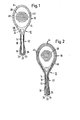
- the frame 12 of the tennis racket shown schematically in FIG. 1 consists of a head 16, a shaft 22 and a handle 18.
- the transition between head 16 and shaft 22 is formed by an open heart 24.
- the striking surface 28 is a conventional string covering.
- the frame 12 is hollow both in the shaft and in the heart and head area.
- a continuous endless rope 14 is arranged in such a way that it is guided around the head 16 of the racket and around a pulley 20 which is rotatably mounted in the area of the handle 18 about an axis 26 extending perpendicularly to the longitudinal direction of the shaft and the striking surface 28.
- the grooved disc 20 is mounted on the free end of the handle 18 so that it projects with part of its circumference over the end face of the handle 18.
- the circumferential surface of the grooved disk 20 is knurled so that it can be twisted slightly by the player's thumb or the like, and thus a mass 10 fastened to the cable 14 with a weight of about 5-50 p, preferably in the interior of the frame 12, can be displaced.
- the head 16 of the frame 12 is penetrated by a multiplicity of sleeves 40 which extend in the striking surface and through which the strings of the covering are pulled.
- the rope 14 is guided laterally past these sleeves within the head 16.
- a stop 38 for the mass 10 is provided in the shoulder area of the frame 12.
- the mass 10 can therefore only be displaced between the stop 38 on the one hand and the pulley 20.
- mass 10 is displaced into the area of the heart 24 or into the shoulder area 42, a tilting moment about the longitudinal axis of the shaft is additionally achieved. This tilting moment is of course hardly noticeable, but can have a positive effect if so-called topspin strokes are preferred.
- the stop 38 is omitted, the mass 10 can be displaced around the entire head 16 and along the entire shaft 22.
- the mass 10 is then preferably rounded at the ends or in the area of the connection to the cable 14, so that it cannot get caught on the sleeves 40.
- the mass 10 advantageously has the shape of an ellipsoid, the larger axis extending in the longitudinal direction of the rope.
- the embodiment according to FIG. 2 differs from that according to FIG. 1 essentially only in that the frame 12 is made from a hardened plastic tube 44, this hollow cylindrical tube 44 forming the core of the otherwise foamed frame 12 (foam jacket 46).
- the rope 14 is passed through the hardened plastic tube 44, in the area of the head 16, of course, past the sleeves 40 already mentioned laterally. Otherwise, the mechanism is the same as in the embodiment according to FIG. 1.
- color markings 34 are provided on the outside of the rope, which are visible from the outside when the rope 14 is deflected via the pulley 20 protruding beyond the end face of the handle 18. These markings 34 indicate the position of the mass 10 influencing the overall center of gravity of the tennis racket.
- the rope 14 carrying the mass influencing the center of gravity is one in the area of the handle 18 and one in the transition area between the head 16 and the shaft 22 or in the heart 24 of the frame 12 in each case one perpendicular to the longitudinal direction of the shaft and the striking surface 28 extending axis rotatably mounted grooved pulley (pulleys 47, 48).
- the movement of the rope 14 takes place via a handle connected to the axis of the pulley 48, e.g. Knurled wheel or wing nut.
- the axle is led out on one side of the frame 12 and with e.g. a knurled wheel rotatably connected.
- a window 32 is provided in the shaft 22, through which the cable 14 with corresponding markings for the position of the mass 10 is visible. 6, the window 32 is shown on an enlarged scale.
- the marking 36 provided on the cable 14 is formed by a rectangular two-color field, the two color areas 36 'and 36 "being separated from one another by a diagonal line 37.
- the color area 36' is kept darker (for example red) than the color area 36 "(e.g. yellow).
- the mass 10 can e.g. be arranged on the rope 14 such that when predominantly "red" becomes visible, the overall center of gravity is shifted towards the handle and vice versa.
- the color marking can of course also be formed by horizontal stripes or the like.
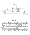
- FIGS. 4 and 5 is a tennis racket with two endless ropes 14 ', 14 "which run around the inside of the frame and can be driven from the outside, each of which has a mass 10 'or 10 "is attached.
- the cross sections of the cables 14 ', 14 "each have the shape of an isosceles triangle, the tip being on the inside.
- a large contact area" cable groove "of the pulley 20 or 20 'received As can be seen in FIG. 5, the cross sections of the cables 14 ', 14 "each have the shape of an isosceles triangle, the tip being on the inside.
- the rope 14 or the ropes 14 ', 14 can also be designed as so-called toothed belts corresponding to a toothed belt. Flat belts are also possible.
- Embodiments are also conceivable which comprise more than two cables carrying mass.
- a set of ropes could e.g. for larger masses (rough adjustment of the balance point) and the other set of ropes for smaller masses (fine adjustment or readjustment of the balance point).
- the device designed according to the invention for transferring a mass that influences the center of gravity can be used both for tennis rackets and for squash, badminton or similar rackets.
- rackets must all be hollow. They preferably consist of a hollow profile made of plastic or light metal, for example aluminum.
- a ribbon ug to Z and strainable pressure can be used, whose free end is provided with a mass body corresponding to the mass 10, and this is again unwound wound onto a forth drivable from outside the drum and from this, whereby the mass body or the mass 10 is displaceable in the longitudinal direction of the frame.
- the drum for the flat belt is preferably rotatably mounted about the above-mentioned axis 26 for the pulley 20. Clamping elements cooperating with the drum are provided for locking the flat band or the mass. These can also be operated from the outside.
- the clamping mechanism preferably has a clamping screw which can be screwed against the pulley or the rope.
- the described pulley can finally be replaced in a simple version by a smooth polished curved surface over which the cable 14 is guided.
- This surface preferably also has a guide groove or groove for the cable, such that the cable protrudes slightly above the surface of the surface in order to be able to be moved or displaced by means of the thumb or the like.
- the mass 10 (preferably a lead or stainless steel weight) is used to suppress transversal or transverse vibrations of the rope 14 and / or the mass 10 in the interior of the frame 12 or shaft 22, which produce knocking or rattling noises.
- a relatively thin plastic sheathing 56 on the long sides of which, or on the sides extending parallel to the longitudinal direction of the shaft, molded-on spacers protruding outward like spikes in the form of elastically flexible feet or tabs 58.
- the damping element designed in this way is identified in FIG. 7 by the reference number 51.
- the feet or tabs 58 are dimensioned (length and diameter) so that the mass 10 within the frame or.
- the inside of the shaft is kept free of vibrations and centered. At the same time, the free movement of the mass 10 in the longitudinal direction of the shaft should not be impeded by the damping feet 58.
- the thickness of the plastic sheath 56 is approximately 0.4 to 1.0 mm
- the diameter of the damping feet 58 is approximately 0. 4 to 1.0 mm and the length of the damping feet 58 between 4 and 10 mm.
- these dimensions also depend on the free cross-section of the frame or.
- the plastic sheath 56 is preferably connected in one piece to the cable 14, specifically to the part which is guided around the deflection roller 20.
- an eyelet 68 is provided, to which a thin but tear-resistant silk (fishing line) can be attached as a continuation of the drawstring.
- the free end of the part of the cable 14 which is integrally connected to the plastic sheathing 56 is also provided with an eyelet 72 to which the other end of the silk 70 can be fastened, so that an endless one Drive rope for mass 10 is created.
- a cable damping element 54 is provided, consisting of spacers 60 protruding outward in the manner of spikes in the form of elastic, flexible feet or rags, which are preferably molded onto the cable 14.
- the sheathing of the mass 10 with the damping element 51, the damping element 54 and the intermediate part of the cable 14 with a preferably triangular cross section can be produced by plastic injection molding in a single operation.
- the sections of the cable 14 adjacent to the deflection roller 20 are of course free of damping elements of the type described, in order not to hinder the deflection and movement of the cable 14 by a predetermined distance.
- FIG. 8 shows an embodiment in which additional damping elements 52 are provided on the inside of the shaft wall 67.
- damping elements are by mutually spaced-apart, projecting into the interior of shaft elastically flexible Schockabsorber- or D ämpflappen 66 formed, which are held in openings 74 of the frame wall 67th
- the damping flaps 66 each have a neck-like constriction, so that they can be snapped into the wall openings 74 from the outside.
- the length of the damping flap 66 is such that its in the frame or.
- the ends of the shaft projecting inside the shaft always lie against the rope in order to prevent transverse vibrations from occurring in the first place.
- the damping flaps 66 extend approximately transversely to the longitudinal direction of the shaft almost over the entire clear width of the frame or shaft interior, the openings 74 in the frame or.
- Shaft wall 67 are correspondingly slit-like.
- the openings 74 are located in the plane formed by the two runs of the cable 14 (upper and lower run) or defined by the deflection roller 20.
- damping flaps 66 can be arranged in the immediate vicinity of the deflection roller 20, so that vibration damping is practically possible over the entire length of the endless cable 14.
- FIGS. 9 and 10 An advantageous modification of the embodiment according to FIG. 8 is shown in FIGS. 9 and 10.
- the damping elements 52 provided on the inside of the frame or shaft 22 are formed by so-called "hedgehog belts", each consisting of a strip 62 made of plastic or the like which can be fastened to the inside of the frame or shaft 22 and molded onto it in the frame. or spacer 64 protruding from the inside of the shaft in the form of elastically flexible feet.
- the hedgehog belts are designed in the manner of a brush, the bristles of which protrude into the frame interior and suppress transverse vibrations of the mass 10 and of the drive belt 14.
- the hedgehog tapes are preferably fixed in the interior of the frame or shaft by gluing the base strip 62 to the inside of the frame or shaft wall.
- two hedgehog tapes are provided, which extend over almost the entire length of the shaft and are glued diametrically inside the shaft, in such a way that their elastically flexible damping feet 64 are parallel to that formed by the two strands or the Deflection roller 20 defined level.
- the spacers mentioned in the form of flexible feet have both a centering and shock and vibration absorbing function, the vibration energy being converted into deformation and friction energy. At the same time, they in no way hinder the free mobility of the rope 14 and the mass 10 in the longitudinal direction of the frame or shaft.
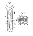
- 11 to 13 are particularly advantageous constructive embodiments for a weight balancing device with the features of the invention are shown schematically in terms of production technology and on-site technology.
- the cable 14 including the center of gravity-changing mass 10 and curved surfaces (pulleys 47, 48 and 20, 86) is located in a mounting sleeve 76 or in the shaft 22 of the racket 78.
- the mounting sleeve 76 is formed by two receiving or guide tubes 90, 92 for the cable 14 and the mass 10, which are connected to one another by a central web 88, on their two outer sides opposite the central web 88 are each slotted.
- the mounting sleeve is preferably made of plastic and is inserted in the shaft 22 against the inner walls.
- the mounting sleeve 76 is fixed in the interior of the shaft by means of one or more fixing screws, which are indicated in FIG. 11 with the reference numbers 94.96.
- grooved washers 47, 48 are rotatably supported, the lower grooved washer 47 in FIG. 11 protruding beyond the end face of the free shaft end for the reasons mentioned above.
- the rope 14 is guided around the two pulleys 47, 48.
- a multiplicity of damping feet or bristles 64 protrude inwards from the inner sides of the two guide tubes 90, 92, the bristles 64 preferably being connected in one piece to the two guide tubes 90, 92 or the mounting sleeve 76 .
- the bristles 64 are dimensioned such that they center the mass 10 and the cable 14 within the guide tubes 90, 92 on the one hand and Suppress transverse vibrations of the mass 10 or of the rope 14, but on the other hand oppose a movement of the rope 14 and thus the displacement of the mass 10 in the longitudinal direction of the shaft to a minimal frictional resistance.
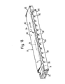
- the mounting sleeve 78 has a rectangular cross section, the upper side wall 80 of the sleeve 78 being mounted so as to be displaceable relative to the other side walls in the sleeve longitudinal and sleeve transverse directions 82 and 84, respectively, in such a way that it counteracts the action of an elastic one Biasing can be brought from a position clamping the mass 10 into a position releasing the mass 10.
- the mass 10 is released in the illustration in FIG. 13 by moving the upper side wall 80 to the right. Then the mass 10 can be moved into the desired position by rotating the grooved disk 20.
- the mounting sleeve 78 is arranged in the interior of the shaft so that the grooved disk 20 protrudes slightly beyond the end face at the free shaft end or free handle end.
- two deflection rollers 86 for the cable 14 are rotatably mounted on the underside or inside of the upper side wall 80 at the end opposite the pulley 20, with the result that in this way the elastic preload mentioned by a certain amount Rope 14 exhibiting inherent elasticity takes place.
- the cable 14 is stretched by moving the upper side wall 80 to the right and upwards. At the same time, however, the clamping effect of the upper side wall 80 on the mass 10 and the rope 14 is canceled, so that the mass 10 can be easily displaced by rotating the pulley 20. If the upper side wall 80 is then released again, the stretched rope 14 pulls the upper side wall 80 back into its clamping position, namely to the left and down in FIG. 13.
- the superimposed movement of the upper side wall 80 in the direction of arrows 82 and 84 is indicated by corresponding storage of the upper side wall 80 in the two upright side walls of the mounting sleeve 78 is achieved.
- the two upright side walls of the M ontagehülse 78 for example, a plurality of obliquely directed cuts or slits 98 that project into the laterally protrudes from the upper side wall 80 guide pins 100th
- the incisions, viewed from the grooved disk 20, are directed obliquely upwards.
- the displacement or displacement of the upper side wall 80 is preferably carried out by the construction means described in claims 34 and 35.
- the measure according to claim 14 can also be provided. It can then be achieved at the same time that the mass and the rope are free of the clamping action of the side wall 80 and the rope is relatively relaxed to facilitate operation.
- the spring force acting directly on the axis of the grooved disk 20 is somewhat greater than the restoring force caused by the elongation of the cable 14.
- the cross section of the cable 14 can be chosen so that the three corners abut the inner sides of the two guide tubes 90, 92. In this case, the steaming bristles 64 are unnecessary. However, increased frictional resistance during the movement of the rope 14 must then be expected.
Landscapes
- Health & Medical Sciences (AREA)
- General Health & Medical Sciences (AREA)
- Physical Education & Sports Medicine (AREA)
- Golf Clubs (AREA)
Applications Claiming Priority (4)
| Application Number | Priority Date | Filing Date | Title |
|---|---|---|---|
| DE3135167A DE3135167C1 (de) | 1981-09-04 | 1981-09-04 | Gewichtsausgleichsvorrichtung für ein Ballschlaggerät |
| DE3135167 | 1981-09-04 | ||
| DE3207650 | 1982-03-03 | ||
| DE19823207650 DE3207650A1 (de) | 1981-09-04 | 1982-03-03 | Ballschlaggeraet, insbesondere tennis-, raquet- oder squash-schlaeger, mit veraenderbarem schwerpunkt |
Publications (2)
| Publication Number | Publication Date |
|---|---|
| EP0074094A2 true EP0074094A2 (fr) | 1983-03-16 |
| EP0074094A3 EP0074094A3 (en) | 1984-02-01 |
Family
ID=25795796
Family Applications (1)
| Application Number | Title | Priority Date | Filing Date |
|---|---|---|---|
| EP82108115A Withdrawn EP0074094A3 (en) | 1981-09-04 | 1982-09-02 | Balancing device for a tennis racket |
Country Status (4)
| Country | Link |
|---|---|
| EP (1) | EP0074094A3 (fr) |
| AU (1) | AU8802982A (fr) |
| BR (1) | BR8205207A (fr) |
| DE (1) | DE3207650A1 (fr) |
Cited By (5)
| Publication number | Priority date | Publication date | Assignee | Title |
|---|---|---|---|---|
| FR2569989A1 (fr) * | 1984-09-07 | 1986-03-14 | Dunlop Ltd | Raquette pour jouer |
| AT389054B (de) * | 1984-11-06 | 1989-10-10 | Head Sportgeraete Gmbh | Tennisracket |
| EP0473184A1 (fr) * | 1990-08-31 | 1992-03-04 | Wilson Sporting Goods Company | Raquette de squash |
| CN112337065A (zh) * | 2020-11-11 | 2021-02-09 | 华北水利水电大学 | 一种组装式网球拍 |
| US20230021604A1 (en) * | 2021-07-22 | 2023-01-26 | Wei-Jung Chen | Shock absorbing device |
Family Cites Families (9)
| Publication number | Priority date | Publication date | Assignee | Title |
|---|---|---|---|---|
| US2028291A (en) * | 1934-06-06 | 1936-01-21 | Macpherson Albert Alfred | Implement handle |
| US2215899A (en) * | 1938-10-29 | 1940-09-24 | Beasley Mercer | Removable weight and balance adjustments |
| US2395864A (en) * | 1941-04-01 | 1946-03-05 | Spalding A G & Bros Inc | Racket |
| FR2122089A5 (fr) * | 1971-01-13 | 1972-08-25 | Thibault Jacques | |
| US3801099A (en) * | 1971-06-23 | 1974-04-02 | J Lair | Tennis racquet |
| US3907292A (en) * | 1972-02-05 | 1975-09-23 | James P Moreland | Dynamically variable tennis racket |
| US3975018A (en) * | 1975-08-08 | 1976-08-17 | Walker Frank J | Racket construction |
| BE862860A (fr) * | 1978-01-12 | 1978-05-02 | Crahay Philippe | Raquette de tennis a centre de gravite reglable. |
| US4355803A (en) * | 1980-12-22 | 1982-10-26 | Coin-Operated Exercise Equipment Co. Inc. | Tennis racquet with variable center of gravity and balance |
-
1982
- 1982-03-03 DE DE19823207650 patent/DE3207650A1/de not_active Ceased
- 1982-09-02 EP EP82108115A patent/EP0074094A3/de not_active Withdrawn
- 1982-09-03 BR BR8205207A patent/BR8205207A/pt unknown
- 1982-09-06 AU AU88029/82A patent/AU8802982A/en not_active Abandoned
Cited By (5)
| Publication number | Priority date | Publication date | Assignee | Title |
|---|---|---|---|---|
| FR2569989A1 (fr) * | 1984-09-07 | 1986-03-14 | Dunlop Ltd | Raquette pour jouer |
| AT389054B (de) * | 1984-11-06 | 1989-10-10 | Head Sportgeraete Gmbh | Tennisracket |
| EP0473184A1 (fr) * | 1990-08-31 | 1992-03-04 | Wilson Sporting Goods Company | Raquette de squash |
| CN112337065A (zh) * | 2020-11-11 | 2021-02-09 | 华北水利水电大学 | 一种组装式网球拍 |
| US20230021604A1 (en) * | 2021-07-22 | 2023-01-26 | Wei-Jung Chen | Shock absorbing device |
Also Published As
| Publication number | Publication date |
|---|---|
| AU8802982A (en) | 1983-03-31 |
| BR8205207A (pt) | 1983-08-16 |
| EP0074094A3 (en) | 1984-02-01 |
| DE3207650A1 (de) | 1983-09-15 |
Similar Documents
| Publication | Publication Date | Title |
|---|---|---|
| EP0106850B1 (fr) | Raquette de tennis ou de squash | |
| DE3530481A1 (de) | Tennisuebungsgeraet | |
| DE4116062A1 (de) | Griffstueck fuer golfschlaeger | |
| EP0553769A1 (fr) | Raquette, en particulier raquette de tennis | |
| DE2656082A1 (de) | Tennisschlaeger | |
| DE3815376A1 (de) | Tennisschlaeger | |
| DE2902271A1 (de) | Fussballtrainingsgeraet | |
| EP0074094A2 (fr) | Dispositif d'équilibrage pour une raquette de tennis | |
| DE102011105609B4 (de) | Tragbares Sportgerät | |
| EP0210539A1 (fr) | Appareil pour jouer à la balle avec une parois de rebond fixée sur un support portatif | |
| DE2724652A1 (de) | Anordnung zur verbesserung bzw. veraenderung des spielverhaltens eines schlaegers fuer tennis oder aehnliche spiele | |
| DE10354068A1 (de) | Ballrückholvorrichtung für Ballspiele, insbesondere für Tennisschläger | |
| DE3702197C2 (de) | Tennisschläger | |
| DE3135167C1 (de) | Gewichtsausgleichsvorrichtung für ein Ballschlaggerät | |
| DE102021126574A1 (de) | Dämpfungsvorrichtung für einen Ballsportschläger und Ballsportschläger | |
| DE3152421A1 (de) | Gewichtsausgleichvorrichtung fuer ein ballschlaggeraet | |
| DE3211738A1 (de) | Tennisschlaeger | |
| DE3520335A1 (de) | Anordnung zur veraenderung bzw. einstellung des gewuenschten spielverhaltens eines schlaegers fuer tennis oder aehnliche spiele | |
| DE19725430C1 (de) | Ballschlaggerät, insbesondere Tennis-, Squash- oder Badminton-Schläger | |
| CH190183A (de) | Ballspiel. | |
| DE3826347A1 (de) | Handgehaltenes schlaggeraet fuer spiel- und sportzwecke | |
| DE29512494U1 (de) | Sportgerät zum Trainieren des menschlichen Körpers | |
| DE2628434A1 (de) | Ballschlaggeraet | |
| DE4100081A1 (de) | Verfahren zum einstellen der saitenspannung und spannvorrichtung fuer einen tennisschlaeger | |
| AT405788B (de) | Schläger od.dgl. für ballspiele |
Legal Events
| Date | Code | Title | Description |
|---|---|---|---|
| PUAI | Public reference made under article 153(3) epc to a published international application that has entered the european phase |
Free format text: ORIGINAL CODE: 0009012 |
|
| AK | Designated contracting states |
Designated state(s): AT BE CH DE FR GB IT LI LU NL SE |
|
| PUAL | Search report despatched |
Free format text: ORIGINAL CODE: 0009013 |
|
| AK | Designated contracting states |
Designated state(s): AT BE CH DE FR GB IT LI LU NL SE |
|
| STAA | Information on the status of an ep patent application or granted ep patent |
Free format text: STATUS: THE APPLICATION HAS BEEN WITHDRAWN |
|
| 18W | Application withdrawn |
Withdrawal date: 19840919 |
|
| RIN1 | Information on inventor provided before grant (corrected) |
Inventor name: PICHLER, OSWALD Inventor name: HIEBLINGER, RUDOLF |