EP0074097B1 - Antriebsvorrichtung für eine landwirtschaftlich nutzbare Maschine - Google Patents
Antriebsvorrichtung für eine landwirtschaftlich nutzbare Maschine Download PDFInfo
- Publication number
- EP0074097B1 EP0074097B1 EP19820108145 EP82108145A EP0074097B1 EP 0074097 B1 EP0074097 B1 EP 0074097B1 EP 19820108145 EP19820108145 EP 19820108145 EP 82108145 A EP82108145 A EP 82108145A EP 0074097 B1 EP0074097 B1 EP 0074097B1
- Authority
- EP
- European Patent Office
- Prior art keywords
- torque
- drive arrangement
- arrangement according
- traction means
- wheel
- Prior art date
- Legal status (The legal status is an assumption and is not a legal conclusion. Google has not performed a legal analysis and makes no representation as to the accuracy of the status listed.)
- Expired
Links
- 230000005540 biological transmission Effects 0.000 claims description 22
- 238000010008 shearing Methods 0.000 claims description 19
- 230000008878 coupling Effects 0.000 claims description 17
- 238000010168 coupling process Methods 0.000 claims description 17
- 238000005859 coupling reaction Methods 0.000 claims description 17
- 239000010902 straw Substances 0.000 claims description 5
- 238000005096 rolling process Methods 0.000 claims description 4
- 241000239290 Araneae Species 0.000 claims 9
- 230000007246 mechanism Effects 0.000 description 27
- 238000009434 installation Methods 0.000 description 3
- 238000000034 method Methods 0.000 description 3
- 230000008569 process Effects 0.000 description 3
- 208000015943 Coeliac disease Diseases 0.000 description 2
- 230000004308 accommodation Effects 0.000 description 2
- 238000012423 maintenance Methods 0.000 description 2
- 241001124569 Lycaenidae Species 0.000 description 1
- 230000009471 action Effects 0.000 description 1
- 230000015572 biosynthetic process Effects 0.000 description 1
- 238000006243 chemical reaction Methods 0.000 description 1
- 238000002485 combustion reaction Methods 0.000 description 1
- 238000006073 displacement reaction Methods 0.000 description 1
- 238000003780 insertion Methods 0.000 description 1
- 230000037431 insertion Effects 0.000 description 1
- 239000000314 lubricant Substances 0.000 description 1
- 239000000463 material Substances 0.000 description 1
- 210000000056 organ Anatomy 0.000 description 1
- 238000009527 percussion Methods 0.000 description 1
- 230000009467 reduction Effects 0.000 description 1
- 230000008439 repair process Effects 0.000 description 1
- 230000000284 resting effect Effects 0.000 description 1
- 125000006850 spacer group Chemical group 0.000 description 1
Images



Classifications
-
- A—HUMAN NECESSITIES
- A01—AGRICULTURE; FORESTRY; ANIMAL HUSBANDRY; HUNTING; TRAPPING; FISHING
- A01F—PROCESSING OF HARVESTED PRODUCE; HAY OR STRAW PRESSES; DEVICES FOR STORING AGRICULTURAL OR HORTICULTURAL PRODUCE
- A01F12/00—Parts or details of threshing apparatus
- A01F12/56—Driving mechanisms for the threshing parts
-
- A—HUMAN NECESSITIES
- A01—AGRICULTURE; FORESTRY; ANIMAL HUSBANDRY; HUNTING; TRAPPING; FISHING
- A01D—HARVESTING; MOWING
- A01D69/00—Driving mechanisms or parts thereof for harvesters or mowers
- A01D69/06—Gearings
-
- F—MECHANICAL ENGINEERING; LIGHTING; HEATING; WEAPONS; BLASTING
- F16—ENGINEERING ELEMENTS AND UNITS; GENERAL MEASURES FOR PRODUCING AND MAINTAINING EFFECTIVE FUNCTIONING OF MACHINES OR INSTALLATIONS; THERMAL INSULATION IN GENERAL
- F16H—GEARING
- F16H35/00—Gearings or mechanisms with other special functional features
- F16H35/10—Arrangements or devices for absorbing overload or preventing damage by overload
- F16H2035/103—Arrangements or devices for absorbing overload or preventing damage by overload with drive interruption by structural failure of overload preventing means, e.g. using shear pins
Definitions
- the invention relates to a drive device for an agricultural machine with a gear having at least two speed ranges, in particular planetary gear, which is integrated within a recess of a traction mechanism disc, which has a coupling element, e.g. a torque cross or a torque wheel is assigned, which is rotatably mounted for gear shifting on a shaft of the gear and one input part, e.g. defines an input sun gear, the gearbox on the housing of the machine and the other on the traction sheave.
- a coupling element e.g. a torque cross or a torque wheel
- a drive device for a combine harvester is already known (US-A-4 138 837), which has a continuously adjustable traction mechanism gear, the driven traction mechanism pulley of which is drive-connected to a planetary gear mechanism, which for this purpose has a shaft on which the traction mechanism pulley is also arranged.
- the planetary gear is located in the area of the front of the non-adjustable traction sheave and is housed in a special gear housing for this purpose.
- the planetary gear can be alternately set to two speed ranges using a complex control device.
- This actuating device has a switching cam which can be actuated via an axially adjustable linkage provided in the housing of the transmission.
- a threshing drum drive with a large control range for combine harvesters is also known (DE-A-2 354 440), a planetary gear being arranged outside the threshing drum wall on the threshing drum shaft, the housing circumference of which is designed to accommodate drive means and via a drive with constant transmission ratio of one steplessly adjustable gear arranged outside the area of the drive wheel can be driven.
- a plate washer is arranged between the threshing drum wall and the housing, which is connected to the planetary gear via a spur gear bushing, with the plate disc being selectively connected to the threshing drum wall or to the gearbox housing for gear shifting, preferably via an Allen screw and one on the threshing drum wall and on the plate disc arranged threaded bushing is connectable.
- the object of the invention is to design and arrange the drive device in such a way that, in addition to a space-saving arrangement, damage to the individual drive elements is avoided if an overload occurs.
- This object has been achieved in that a link designed as an overload protection device is provided between the coupling element and the housing and is connected to the coupling element or to the housing via a shear pin.
- a link designed as an overload protection device is provided between the coupling element and the housing and is connected to the coupling element or to the housing via a shear pin.
- the coupling element arranged on the shaft can rotate freely with the traction element disc without it colliding with the rotating parts of the traction element disc.
- the coupling element is designed as a torque cross, which is rotatably and fixably mounted on the shaft and is fixedly connected to the input part.
- the handlebar of the overload protection is articulated at one end to an actuating arm of the torque cross and at the other end directly or indirectly to a frame or to the housing of the machine. If an overload occurs at low speed and greater torque transmission, the shear pin provided between the link and the coupling element can be easily sheared off and the drive connection between the traction element disc and the planetary gear can be separated.
- the handlebar of the overload safety device is articulated to a linkage which is pivotably mounted on the frame of the machine and which, after being released from the handlebar via a spring, can be pivoted automatically into a position which does not impede the rotary movement of the torque cross. Since the torque arm can be fixed in a simple manner via the handlebar and the linkage on the housing of the machine, the handlebars and the linkage can be swiveled upwards immediately after the shear pin between the torque arm and the handlebar has been sheared off, so that no damage to the torque arm when turning further Handlebars and torque arm occurs.
- This drive device is particularly suitable for driving the threshing drum of a combine harvester and ensures that if the threshing drum is loaded too heavily with harvested material, the threshing drum is switched off automatically by the drive.
- the planetary gear is arranged in a housing which is part of the traction mechanism disc, the width of the planetary gear mechanism extending in the axial direction of the shaft roughly corresponding to the total width of the traction mechanism disc, which is arranged close to a side wall of the housing of the combine harvester . Due to the advantageous design and arrangement of the traction sheave, the planetary gear can be easily accommodated between the two end faces of the traction sheave, so that the space requirement for the traction sheave and the planetary gear can be kept relatively small, so that the traction sheave can be used for the central or direct drive of the threshing drum can easily be accommodated on the outside of the combine harvester.
- the planetary gear is formed from a first sun gear rotatably mounted on the shaft and a second sun gear rotatably mounted on the shaft and firmly connected to the torque cross, and a double planet gear which is connected via a planet carrier to the outside of the traction element disc, the first Sun gear is larger than the second sun gear, so that when the planetary gear is switched on for indirect drive, the speed of the shaft is lower than the speed of the traction sheave.
- a direct drive connection between the traction element disc and the shaft for driving the threshing drum can be established in a simple manner. Furthermore, it is possible to drive the shaft of the threshing drum much more slowly or faster than the traction means disc.
- the housing integrated in the traction element disc is formed from a disc ring, a side wall that is inside with respect to the side wall of the combine harvester and an outside side wall, the outside side wall being designed as a planet carrier that is detachably connected to the traction element disc via screw bolts is. It is also advantageous that in each side wall of the housing for receiving the planetary gear there is provided a roller bearing arranged coaxially to the shaft for rotatably receiving the traction element disk. It is also advantageous that the second sun gear has an axially extending hub for receiving the roller bearing arranged in the outer side wall.
- the input sun gear can be fixed in a simple manner with reference to the side wall or the frame of the combine harvester, so that the drive via the traction sheave takes place via the planetary gear and thereby the lower or Gear ratio between the planet gears and the sun gears can be used. Furthermore, the input sun gear can also be connected in a rotationally fixed manner to the traction mechanism disc via the torque arm, so that the planetary gear is switched off and the drive of the traction mechanism disc is directed directly onto the shaft.
- the drive connection between the traction means disc and the torque arm is released and this is also not fixed to the housing of the combine harvester, the drive connection between the traction means disc and the shaft for driving the threshing drum is interrupted.
- the torque cross is arranged on the hub of the second sun gear in a rotationally fixed manner.
- an actuating arm of the torque cross via a releasable connecting element e.g. a bolt, to which the traction mechanism disc can optionally be connected, which can be inserted into a recess provided on the actuating arm and into a recess on the traction mechanism disc that can be aligned with this.
- the coupling element consists of a torque cross with two radially extending adjusting arms, one arm having a recess optionally being connectable to the traction sheave disc and the other arm optionally being connectable to the housing of a combine harvester via the shear pin, the connection points of the Arms lie on radii of different sizes.
- a compact design for the traction device disc and the torque arm is obtained by the fact that the torque cross is arranged close to the outside of the traction device disc and that the traction device disc has two mutually parallel end faces which are at a distance from one another which is greater than the total width of the planetary gear.
- the drivable traction means disc has a disc part to which the drive is introduced and which can be connected non-rotatably to the shaft for a first drive speed, the input sun gear of the planetary gear for a second drive speed optionally with a threshing housing is directly or indirectly non-rotatably connectable.
- a second traction sheave is arranged on the shaft in addition to the drivable traction sheave and is connected to the shaft in a rotationally fixed manner, the first traction sheave being used for a connecting element, e.g.
- a plug-in connection which can optionally be connected to the non-rotatable traction means disc, or the torque wheel which is non-rotatably connected to the input sun gear can be connected indirectly or directly to a threshing housing via the same connecting element.
- a second traction sheave which is arranged next to the first traction sheave non-rotatably on the shaft, the first traction sheave can be easily connected to the shaft in a rotationally fixed manner, so that the drive introduced to the first traction sheave is directly connected to the shaft via the second traction sheave Shaft is guided so that the shaft and the two traction sheaves rotate at the same speed.
- first traction sheave For the rotationally fixed connection of the first traction sheave to the second traction sheave, only one connecting element is used, which can optionally establish a rotationally fixed connection between the two traction sheaves. If the drive connection between the two traction mechanism disks is to be broken, the same connecting element can also be used for the rotationally fixed connection of the input sun gear to the torque gear.
- the first traction element disc In order to be able to connect the first traction element disc to the second traction element disc in a simple manner, the latter has a flange which lies within the axial rotation of the disc part to which the drive is introduced. In this way, a very space-saving and space-saving arrangement of both traction center disks is obtained.
- the connecting element has at least one bolt, which can be inserted into a flange in the non-rotating traction sheave and into a hole provided in the first traction sheave, a rotationally fixed connection can be created in a very short time between the two traction sheaves without additional work tools being required.
- the on the hub of the Input sun gear arranged torque gear has a ring gear, to which a connecting piece having a connecting eye is connected by means of a shear bolt, which is provided with a groove which is placed on a rib provided on the outer circumference of the torque gear. If, for example, an overload occurs on the shaft or on the working tools, the drive connection between the traction sheave and the shaft can be interrupted in a simple manner by shearing off the shear pin, so that damage to the working elements is avoided.
- the torque wheel has a bore extending radially inwards from the outer circumference, into which the shear pin can be inserted, which is used for the detachable connection of a linkage having the connecting eye, which has one end pivotable about an axis on the combine harvester's frame is mounted, which runs parallel to the axis of the torque wheel, wherein the linkage can be pivoted away from the torque wheel after shearing off the shear pin via a spring connected to the linkage.
- a shear pin connection part is provided between the linkage and the torque wheel, which has on one end the connecting eye with a bore running parallel to the axis of the torque wheel for articulated connection of the linkage and on the other end the bore running radially to the axis of the torque wheel for receiving the shear pin which extends through the groove which can be placed on the rib, the connecting piece being connected to the torque wheel in the region of the upper point of the torque wheel running through a dead center position.
- the shear pin connection part Since the shear pin connection part is connected to the torque wheel with the linkage for fixing the input sun gear to the outer circumference, in the area of the upper or a dead center position of the torque wheel, the shear pin between the shear pin connection part and the first traction sheave is easily sheared off in the event of an overload and thus the drive connection is interrupted. At the same time, the handlebar with the shear pin connection part is swiveled back so far that there can be no collision with the traction sheave.
- a lever extending over the shear-side end of the linkage for pivoting the linkage against the action of a spring in the direction of the torque wheel is provided on the linkage, which, after the shear pin has been sheared off, by means of the spring a stop can be used so that the lever does not hinder a further rotation of the traction element disc.
- the lever thus facilitates a renewed coupling of the handlebar to the torque wheel even after loosening the connection between the handlebar and the torque wheel, since this can be pivoted towards the torque wheel with little effort. It is also advantageous that the shear surface against which the shear pin connecting part rests runs concentrically to the axis of the torque wheel.
- the radius of the shear surface of the shear pin connection part is larger than the radius of the ring gear.
- the traction means disc which is connected to the shaft in a rotationally fixed manner, serves to drive a straw guide drum. Since the outer surface of the torque wheel has a rib and the handlebar or the shear pin connection part is provided with a groove, the handlebar can be easily fixed to the side of the torque wheel, with the two holes in the torque wheel and on the connecting piece without being adjusted only slightly by the torque wheel further can be aligned to each other in order to insert the shear pin. Since the traction mechanism disc, which is connected to the shaft in a rotationally fixed manner, is used to drive the straw guide drum, depending on the type of drive, the straw guide drum is driven once faster or slower, as is the case when driving the threshing drum.
- 10 denotes a drive system for a threshing drum 11 (see dashed lines in FIG. 1), which in the region of the front end of the threshing housing 12 with the associated type Drive device 10 is added.
- a threshing drum 11 In Fig. 1 only the side walls 13 and 15 of the threshing housing are shown.
- the threshing drum 11 is located above a threshing basket 14 and is supported between the opposite side walls 13 and 15.
- the drive device 10 has a drive shaft 16 which can be driven via an internal combustion engine (not shown in the drawing) and which drives a drive device 18 via a traction mechanism 17.
- the traction mechanism transmission has a traction mechanism disc 20, the effective diameter of which can be changed by an adjusting device, not shown in the drawing.
- the traction mechanism disc 20 of the traction mechanism gear 17 is drive-connected via a traction mechanism 22 to a traction mechanism disc 24 rotatably mounted on a support arm 26.
- the center distance between the traction sheave 20 and the traction sheave 24 is normally constant.
- the belt elongation can be compensated for using an adjusting device.
- An infinitely adjustable traction mechanism gear 30 for the final drive of the threshing drum 11 has a traction mechanism disc 32 which is arranged on the same shaft as the traction mechanism disc 24 and is driven by it.
- An end drive device 34 of the threshing drum 11 is driven via the traction mechanism gear 30.
- the traction means disc 32 is connected via a traction means 42 to the final drive device 34, which is arranged on a shaft 36 and which is associated with a linkage 38 (FIG. 4), which has its front end pivotably mounted on a holder 40 of the threshing housing 12 is.
- the traction means tension of the traction means 42 is maintained by means of a tension roller 44 which is arranged on a pivotable lever which can be adjusted by means of a tensioning device 46.
- the shaft 36 is supported in roller bearings 48 which are accommodated in the side walls 13 and 15 of the threshing housing 12 (only the right side wall 13 is shown in FIG. 2).
- the torque of the final drive device 34 is directed to the shaft 36 via a hub 50, which is provided on the side of the roller bearing 48.
- the hub 50 is connected in a rotationally fixed manner to the shaft 36 via a spline toothing.
- the inner end of the hub 50 has a radially extending flange 52, while the outer end of the hub 50 has on its outer circumference a toothing 54 which ends in front of a rolling bearing ring 56 of a rolling bearing 58 which is arranged on the hub 50.
- a traction disk 60 is concentrically connected to the flange 52 of the hub 50 by means of bolts and is used to drive a straw guide drum 61, which is indicated in dashed lines in FIGS.
- the disk part 66 consists of a radially extending flange with adjoining, inclined wall 70, which is connected to a radially extending web 72, to which a disk ring 74 having traction means grooves 76 is connected.
- the traction means 42 or the drive belt is received by the traction means grooves 76.
- Three eyes or sprues 78 (FIGS.
- the traction element disk 68 or the disk part 66 also has an annular wall 82 arranged concentrically to the shaft 36, which extends outwards from the inner edge of the web 72 and is provided with a radially extending end face 84 which is perpendicular to the axis of rotation of the traction element disk 68 runs and forms with the wall 70 a housing 85 for receiving a gear, for example a planetary gear 90.
- the final drive device 34 also includes a bushing 86 provided with an internal toothing, the toothing of which engages with the toothing 54 of the hub 50 and which is secured on the hub 50 by means of a spring ring 88.
- the rotatable parts of the final drive device 34 are completed by the planetary gear 90, which is arranged on the disk part 66 by means of a planet carrier 110 and screw bolts 92.
- the planetary gear 90 consists of an output sun gear 94, which is arranged concentrically to the shaft 36 and with its spline toothing 96 is mounted on the bushing 86, which also has a spline toothing, and is axially secured by means of the spring ring 88.
- a second or an input sun gear 98 is rotatably mounted on the shaft 36 via an outward and an inward inclined roller bearing 100 and 102.
- a spacer sleeve 104 secures the inclined roller bearings 100 and 102 against axial displacement.
- the sun gear 98 is provided with an elongated hub extending outwards, which has a seat 106 and which has a spline 108 in the region of its outer end.
- a second roller bearing 58 is arranged on the seat 106 of the hub of the sun gear 98.
- the planet carrier 110 has a flange 112 which is rotatably mounted on the shaft 36 by means of the second roller bearing 58.
- the flange 112 is provided with a hub 114 which has a blind bore and in which the second roller bearing 58 is received.
- the flange 112 is provided with an inwardly directed end face 116 which bears against the end faces 84 of the annular wall 82 of the traction element disk 68.
- a web 118 is connected to the flange 112, which extends from the flange 112 into the interior of the housing 85 of the planetary gear 90 and arranges three at a distance from one another te planetary gear parts 120 carries, only one planetary gear part is shown in Figs. 2 and 8.
- Each planetary gear part 120 consists of a first planet gear 122 to which a second planet gear 124 is fixedly or integrally connected and which interacts with the first or output sun gear 94 and the second or input sun gear 98.
- the planet gears 122 and 124 are each mounted on an axis 125 arranged on the flange 112 of the planet carrier 110.
- An annular flange 126 which is detachably connected to the webs 118 by means of screw bolts, serves to additionally support the free ends of the axes 125.
- a torque device 127 is fastened on the hub 50 of the input sun gear 98 by means of a spline 108.
- the torque device 127 has a torque cross 128 (FIG. 2) which is provided with a hub 130.
- the torque cross 128 consists of two diametrically opposite actuating arms, one actuating arm 132 being provided for the direct drive and the second actuating arm 134 for reducing the speed.
- the outer ends of the arms 132 and 134 are the same and serve the different drive connection.
- the arm 132 has a bearing eye 136 with a bore 138, the axis of which runs parallel to the axis of the shaft 36 and which can be brought into line with one of the three bores 80 of the disk part 66 (FIG. 2).
- the actuating arm 134 for reducing the speed has in the region of its outer end a bearing eye 142 similar to the bearing eye 136, which is also provided with a bore 144 which runs parallel to the axis of the shaft 36 and lies on a radius with respect to the shaft 36 , which is slightly larger than the radius on which the opposite bore 138 runs.
- the bearing eye 142 is offset with respect to the center line of the torque arm 128 and has a shoulder 146 which is perpendicular to the axis of the arm 134.
- a short link 148 extends radially outward from the torque cross 128 and is secured to the bearing eye 142 by means of a screw bolt 150 which is inserted through a bore 152 provided in the link 148 and through the bore 144 provided in the bearing eye 142 and is secured by means of a nut.
- a second hole 154 is provided in the handlebar 148 at a distance inward from the hole 144, the holes 152 and 154 running on a plane which is arranged at right angles to the axis of the torque cross 128.
- the torque device 127 is secured on the hub of the second sun gear 98 by means of splines 108 and a nut 156, while the entire planetary gear 90 is secured on the shaft 36 by means of a narrower nut 158, which is covered by a cap 160.
- the cap 160 and an annular seal 161 seal the space in which the inclined roller bearings 100 and 102 are provided from the outside.
- the linkage 38 (FIGS. 1 and 4) can be pivoted in a vertical plane which is perpendicular to the axis of the shaft 36 and is connected in an articulated manner on the holder 40.
- the linkage 38 has a fork 162 which is pivotably mounted on a bolt 164 connected to the holder 40.
- the end opposite the fork 162 has a double fork 166, in which a bore 168 is provided, the axis of which runs parallel to the axis of the bolt 164.
- the double fork 166 forms an inner and outer slot 170, 172.
- a stop 174 extends from the slot 170 inwards immediately below the bore 168.
- a tension spring 176 is connected at one end to an eyelet 178 of the linkage 38 and to a stop bracket 180 which is rigidly connected to the threshing housing 12.
- the speed of the threshing drum 11 is set via the continuously adjustable traction mechanism 17, two speed ranges being possible according to the invention.
- the first speed range is obtained with direct drive and when the part of the traction disk 68 provided with the traction grooves 76 is coupled to the shaft 36 (FIG. 2).
- the second speed range is made possible with indirect drive via the planetary gear 90 (FIGS. 2 and 8).
- the bore 138 of the torque cross 128 (FIG. 2) is adjusted in such a way that it is aligned with one of the bores 80 of the traction element disk 68, so that a bolt 182 is inserted into the bore 80 and 138 can be used in order to connect the torque cross 128 to the traction means disk 68 in a rotationally fixed manner (FIG. 5).
- a transverse bore for receiving a spring lock 186, while in the region of the slot 170 the bolt 182 has a further bore for receiving a spring split pin 188.
- the two bores in the bolt 182 run parallel to one another, so that when the bolt 182 is rotated, the spring lock 186 comes to bear against the stop 140, so that the spring split pin 188 maintains its position provided in the slot and the bolt 182 during use and when it occurs Centrifugal forces do not slide out of the bore.
- the linkage 38 With a direct drive connection, the linkage 38 remains in its upwardly pivoted position in which it rests against the stop bracket 180 and releases the torque device 127, the tension spring 176 pulling the linkage 38 upward (see FIG. 5). If the torque cross 128 is connected to the disk part 66 in a rotationally fixed manner via the bolt 182 (FIG. 5), then the second sun gear 98 cannot rotate with respect to the disk part 66, so that the drive with the planetary gear 90 switched off directly onto the shaft 36 is directed.
- the link 148 arranged on the actuating arm 134 and the fork 166 of the linkage 38 are brought together and the one end of the link 148 is pushed into the slot 170 until the holes 154 and 168 of the link 148 and the linkage 38 are aligned.
- the pin 182 is inserted into the holes 154 and 168 and secured by inserting the spring cotter pin 188 into the hole of the pin 182 between the slot 172.
- the linkage 38 secures the torque cross 128, so that it can no longer carry out any rotational movement with respect to the threshing housing 12.
- the second sun gear 98 is also held and the power flow from the traction device groove 76 runs via the reduction gear, ie via the second sun gear 98 or the input sun gear 98, the second planet gear 124, the first planet gear 122 onto the output sun gear 94 onto the shaft 36.
- the torque cross 128 forms an effective transmission element, especially since the bearing eyes 136 and 142 lie directly next to the end face of the disk ring 74 with the traction means grooves 76, so that the tangential forces can be kept relatively small, since the radial distance from the shaft 36 is small, so that it is relative small components can be used for torque transmission.
- the torque that is transmitted to the driving parts is greater at a certain input power, but the traction means 22 and 42 are designed so that they can transmit the excessive torque, so that an overload can occur on the shaft 36 or on the threshing drum 11.
- the shear connection by means of the screw bolt 150 for connecting the handlebar 148 to the bearing eye 142 of the torque cross 128 is designed such that the shear bolt, which is represented by the screw bolt 150, can shear off at a certain size of the torque, so that no damage to the transmission or can occur on the working organs.
- the torque cross 128 can rotate freely, the linkage 38 being pulled upwards immediately by means of the spring 76 during the shearing process, so that the torque cross 128 can rotate undisturbed without it colliding with the linkage 38.
- the shear pin 150 is sheared off, for example, when the threshing drum 11 is excessively loaded with crop. If an overload occurs, the overload can be corrected after the shear pin 150 has been sheared off and a new shear pin can then be inserted again, so that the work of the combine harvester can be continued. For the sake of simplicity, it is possible to provide additional screw bolts 150 in a holder 190 (FIG. 1) which is arranged on the threshing housing 12 in the region of the upper end of the torque cross 128.
- the desired connection between the torque cross 128 and the traction disk 68 or between the torque cross and the linkage 38 can be established in a simple manner.
- the linkage 38 and the torque cross 128 are designed in such a way that a faulty coupling is eliminated by incorrectly connecting the individual parts.
- the attempt to connect the linkage 38 to the driven traction pulley 68 is prevented by the stop 174, which rests against the shoulder of the flange 112. This prevents the bore 168 from being aligned with the bore 80 of the bearing eye 78 (FIG. 3).
- the bore 80 of the traction sheave 68 is of a smaller diameter than the bore 154 of the link 148.
- the compact design of the threshing drum 11 and the associated drive components can be seen in particular from the illustration according to FIG. 2.
- the traction device disk 60 and the traction device disk 68 with the traction device grooves 76 are provided close to the outside of the wall 13 of the threshing housing 12 and the gear parts of the planetary gear 90 lie within the overall width of the traction device disk 68 and are integrated therein.
- the torque cross 128 only slightly widens the overall width of the combine or the drive device outside the wall 13 of the combine.
- the simple handling with the possibility of changing between direct and indirect drive for the threshing drum 11 is readily apparent from the drawings.
- only one differently connectable pin 182 can be used for both types of drive.
- the possibility of accommodating replacement shear bolts 150, which eliminates the loss of such replacement shear bolts, represents an advantageous measure.
- the bolt 182 can be inserted relatively easily into the bores of the traction sheave 68, the linkage 38 and the handlebar 148 without working tools, so that a quicker Switching from one type of drive to the other type of drive is possible. Since three spaced-apart bores 80 are provided in the traction element disk 68, the changeover for the direct drive type is further simplified. With this type of drive, there is little wear on the gearwheels that are not rotating against one another when three different connection bores 80 are available on the traction element disk 68 for locking the planetary gear 90. The installation and removal as well as the service on the final drive device 34 is easy and quick. perform.
- the entire planetary gear 90 can be pulled off the shaft 36 and thus easy access to the interior of the housing 85 and to the individual gear parts is made possible. without the relatively heavy outer disk part 66 having to be removed from the shaft 36. However, the dismantling of the entire final drive device 34 acts as a structural unit during major maintenance work.
- the traction sheave 60 and 68 shown in FIG. 8 differ only slightly from the traction sheave 60 and 68 according to FIG. 2.
- the traction sheave 60 can be drive-connected to the adjoining traction sheave 68 via a bolt 308.
- the bolts 92 (FIG. 8) for securing the flange 112 on the disk part 66 have additional bolt securing elements 193 (FIG. 9), each with a recess 195 which is aligned with the bore 80 for receiving the bolt 308.
- a torque wheel 232 is provided in FIGS. 8, 9, which has a hub part 234, which is connected via arms 236 to a ring gear 238 (FIG. 9).
- the ring gear 238 has a relatively flat recess 240 and diametrically opposite a shear pin connection part 242 (FIG. 10).
- a shear pin connection part 242 On the shear pin connection part 242, as can be seen from FIGS. 8 and 10, a radially extending rib 244 is provided, which runs concentrically to the torque wheel 232.
- a radially extending bore 246 is provided in the shear pin connection part 242, which extends centrally through the rib 244.
- connection eyelet 250 is connected to the rib 244 of the shear pin connection part 242 by means of a screw bolt 252, which extends through a bore 254 in the connection eyelet 250 and through a bore 246 of the torque wheel 232.
- the connection eyelet 250 has an arcuate surface 246 which bears against the rib 244 (FIG. 10).
- a bore 258 is also provided in the connection eyelet 256 and extends at right angles to the rib 244.
- a supporting edge 260 (FIG. 10) is also provided on the connecting eye 250 at a distance from the bore 258.
- the torque wheel 232 is fixed via a spline 108 and by means of a nut 262 on the hub of the sun gear 98 of the planetary gear 90.
- the entire planetary gear 90 is secured to the shaft 36 by means of a smaller nut 264 which is covered by a cap 266.
- the cap 266 forms, with a seal 268 on the side of the inclined roller bearing 100, a lubricant chamber for the second sun gear 98.
- the linkage 38 ' consists of a T-profile (FIGS. 7 and 9), on each end of which a fork 274, 280 is provided.
- the linkage 38 ' can be pivoted in a vertical plane which is perpendicular to the shaft 36.
- the linkage 38 ' is pivotally connected to the bracket 40 via the fork 274 and a bolt 276.
- the fork 280 is provided with a bore 282 which runs parallel to the pivot axis extending through the bolt 276.
- the web connecting the two fork parts to one another, the fork 280 has an inclined, machined surface 284.
- a fastening device 286 which extends over the end of the fork 280 and which is designed as a lever and which is connected by means of screw bolts to a tab 288 provided on the linkage 38'.
- the fastening device 286 has a locking part 290, the free end of which is raised in a hook-shaped manner (see FIG. 9).
- a hook-shaped fastening element 292 is also connected to the tab 288 and has a semicircular hook part 294 at its free end (FIG. 11), which extends coaxially to the bore 282 of the linkage 38 '.
- the hook part 294 has two internal grooves 296 and an external groove 298.
- a tension spring 300 is connected at one end to an eyelet 302 provided on the linkage 38 ′ and at the other end to a tab 304 provided on the holder 40.
- the traction element pulley 68 shown in FIG. 11 is set to a stepped drive and the same traction element pulley 68 shown in FIG. 12 is set to direct drive.
- the direct drive for driving the shaft 36 is made possible in that the torque wheel 232 with a bore 80 in the bearing eye 78 is rotated until the bore 80 is aligned with a bore 67 of the traction sheave 65 for driving a percussion drum.
- the mutually aligned bores 67 and 80 lie on the same radius as the recess 240 of the ring gear 238 (FIG. 9).
- the disk part 66 is then coupled to the traction device disk 65 by means of a plug connection 306.
- the plug connection 306 has a bolt 308 with a cotter pin spring 310 which is inserted into a corresponding transverse bore in the bolt 308.
- the plug connection is secured by means of a clip lock 312.
- the transverse bores provided in the bolt 308 are coordinated with one another such that rotation of the bolt 308 is limited by the cotter pin spring 310 resting against a shoulder 314 (FIG. 8) of the bolt securing element 193.
- the clamp securing device 312 thus maintains its position and thereby prevents the bolt 308 from sliding out of the bore 80 as a result of centrifugal forces which can occur during use.
- the linkage 38 ' With direct drive, the linkage 38 'is moved into an upper position with the locking part 290 (see FIG. 9, dashed locking part 290'), the spring 300 pulling the locking part against a stop 316, which is arranged on the threshing housing 12, and thereby the torque wheel 232 releases.
- the traction device pulley 60 is firmly connected to the traction device pulley 65, which is arranged in a rotationally fixed manner on the shaft 36 (FIG. 8), so that the direct drive is guided from the traction device grooves 76 of the traction device pulley 68 onto the shaft 36, the Power flow does not run via the planetary gear 90 provided in the traction element disk 68.
- the equilibrium or balancing of the planetary gear 90 with direct drive is achieved by the corresponding dimensioning of the recess 240 and the advantageous position of the opposite plug-in pin connection 306.
- the plug pin connection 306 can only be offset by 180 ° with respect to the recess 240 on the rotation Torque wheel 232 are provided.
- the plug-in pin connection is mounted in the area of the recess 240, so that good balancing for the rotating parts is ensured in the case of a direct drive (FIG. 12).
- the fork 280 of the link 38 ' is pivoted towards the connecting eye 250 provided on the torque wheel 232, the connecting eye 250 being inserted into the fork 280, so that the bores 258 and 282 of the connecting eye 250 and fork 280 are aligned.
- the bolt 308 needs to be inserted into the bores, in order then to be fixed by means of the clip lock 312, which is in the groove 296 of the fastening element 292 and in the transverse bore of the bolt 308 is used.
- the two holes in the bolt 308 lie on the same transverse plane, it is easier to use the clip lock 312, since the position of the cotter pin spring 310 in the pin 308 indicates where the clip lock 312 must be inserted. Furthermore, the cotter pin spring 310 is fixed on the screw securing element 193 by abutment against the shoulder 314 (FIG. 8 direct drive).
- the groove 298 of the hook part 294 of the fastening element 292 (FIG. 11 geared-down drive) serves as a guide for aligning the bore into which the clip lock 312 must be inserted.
- the linkage 38 With direct drive, the linkage 38 'secures the torque wheel 232 in a rotationally fixed manner on the threshing housing 12, so that the second sun gear 98 is also held in place and the force flow from the traction device grooves 76 via the planetary gear 90, i.e. via the second input sun gear 98, the planet gear 124, the planet gear 122 to the output sun gear 94 and thus to the shaft 36.
- the torque wheel 232 forms an effective transmission element, the tangential forces being relatively small at the entry point (connection point, connection eyelet 250, close to the outer surface of the traction means grooves 76), since the radial distance from the axis of the shaft is also small.
- This arrangement can be used with relatively lightly dimensioned components.
- the traction means 22, 24 are, however, designed in such a way that the torque occurring in the event of an overload can be transmitted.
- the shear connection or the coupling element is dimensioned such that shearing takes place at a specific torque, so that the shaft 36 and the threshing drum 11 or other components are not damaged. After the shearing process, the torque wheel 232 can rotate freely, the linkage 38 'being immediately pulled against the stop 316 (FIG.
- connection eyelet 250 remains connected to the linkage 38 ', the connection eyelet 250 not pivoting downward by contacting the supporting edge 260 on the surface 284, so that the connection eyelet 250 no longer comes into contact with the ring gear 238. Due to the circular surface of the ring gear 238 and the concentric formation of the rib 244 with a radius that is slightly larger than the radius of the ring gear 234 in connection with smooth contact surfaces between the two parts, an obstacle-free outer contour is created on the two parts, so that at an accidental contact between the handlebar 38 'and the torque wheel 232 no damage occur.
- Shear pin 252 may shear as a result of an overload due to excessive crop supply to threshing drum 11. If, for example, an overload occurs and a screw bolt shears off, it can be easily replaced again and work can be continued with the combine harvester.
- corresponding shear bolts can be provided on a holder 318 (FIG. 9) which is provided on the threshing housing 12 in the vicinity of the shear connection.
- the individual elements are dimensioned in such a way that a changeover from one operating mode to another operating mode is easily possible without the parts being coupled incorrectly.
- an unintentional coupling of the linkage 38 'to the driven disk by the fork 280 when the linkage 38' rests on the ring gear 238 of the torque wheel 232 is excluded, since the bore 282 of the fork 280 cannot be aligned with the bore 80 of the disk part 66 (Figs. 11 and 12).
- the radius of the bore 80 of the disk part 66 lies on a smaller radius than the bore 258 of the connection eyelet 250. In this way, it is switched off that when the linkage 38 ′ is connected to the connection eyelet 250, the bolt 308 does not inadvertently penetrate so far into the bore 282 can be introduced that it also enters the bore 80 of the disc member 60.
- the traction device disc 60 with the associated traction device grooves 76 is arranged relatively close to the side wall 13 of the combine harvester.
- the individual gear parts of the planetary gear 90 and the flange of the traction disk 65 lie within the axial extension of the washer 74 of the traction disk 68.
- the torque wheel 232 takes up relatively little space outside the side wall 13 and to the side of the traction disk 68.
- the plug connection 306 can be used for both types of drive, so that no additional accommodation of the plug connection is required and therefore no parts can be easily lost.
- the bolt 308 can easily be inserted into the bores 67, 80 of the traction element disc 68 and the flange of the additional traction element disc 65, the connecting eye 250 and into the bore of the associated link 38 ', no tools being required to convert to a different type of drive.
- the conversion for direct drive is relatively easy.
- the planetary gear 90 drive can be spared because the power flow does not run through the planetary gear when the drive is direct.
- the installation, removal and maintenance of the final drive device 34 is relatively easy to carry out.
- the entire planetary gear 90 can be easily pulled off the shaft 36, so that the housing 85 of the traction sheave 68 can be accessed relatively easily.
- the installation and removal of the planetary gear 90 is possible without removing the relatively heavy traction disk 68.
- the entire final drive 34 can also be attached and removed as an assembly if this is necessary for repair reasons.
Landscapes
- Life Sciences & Earth Sciences (AREA)
- Environmental Sciences (AREA)
- Retarders (AREA)
- Transmission Devices (AREA)
Description
- Die Erfindung bezieht sich auf eine Antriebsvorrichtung für eine landwirtschaftlich nutzbare Maschine mit einem mindestens zwei Drehzahlbereiche aufweisenden Getriebe, insbesondere Planetengetriebe, das innerhalb einer Aussparung einer Zugmittelscheibe integriert ist, der ein Kupplungselement, z.B. ein Drehmomentkreuz oder ein Drehmomentenrad, zugeordnet ist, das zur Getriebeschaltung auf einer Welle des Getriebes drehbar gelagert ist und einmal ein Eingangsteil, z.B. ein Eingangssonnenrad, des Getriebes am Gehäuse der Maschine und zum anderen an der Zugmittelscheibe festlegt.
- Es ist bereits eine Antriebsvorrichtung für einen Mähdrescher bekannt (US-A-4 138 837), die ein stufenlos einstellbares Zugmittelgetriebe aufweist, dessen getriebene Zugmittelscheibe mit einem Planetengetriebe antriebsverbunden ist, das hierzu eine Welle aufweist, auf der auch die Zugmittelscheibe angeordnet ist. Das Planetengetriebe befindet sich im Bereich der Stirnseite der nicht verstellbaren Zugmittelscheibe und ist hierzu in einem besonderen Getriebegehäuse untergebracht. Dadurch wird die Gesamtbreite der Antriebsvorrichtung relativ breit, so dass die Antriebsvorrichtung seitlich der Mähdrescherwand relativ viel Platz beansprucht. Das Planetengetriebe lässt sich über eine aufwendige Stellvorrichtung wechselweise auf zwei Drehzahlbereiche einstellen. Diese Stellvorrichtung weist einen Schaltnocken auf, der über ein axial verstellbares, im Gehäuse des Getriebes vorgesehenes Gestänge betätigt werden kann.
- Es ist ferner ein Dreschtrommelantrieb mit einem grossen Regelbereich für Mähdrescher bekannt (DE-A-2 354 440), wobei ausserhalb der Dreschtrommelwand auf der Dreschtrommelwelle ein Planetengetriebe angeordnet ist, dessen Gehäuseumfang zur Aufnahme von Antriebsmitteln ausgebildet und über einen Trieb mit konstanter Übersetzung von einem ausserhalb des Bereiches des Triebrades angeordneten, stufenlos regelbaren Getriebe antreibbar ist. Hierzu ist zwischen der Dreschtrommelwand und dem Gehäuse eine Tellerscheibe angeordnet, die über eine Stirnradbuchse mit dem Umlaufrädergetriebe in Verbindung steht, wobei zur Getriebeschaltung die Tellerscheibe wahlweise mit der Dreschtrommelwand oder mit dem Getriebegehäuse, vorzugsweise über eine Innensechskantschraube und eine an der Dreschtrommelwand und an der Tellerscheibe angeordnete Gewindebuchse, verbindbar ist. Hierdurch erhält man zwar eine platzsparende Anordnung für das Umlaufrädergetriebe, da dieses in der Antriebsscheibe integriert ist. Jedoch ist dieses vor Überlastung der einzelnen Antriebsorgane weitgehend ungeschützt.
- Demgegenüber liegt der Erfindung die Aufgabe zugrunde, die Antriebsvorrichtung derart auszubilden und anzuordnen, dass neben einer platzsparenden Anordnung bei auftretender Überlast eine Beschädigung der einzelnen Antriebsorgane vermieden wird. Diese Aufgabe ist dadurch gelöst worden, dass zwischen dem Kupplungselement und dem Gehäuse ein als Überlastsicherung ausgebildeter Lenker vorgesehen ist, der über einen Abscherbolzen an das Kupplungselement oder an das Gehäuse angeschlossen ist. Auf diese Weise wird neben einer optimalen Unterbringung des Planetengetriebes innerhalb der Zugmittelscheibe auch sichergestellt, dass bei auftretender Überlast automatisch eine Abschaltung des Planetengetriebes bzw. eine automatische Unterbrechung der Antriebsverbindung zwischen dem Getriebe und den anzutreibenden Arbeitsorganen erfolgt. Wird die Verbindung zwischen dem Kupplungselement und dem Gehäuse bei Überlast unterbrochen, so kann das auf der Welle angeordnete Kupplungselement mit der Zugmittelscheibe frei drehen, ohne dass es mit den drehenden Teilen der Zugmittelscheibe kollidiert. Hierzu ist es vorteilhaft, dass das Kupplungselement als Drehmomentenkreuz ausgebildet ist, das auf der Welle drehbar und feststellbar gelagert und mit dem Eingangsteil fest verbunden ist. Ferner ist es vorteilhaft, dass der Lenker der Überlastsicherung einenends an einen Stellarm des Drehmomentenkreuzes und anderenends mittel- oder unmittelbar an einen Rahmen bzw. an das Gehäuse der Maschine gelenkig angeschlossen ist. Tritt also bei niedriger Drehzahl und grösserer Drehmomenten- übertragung eine Überlast auf, so kann der zwischen dem Lenker und dem Kupplungselement vorgesehene Abscherbolzen auf einfache Weise abgeschert und die Antriebsverbindung zwischen der Zugmittelscheibe und dem Planetengetriebe getrennt werden.
- In weiterer Ausgestaltung der Erfindung ist es vorteilhaft, dass der Lenker der Überlastsicherung an ein am Rahmen der Maschine schwenkbar gelagertes Gestänge gelenkig angeschlossen is, das nach Lösen vom Lenker über eine Feder in eine die Drehbewegung des Drehmomentenkreuzes nicht behindernde Stellung selbsttätig verschwenkbar ist. Da der Drehmomentenarm auf einfache Weise über den Lenker und das Gestänge am Gehäuse der Maschine festlegbar ist, können nach Abscheren des Abscherbolzens zwischen dem Drehmomentenarm und dem Lenker der Lenker und das Gestänge sofort nach oben verschwenkt werden, so dass bei Weiterdrehen des Drehmomentenarmes keine Beschädigung am Lenker sowie am Drehmomentenarm auftritt. Diese Antriebsvorrichtung eignet sich insbesondere zum Antrieb der Dreschtrommel eines Mähdreschers und gewährleistet, dass bei zu starker Beschickung der Dreschtrommel mit Erntegut eine Abschaltung der Dreschtrommel vom Antrieb automatisch erfolgt.
- Vorteilhaft ist es ausserdem, dass das Planetengetriebe in einem Gehäuse angeordnet ist, das Bestandteil der Zugmittelscheibe ist, wobei die sich in Achsrichtung der Welle erstreckende Breite des Planetengetriebes in etwa der Gesamtbreite der Zugmittelscheibe entspricht, die dicht an einer Seitenwand des Gehäuses des Mähdreschers angeordnet ist. Durch die vorteilhafte Ausbildung und Anordnung der Zugmittelscheibe lässt sich das Planetengetriebe auf einfache Weise zwischen den beiden Stirnflächen der Zugmittelscheibe unterbringen, so dass der Platzbedarf für die Zugmittelscheibe und das Planetengetriebe relativ klein gehalten werden kann, so dass die Zugmittelscheibe auf platzsparende Weise zum mittel- bzw. unmittelbaren Antrieb der Dreschtrommel ohne weiteres an der Aussenseite des Mähdreschers untergebracht werden kann. Hierzu ist es vorteilhaft, dass das Planetengetriebe aus einem auf der Welle drehfest gelagerten ersten Sonnenrad und einem zweiten auf der Welle drehbar gelagerten und mit dem Drehmomentenkreuz fest verbundenen Sonnenrad sowie einem Doppelplanetenrad gebildet ist, das über einen Planetenträger an die Aussenseite der Zugmittelscheibe angeschlossen ist, wobei das erste Sonnenrad grösser als das zweite Sonnenrad ist, so dass bei zugeschaltetem Planetengetriebe für indirekten Antrieb die Drehzahl der Welle kleiner ist als die Drehzahl der Zugmittelscheibe. Auch bei Verwendung des Planetengetriebes lässt sich auf einfache Weise eine direkte Antriebsverbindung zwischen der Zugmittelscheibe und der Welle zum Antrieb der Dreschtrommel herstellen. Ferner ist es möglich, auf einfache Weise die Welle der Dreschtrommel wesentlich langsamer oder schneller anzutreiben als die Zugmittelscheibe. Hierzu ist es vorteilhaft, dass das in der Zugmittelscheibe integrierte Gehäuse aus einem Scheibenkranz, einer mit Bezug auf die Seitenwand des Mähdreschers innenliegenden Seitenwand und einer aussenliegenden Seitenwand gebildet ist, wobei die aussenliegende Seitenwand als Planetenträger ausgebildet ist, der über Schraubenbolzen lösbar mit der Zugmittelscheibe verbunden ist. Vorteilhaft ist es ausserdem, dass in einer jeden Seitenwand des Gehäuses zur Aufnahme des Planetengetriebes ein koaxial zur Welle angeordnetes Wälzlager zur drehbaren Aufnahme der Zugmittelscheibe vorgesehen ist. Ferner ist es vorteilhaft, dass das zweite Sonnenrad eine sich axial erstreckende Nabe zur Aufnahme des in der aussenliegenden Seitenwand angeordneten Wälzlagers aufweist. Da der Drehmomentenarm auf der Nabe des Eingangssonnenrades des Planetengetriebes angeordnet ist, lässt sich auf einfache Weise das Eingangssonnenrad mit Bezug auf die Seitenwand bzw. den Rahmen des Mähdreschers festlegen, so dass über die Zugmittelscheibe der Antrieb über das Planetengetriebe erfolgt und dabei die Unter- oder Übersetzung zwischen den Planetenrädern und den Sonnenrädern genutzt werden kann. Ferner kann über den Drehmomentenarm auch das Eingangssonnenrad mit der Zugmittelscheibe drehfest verbunden werden, so dass das Planetengetriebe ausgeschaltet und der Antrieb der Zugmittelscheibe direkt auf die Welle geleitet wird. Ist die Antriebsverbindung zwischen der Zugmittelscheibe und dem Drehmomentenarm gelöst und ist dieser auch nicht an das Gehäuse des Mähdreschers festgelegt, so ist die Antriebsverbindung zwischen der Zugmittelscheibe und der Welle zum Antrieb der Dreschtrommel unterbrochen. Hierzu ist es vorteilhaft, dass auf der Nabe des zweiten Sonnenrades das Drehmomentenkreuz drehfest angeordnet ist.
- In weiterer Ausgestaltung der Erfindung ist es vorteilhaft, dass ein Stellarm des Drehmomentenkreuzes über ein lösbares Verbindungselement, z.B. einen Bolzen, an die Zugmittelscheibe wahlweise anschliessbar ist, das in eine am Stellarm vorgesehene Aussparung und in eine zu dieser ausrichtbare Aussparung an der Zugmittelscheibe einsetzbar ist. Ausserdem ist es vorteilhaft, dass das Kupplungselement aus einem Drehmomentenkreuz mit zwei sich radial erstreckenden Stellarmen besteht, wobei der eine eine Aussparung aufweisende Arm wahlweise an die Zugmittelscheibe und der andere Arm über den Abscherbolzen wahlweise an das Gehäuse eines Mähdreschers anschliessbar ist, wobei die Anschlussstellen der Arme auf unterschiedlich grossen Radien liegen. Eine kompakte Bauweise für die Zugmittelscheibe und den Drehmomentenarm erhält man dadurch, dass das Drehmomentenkreuz dicht an der Aussenseite der Zugmittelscheibe angeordnet ist und dass die Zugmittelscheibe zwei parallel zueinander verlaufende Stirnflächen aufweist, die untereinander einen Abstand aufweisen, der grösser ist als die Gesamtbreite des Planetengetriebes.
- In weiterer Ausgestaltung der Erfindung ist es vorteilhaft, dass die antreibbare Zugmittelscheibe einen Scheibenteil aufweist, auf den der Antrieb eingeleitet wird und der für eine erste Antriebsgeschwindigkeit wahlweise mit der Welle drehfest verbindbar ist, wobei das Eingangssonnenrad des Planetengetriebes für eine zweite Antriebsgeschwindigkeit wahlweise mit einem Dreschgehäuse mittel- oder unmittelbar drehfest verbindbar ist. Vorteilhaft ist es ferner, dass neben der antreibbaren Zugmittelscheibe eine zweite Zugmittelscheibe auf der Welle angeordnet und mit dieser drehfest verbunden ist, wobei die erste Zugmittelscheibe für ein Verbindungselement, z.B. eine Steckverbindung, wahlweise an die drehfeste Zugmittelscheibe anschliessbar ist oder das mit dem Eingangssonnenrad drehfest verbundene Drehmomentenrad über das gleiche Verbindungselement wahlweise mit einem Dreschgehäuse mittel- oder unmittelbar verbindbar ist. Durch die vorteilhafte Anordnung einer zweiten Zugmittelscheibe, die neben der ersten Zugmittelscheibe drehfest auf der Welle angeordnet ist, kann die erste Zugmittelscheibe auf einfache Weise mit der Welle drehfest verbunden werden, so dass der auf die erste Zugmittelscheibe eingeleitete Antrieb über die zweite Zugmittelscheibe direkt auf die Welle geleitet wird, so dass die Welle sowie die beiden Zugmittelscheiben mit der gleichen Drehzahl umlaufen. Zum drehfesten Anschluss der ersten Zugmittelscheibe an die zweite Zugmittelscheibe dient lediglich ein Verbindungselement, das wahlweise eine drehfeste Verbindung zwischen den beiden Zugmittelscheiben herstellen kann. Soll die Antriebsverbindung zwischen den beiden Zugmittelscheiben aufgehoben werden, so kann das gleiche Verbindungselement auch zur drehfesten Verbindung des Eingangssonnenrades mit dem Drehmomentenrad dienen. Um auf einfache Weise die erste Zugmittelscheibe an die zweite Zugmittelscheibe anschliessen zu können, weist diese einen Flansch auf, der innerhalb der axialen Ausdrehung des Scheibenteiles liegt, auf den der Antrieb eingeleitet wird. Auf diese Weise erhält man eine sehr raum- und platzsparende Anordnung beider Zugmitteischeiben.
- Da das Verbindungselement mindestens einen Bolzen aufweist, der in eine im Flansch der drehfesten Zugmittelscheibe und in eine in der ersten Zugmittelscheibe vorgesehenen Bohrung einsteckbar ist, kann in kürzester Zeit eine drehfeste Verbindung zwischen den beiden Zugmittelscheiben geschaffen werden, ohne dass zusätzliche Arbeitswerkzeuge erforderlich sind.
- Vorteilhaft ist es ferner, dass das auf der Nabe des Eingangssonnenrades angeordnete Drehmomentenrad ein Ringrad aufweist, an dem mittels eines Abscherbolzens ein eine Anschlussöse aufweisendes Verbindungsstück angeschlossen ist, das mit einer Nutversehen ist, die auf einer am Aussenumfang des Drehmomentenrades vorgesehenen Rippe aufgesetzt ist. Tritt beispielsweise an der Welle bzw. an den Arbeitswerkzeugen eine Überlast auf, so kann auf einfache Weise durch Abscheren des Abscherbolzens die Antriebsverbindung zwischen der Zugmittelscheibe und der Welle unterbrochen werden, so dass eine Beschädigung der Arbeitsorgane vermieden wird. Hierzu ist es vorteilhaft, dass das Drehmomentenrad eine sich vom Aussenumfang radial nach innen erstreckende Bohrung aufweist, in die der Abscherbolzen einsteckbar ist, der zum lösbaren Anschluss eines die Anschlussöse aufweisenden Gestänges dient, das mit seinem einen Ende am Rahmen des Mähdreschers um eine Achse schwenkbar gelagert ist, die parallel zur Achse des Drehmomentenrades verläuft, wobei das Gestänge nach Abscheren des Abscherbolzens über eine an das Gestänge angeschlossene Feder von dem Drehmomentenrad wegschwenkbar ist. Ausserdem ist es vorteilhaft, dass zwischen dem Gestänge und dem Drehmomentenrad ein Scherbolzenanschlussteil vorgesehen ist, das einenends die Anschlussöse mit einer parallel zur Achse des Drehmomentenrades verlaufenden Bohrung zum gelenkigen Anschluss des Gestänges und anderenends die radial zur Achse des Drehmomentenrades verlaufende Bohrung zur Aufnahme des Abscherbolzens aufweist, die sich durch die auf die Rippe aufsetzbare Nut erstreckt, wobei das Verbindungsstück im Bereich der oberen durch eine Totpunktlage verlaufenden Stelle des Drehmomentenrades an das Drehmomentenrad angeschlossen ist. Da der Scherbolzenanschlussteil mit dem Gestänge zum Festlegen des Eingangssonnenrades an den Aussenumfang, und zwar im Bereich der oberen bzw. eine Totpunktlage durchlaufenden Stelle des Drehmomentenrades, am Drehmomentenrad angeschlossen ist, wird bei Überlast auf einfache Weise der Abscherbolzen zwischen dem Scherbolzenanschlussteil und der ersten Zugmittelscheibe abgeschert und somit die Antriebsverbindung unterbrochen. Gleichzeitig wird der Lenker mit dem Scherbolzenanschlussteil so weit zurückgeschwenkt, dass keine Kollision mit der Zugmittelscheibe enstehen kann. Soll der Lenker wieder an das Drehmomentenrad herangeschwenkt werden, so ist hierzu an dem Gestänge ein sich über das abscherseitige Ende des Gestänges erstreckender Hebel zur Verschwenkung des Gestänges gegen die Wirkung einer Feder in Richtung des Drehmomentenrades vorgesehen, der nach Abscheren des Abscherbolzens mittels der Feder gegen einen Anschlag heranziehbar ist, so dass der Hebel eine weitere Drehung der Zugmittelscheibe nicht behindert. Der Hebel erleichtert also auch nach Lösen der Verbindung zwischen dem Lenker und dem Drehmomentenrad eine erneute Ankupplung des Lenkers an das Drehmomentenrad, da dieses mit geringem Kraftaufwand an das Drehmomentenrad herangeschwenkt werden kann. Vorteilhaft ist es ferner, dass die Abscheroberfläche, gegen die das Scherbolzenanschlussteil anliegt, konzentrisch zur Achse des Drehmomentenrades verläuft. Ebenso ist es vorteilhaft, dass der Radius der Abscheroberfläche des Scherbolzenanschlussteiles grösser ist als der Radius des Ringrades. Ausserdem ist es vorteilhaft, dass die mit der Welle drehfest verbundene Zugmittelscheibe zum Antrieb einer Strohleittrommel dient. Da die Aussenoberfläche des Drehmomentenrades eine Rippe aufweist und der Lenker bzw. das Scherbolzenanschlussteil mit einer Nut versehen ist, lässt sich auf einfache Weise der Lenker am Drehmomentenrad seitlich fixieren, wobei nur durch geringfügige Verstellung des Drehmomentenrades die beiden Bohrungen im Drehmomentenrad und an dem Verbindungsstück ohne weiteres zueinander ausgerichtet werden können, um den Abscherbolzen einführen zu können. Da die mit der Welle drehfest verbundene Zugmittelscheibe zum Antrieb der Strohleittrommel dient, wird je nach Antriebsart die Strohleittrommel einmal schneller bzw. langsamer angetrieben, so wie das auch beim Antrieb der Dreschtrommel der Fall ist.
- In der Zeichnung sind zwei Ausführungsbeispiele einer Antriebsvorrichtung nach der Erfindung schematisch dargestellt. Es zeigt:
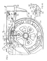
- Fig. 1 eine schematische Darstellung einer Antriebsvorrichtung für eine Dreschtrommel eines Mähdreschers, wobei Teile der Antriebsvorrichtung der besseren Darstellung wegen fortgelassen sind;
- Fig. 2 einen Längsschnitt durch eine Zugmittelscheibe entlang der Linie 2-2 gemäss Fig. 1 zum Antrieb der Dreschtrommel;
- Fig. 3 eine ähnliche Ansicht wie in Fig. 2 jedoch in kleinerem Massstab, wobei ein Gestänge mit einem Drehmomentenarm verbunden ist;
- Fig. 4 einen Teilquerschnitt entlang der Linie 4-4 gemäss Fig. 1, der die Verbindung des Gestänges mit dem Drehmomentenarm veranschaulicht;
- Fig. 5 eine ähnliche Ansicht wie in Fig. 3, wobei ein Verbindungsbolzen den Drehmomentenarm direkt mit der Zugmittelscheibe zum Antrieb der Dreschtrommel verbindet;
- Fig. 6 eine schematische Darstellung eines weiteren Ausführungsbeispiels einer Antriebsvorrichtung für die Dreschtrommel eines Mähdreschers;
- Fig. 7 einen Teilquerschnitt entlang der Linie 6-6 gemäss Fig. 9, wobei das Gestänge über einen Abscherbolzen an eine Halterung lösbar angeschlossen ist;
- Fig. 8 die Zugmittelscheibe mit einem Planetenträger und einer zweiten, über den Abscherbolzen festgelegten Zugmittelscheibe;
- Fig. 9 eine ähnliche Ansicht wie in Fig. 6, wobei Teile der Antriebsvorrichtung weggelassen worden sind, jedoch im grösseren Massstab;
- Fig. 10 eine Abscherverbindung zwischen einem Drehmomentenrad und dem zugehörigen Lenker;
- Fig. 11 einen Querschnitt der Zugmittelscheibe entlang der Linie 4-4 gemäss Fig. 9 für untersetzten Antrieb der Dreschtrommel;
- Fig. 12 eine ähnliche Ansicht wie in Fig. 11, wobei die Dreschtrommel direkt angetrieben wird.
- In der Zeichnung ist mit 10 ein Antriebssystem für eine Dreschtrommel 11 bezeichnet (siehe gestrichelte Linien in Fig. 1), die im Bereich des vorderen Endes des Dreschgehäuses 12 mit der zugehörigen Antriebsvorrichtung 10 aufgenommen ist. In Fig. 1 sind lediglich die Seitenwände 13 und 15 des Dreschgehäuses dargestellt. Die Dreschtrommel 11 befindet sich über einem Dreschkorb 14 und lagert zwischen den gegenüberliegenden Seitenwänden 13 und 15.
- Die Antriebsvorrichtung 10 weist eine über eine in der Zeichnung nicht dargestellte Verbrennungskraftmaschine antreibbare Antriebswelle 16 auf, die über ein Zugmittelgetriebe 17 eine Antriebsvorrichtung 18 antreibt. Weitere über die Antriebswelle 16 antreibbare Zugmittelgetriebe sowie die zugehörigen Bauteile sind der Einfachheit halber nicht dargestellt. Das Zugmittelgetriebe weist eine Zugmittelscheibe 20 auf, deren wirksamer Durchmesser durch eine in der Zeichnung nicht dargestellte Verstellvorrichtung veränderbar ist. Die Zugmittelscheibe 20 des Zugmittelgetriebes 17 ist über ein Zugmittel 22 mit einer auf einem Tragarm 26 drehbar gelagerten Zugmittelscheibe 24 antriebsverbunden. Im Arbeitseinsatz ist der Achsabstand zwischen der Zugmittelscheibe 20 und der Zugmittelscheibe 24 normalerweise konstant. Die Riemenlängung kann über eine Stellvorrichtung ausgeglichen werden. Hierzu gehört ein eine Mutter aufweisendes Gestänge 28, das mit seinem oberen Ende an den Tragarm 26 angeschlossen und mit seinem unteren Ende in einer an einer Halterung angeordneten Hülse aufgenommen ist, so dass durch Drehen einer Mutter der Achsabstand zwischen den Zugmittelscheiben 20, 24 verändert werden kann, ohne die Antriebsgeschwindigkeit zu verändern.
- Ein stufenlos einstellbares Zugmittelgetriebe 30 für den Endantrieb der Dreschtrommel 11 weist eine Zugmittelscheibe 32 auf, die auf der gleichen Welle wie die Zugmittelscheibe 24 angeordnet ist und über diese angetrieben wird. Über das Zugmittelgetriebe 30 wird eine Endantriebsvorrichtung 34 der Dreschtrommel 11 angetrieben. Die Zugmittelscheibe 32 steht hierzu über ein Zugmittel 42 mit der Endantriebsvorrichtung 34 in Antriebsverbindung, die auf einer Welle 36 angeordnet ist, und der einGestänge 38 zugeordnet ist (Fig. 4), das mit seinem vorderen Ende an einer Halterung 40 des Dreschgehäuses 12 schwenkbar gelagert ist. Die Zugmittelspannung des Zugmittels 42 wird über eine Spannrolle 44 aufrecht erhalten, die an einem schwenkbaren Hebel angeordnet ist, der über eine Spannvorrichtung 46 verstellbar ist. Die Welle 36 lagert in Wälzlagern 48, die in den Seitenwänden 13 und 15 des Dreschgehäuses 12 aufgenommen sind (in Fig. 2 ist lediglich die rechte Seitenwand 13 dargestellt).
- Das Drehmoment der Endantriebsvorrichtung 34 wird über eine Nabe 50, die seitlich vom Wälzlager 48 vorgesehen ist, auf die Welle 36 geleitet. Die Nabe 50 ist hierzu über eine Keilverzahnung mit der Welle 36 drehfest verbunden. Das innenliegende Ende der Nabe 50 weist einen sich radial erstreckenden Flansch 52 auf, während das aussenliegende Ende der Nabe 50 an seinem Aussenumfang eine Verzahnung 54 aufweist, die vor einem Wälzlagerring 56 eines Wälzlagers 58 endet, das auf der Nabe 50 angeordnet ist. Eine Zugmittelscheibe 60 ist am Flansch 52 der Nabe 50 mittels Schraubenbolzen konzentrisch angeschlossen und dient zum Antrieb einer Strohleittrommel 61, die in Fig. 1 und 6 in gestrichelten Linien angedeutet ist und stromabwärts vor der Dreschtrommel 11 liegt und eine Zugmittelscheibe 62 aufweist, die über ein Zugmittel 64 mit der Zugmittelscheibe 60 antriebsverbunden ist. Auf der Nabe 50 ist mittels des Wälzlagers 58 ein innenliegendes Scheibenteil 66 einer Zugmittelscheibe 68 der Endantriebsvorrichtung 34 gelagert. Der Scheibenteil 66 besteht aus einem sich radial erstreckenden Flansch mit daran änschliessender, geneigt verlaufender Wand 70, die mit einem radial verlaufenden Steg 72 verbunden ist, an dem ein Zugmittelrillen 76 aufweisender Scheibenkranz 74 angeschlossen ist. Das Zugmittel 42 bzw. der Treibriemen wird von den Zugmittelrillen 76 aufgenommen. Drei einen gleichen Abstand untereinander aufweisende Augen bzw. Angüsse 78 (Fig. 1, 9) sind an dem Steg 72 angeordnet und erstrecken sich von diesem nach aussen, wobei jeder Anguss 78 mit einer Bohrung 80 versehen ist. Die Zugmittelscheibe 68 bzw. der Scheibenteil 66 weist ferner eine konzentrisch zur Welle 36 angeordnete Ringwand 82, auf, die sich von der inneren Kante des Steges 72 nach aussen erstreckt und mit einer radial verlaufenden Stirnfläche 84 versehen ist, die rechtwinklig zur Drehachse der Zugmittelscheibe 68 verläuft und mit der Wand 70 ein Gehäuse 85 zur Aufnahme eines Getriebes beispielsweise eines Planetengetriebes 90 bildet. Zur Endantriebsvorrichtung 34 gehört ferner eine mit einer Innenverzahnung versehene Buchse 86, deren Verzahnung mit der Verzahnung 54 der Nabe 50 in Eingriff steht und die mittels eines Federringes 88 auf der Nabe 50 gesichert ist.
- Die drehbaren Teile der Endantriebsvorrichtung 34 werden durch das Planetengetriebe 90 vervollständigt, das mittels eines Planetenträgers 110 und Schraubenbolzen 92 am Scheibenteil 66 angeordnet ist. Das Planetengetriebe 90 besteht aus einem Ausgangssonnenrad 94, das konzentrisch zur Welle 36 angeordnet ist und mit seiner Keilverzahnung 96 auf der ebenfalls eine Keilverzahnungen aufweisende Buchse 86 aufgezogen und mittels des Federringes 88 axial gesichert ist. Ein zweites bzw. ein Eingangssonnenrad 98 ist über ein nach aussen und ein nach innen geneigt verlaufendes Schrägrollenlager 100 und 102 auf der Welle 36 drehbar gelagert. Eine Distanzhülse 104 sichert die Schrägrollenlager 100 und 102 gegen axiale Verstellung. Das Sonnenrad 98 ist mit einer länglichen sich nach aussen erstreckenden Nabe versehen, das einen Sitz 106 aufweist und die im Bereich ihres aussenliegenden Endes eine Keilverzahnung 108 aufweist. Ein zweites Wälzlager 58 ist auf dem Sitz 106 der Nabe des Sonnenrades 98 angeordnet.
- Der Planetenträger 110 weist einen Flansch 112 auf, der mittels des zweiten Wälzlagers 58 auf der Welle 36 drehbar gelagert ist. Der Flansch 112 ist mit einer eine Sackbohrung aufweisenden Nabe 114 versehen, in der das zweite Wälzlager 58 aufgenommen ist. Der Flansch 112 ist mit einer nach innen gerichteten Stirnfläche 116 versehen, die gegen die Stirnflächen 84 der Ringwand 82 der Zugmittelscheibe 68 anliegt. An den Flansch 112 ist ein Steg 118 angeschlossen, der sich von dem Flansch 112 in das Innere des Gehäuses 85 des Planetengetriebes 90 erstreckt und drei mit Abstand zueinander angeordnete Planetengetriebeteile 120 trägt, wobei in Fig. 2 und 8 lediglich ein Planetengetriebeteil dargestellt ist. Jedes Planetengetriebeteil 120 besteht aus einem ersten Planetenrad 122 an dem ein zweites Planetenrad 124 fest bzw. einteilig angeschlossen ist und das mit dem ersten bzw. Ausgangssonnenrad 94 und dem zweiten bzw. Eingangssonnenrad 98 zusammenwirkt. Die Planetenräder 122 und 124 sind auf je einer am Flansch 112 des Planetenträgers 110 angeordneten Achse 125 gelagert. Ein Ringflansch 126, der an die Stege 118 mittels Schraubenbolzen lösbar angeschlossen ist, dient zur zusätzlichen Lagerung der freien Enden der Achsen 125.
- Ausserhalb des Getriebegehäuses 85 im Bereich der Nabe 114 ist auf der Nabe 50 des Eingangssonnenrades 98 eine Drehmomentenvorrichtung 127 mittels einer Keilverzahnung 108 befestigt. Die Drehmomenteneinrichtung 127 weist ein Drehmomentenkreuz 128 (Fig. 2) auf, das mit einer Nabe 130 versehen ist. Das Drehmomentenkreuz 128 besteht aus zwei diametral gegenüberliegenden Stellarmen, wobei der eine Stellarm 132 für den direkten Antrieb und der zweite Stellarm 134 zur Drehzahluntersetzung vorgesehen ist. Die äusseren Enden der Arme 132 und 134 sind einander gleich und dienen der unterschiedlichen Antriebsverbindung. Der Arm 132 weist ein Lagerauge 136 mit einer Bohrung 138 auf, deren Achse parallel zur Achse der Welle 36 verläuft und die mit einer der drei Bohrungen 80 des Scheibenteiles 66 in Übereinstimmung gebracht werden kann (Fig. 2). Im Bereich der Bohrung 138 an der aussenliegenden Seite des Lagerauges 136 befinden sich zwei gegenüberliegende Anschläge 140 (Fig. 1 und 2). Der Stellarm 134 zur Reduzierung der Geschwindigkeit weist im Bereich seines äusseren Endes ein dem Lagerauge 136 ähnliches Lagerauge 142 auf, das ebenfalls mit einer Bohrung 144 versehen ist, die parallel zur Achse der Welle 36 verläuft und mit Bezug auf die Welle 36 auf einem Radius liegt, der etwas grösser ist als der Radius, auf dem die gegenüberliegende Bohrung 138 verläuft. Das Lagerauge 142 ist mit Bezug auf die Mittellinie des Drehmomentenarmes 128 versetzt angeordnet und weist eine Schulter 146 auf, die rechtwinklig zur Achse des Armes 134 verläuft.
- Ein kurzer Lenker 148 erstreckt sich von dem Drehmomentenkreuz 128 radial nach aussen und ist am Lagerauge 142 mittels eines Schraubenbolzens 150 gesichert, der durch eine im Lenker 148 vorgesehene Bohrung 152 und durch die im Lagerauge 142 vorgesehene Bohrung 144 gesteckt und mittels einer Mutter gesichert ist. Zur Bohrung 144 ist mit Abstand nach innen eine zweite Bohrung 154 im Lenker 148 vorgesehen, wobei die Bohrungen 152 und 154 auf einer Ebene verlaufen, die rechtwinklig zur Achse des Drehmomentenkreuzes 128 angeordnet sind. Die Drehmomentenvorrichtung 127 ist auf der Nabe des zweiten Sonnenrades 98 mittels einer Keilverzahnung 108 und einer Mutter 156 gesichert, während das gesamte Planetengetriebe 90 auf der Welle 36 mittels einer schmäleren Mutter 158 gesichert ist, die von einer Kappe 160 abgedeckt ist. Die Kappe 160 und eine Ringdichtung 161 dichten den Raum, in dem die Schrägrollenlager 100 und 102 vorgesehen sind, nach aussen hin ab.
- Das Gestänge 38 (Fig. 1 und 4) ist in einer vertikal verlaufenden Ebene verschwenkbar, die rechtwinklig zur Achse der Welle 36 verläuft und gelenkig auf der Halterung 40 angeschlossen. Das Gestänge 38 weist hierzu eine Gabel 162 auf, die auf einem mit der Halterung 40 verbundenen Bolzen 164 schwenkbar gelagert ist. Das der Gabel 162 gegenüberliegende Ende weist eine Doppelgabel 166 auf, in der eine Bohrung 168 vorgesehen ist, deren Achse parallel zur Achse des Bolzens 164 verläuft. Die Doppelgabel 166 bildet einen inneren und äusseren Schlitz 170, 172. Ein Anschlag 174 erstreckt sich von dem Schlitz 170 nach innen unmittelbar unterhalb der Bohrung 168. Eine Zugfeder 176 ist einenends an eine Öse 178 des Gestänges 38 und an eine Anschlaghalterung 180 angeschlossen, die mit dem Dreschgehäuse 12 starr verbunden ist.
- Bei der vorliegenden Erfindung wird die Drehzahl der Dreschtrommel 11 über das stufenlos einstellbare Zugmittelgetriebe 17 eingestellt, wobei zwei Drehzahlbereiche erfindungsgemäss möglich sind. Der erste Drehzahlbereich ergibt sich bei direktem Antrieb und bei Ankupplung des mit den Zugrillen 76 versehenen Teiles der Zugmittelscheibe 68 an die Welle 36 (Fig. 2). Der zweite Drehzahlbereich wird bei indirektem Antrieb über das Planetenradgetriebe 90 ermöglicht (Fig. 2 und 8).
- Wird ein direkter Antrieb für die Dreschtrommel 11 gewünscht, so wird die Bohrung 138 des Drehmomentenkreuzes 128 (Fig. 2) so verstellt, dass er mit einer der Bohrungen 80 der Zugmittelscheibe 68 fluchtet, so dass ein Bolzen 182 in die Bohrung 80 und 138 eingeführt werden kann, um das Drehmomentenkreuz 128 mit der Zugmittelscheibe 68 drehfest zu verbinden (Fig. 5). Am äusseren Ende 184 (Fig. 4, 5) des Bolzens 182 ist eine Querbohrung zur Aufnahme einer Federsicherung 186 vorgesehen, während im Bereich des Schlitzes 170 der Bolzen 182 eine weitere Bohrung zur Aufnahme eines Federsplints 188 aufweist. Die beiden Bohrungen im Bolzen 182 verlaufen parallel zueinander, so dass bei einer etwaigen Drehung des Bolzens 182 die Federsicherung 186 gegen den Anschlag 140 zur Anlage kommt, so dass der Federsplint 188 seine im Schlitz vorgesehene Lage beibehält und der Bolzen 182 beim Arbeitseinsatz und der auftretenden Zentrifugalkräfte nicht aus der Bohrung herausgleitet. Bei direkter Antriebsverbindung bleibt das Gestänge 38 in seiner nach oben geschwenkten Lage, in der es sich gegen die Anschlaghalterung 180 anlegt und die Drehmomentenvorrichtung 127 freigibt, wobei die Zugfeder 176 das Gestänge 38 nach oben zieht (siehe Fig. 5). ist das Drehmomentenkreuz 128 über den Bolzen 182 (Fig. 5) mit dem Scheibenteil 66 drehfest verbunden, so kann sich das zweite Sonnenrad 98 mit Bezug auf den Scheibenteil 66 nicht drehen, so dass der Antrieb unter Ausschaltung des Planetengetriebes 90 direkt auf die Welle 36 geleitet wird.
- Bei reduzierter Ausgangsdrehzahl (Fig. 1, 3 und 4) wird der auf dem Stellarm 134 angeordnete Lenker 148 und die Gabel 166 des Gestänges 38 zusammengeführt und das eine Ende des Lenkers 148 in den Schlitz 170 geschoben, bis die Bohrungen 154 und 168 des Lenkers 148 und des Gestänges 38 untereinander fluchten. Um die beiden Teile miteinander zu kuppeln wird der Bolzen 182 in die Bohrungen 154 und 168 eingeführt und durch Einsetzen des Federsplints 188 in die Bohrung des Bolzens 182 zwischen dem Schlitz 172 gesichert. Da die beiden Bohrungen des Bolzens 182 auf der gleichen, sich durch den Bolzen 182 erstreckenden Querebene liegen, ist es leichter, den Federsplint 188 einzuführen, da die Lage der Federsicherung 186 in der Bohrung am äusseren Ende 184 des Bolzens 182 der Bedienungsperson anzeigt, wo der Federsplint 188 in die benachbarte Bohrung des Bolzens 182 eingeführt werden kann. Bei reduzierter Drehzahl der Dreschtrommel 11 sichert das Gestänge 38 das Drehmomentenkreuz 128, so dass es mit Bezug auf das Dreschgehäuse 12 keine Drehbewegung mehr ausführen kann. Hierdurch wird das zweite Sonnenrad 98 ebenfalls festgehalten und der Kraftfluss von der Zugmittelrille 76 läuft über das Reduktionsgetriebe, d.h. über das zweite Sonnenrad 98 bzw. das Eingangssonnenrad 98, das zweite Planetenrad 124, das erste Planetenrad 122 auf das Ausgangssonnenrad 94 auf die Welle 36. Das Drehmomentenkreuz 128 bildet ein wirksames Übertragungselement, zumal die Lageraugen 136 und 142 direkt neben der Stirnfläche des Scheibenkranzes 74 mit den Zugmittelrillen 76 liegen, so dass die Tangentialkräfte relativ klein gehalten werden können, da der Radialabstand zur Welle 36 klein ist, so dass dadurch relativ kleine Bauteile zur Drehmomentenübertragung verwendet werden können.
- Bei reduziertem Antrieb der Dreschtrommel 11 ist das Drehmoment, das auf die treibenden Teile übertagen wird (Welle 36, Dreschtrommet 11), bei einer bestimmten Eingangsleistung grösser, wobei jedoch die Zugmittel 22 und 42 so ausgebildet sind, dass sie das überhöhte Drehmoment übertragen können, so dass eine Überlast an der Welle 36 bzw. an der Dreschtrommel 11 auftreten kann. Die Scherverbindung mittels des Schraubenbolzens 150 zum Anschluss des Lenkers 148 an das Lagerauge 142 des Drehmomentenkreuzes 128 ist so ausgelegt, dass bei einer bestimmten Grösse des Drehmomentes der Abscherbolzen, der durch den Schraubenbolzen 150 dargestellt wird, abscheren kann, so dass keine Beschädigung am Getriebe bzw. an den Arbeitsorganen auftreten kann. Beim Abscheren des Abscherbolzens 150 kann das Drehmomentenkreuz 128 frei drehen, wobei beim Abschervorgang das Gestänge 38 mittels der Feder 76 sofort nach oben gezogen wird, so dass das Drehmomentenkreuz 128 ungestört drehen kann, ohne dass es mit dem Gestänge 38 kollidiert.
- Eine Abscherung des Abscherbolzens 150 tritt beispielsweise dann auf, wenn die Dreschtrommel 11 übermässig stark mit Erntegut beschickt wird. Tritt also eine Überlast auf, so kann eine Korrektur der Überlast nach Abscheren des Abscherbolzens 150 vorgenommen werden und dann ein neuer Abscherbolzen wieder eingesetzt werden, so dass die Arbeit des Mähdreschers fortgesetzt werden kann. Hierzu ist es der Einfachheit halber möglich, zusätzliche Schraubenbolzen 150 in einer Halterung 190 (Fig. 1) vorzusehen, die am Dreschgehäuse 12 im Bereich des oberen Endes des Drehmomentenkreuzes 128 angeordnet ist.
- Um also einen direkten oder indirekten Antrieb für die Dreschtrommel 11 zu ermöglichen, kann auf einfache Weise die gewünschte Verbindung zwischen dem Drehmomentenkreuz 128 und der Zugmittelscheibe 68 bzw. zwischen dem Drehmomentenkreuz und dem Gestänge 38 hergestellt werden. Ferner sind das Gestänge 38 sowie das Drehmomentenkreuz 128 so augebildet, dass eine Fehlkupplung durch falsches Zusammenschliessen der einzelnen Teile ausgeschaltet ist. Beispielsweise wird der Versuch, das Gestänge 38 an die getriebene Zugmittelscheibe 68 anzuschliessen,durch den Anschlag 174 verhindert, der sich gegen die Schulter des Flanches 112 anlegt. Hierdurch wird verhindert, dass die Bohrung 168 zur Bohrung 80 des Lagerauges 78 ausgerichtet wird (Fig. 3). Ferner liegt die Bohrung 80 der Zugmittelscheibe 68 auf einem kleineren Durchmesser als die Bohrung 154 des Lenkers 148. Somit ist es nicht möglich, das Gestänges 38 und den Lenker 148 mit der Zugmittelscheibe 68 zu verbinden, da ein versehentliches Einführen des Bolzens 182 in die Bohrung 168 des Gestänges 38, ein Einführen in die Bohrung 80 des Zugmittelscheibe 68 nach Ausrichten der Zugmittelscheibe 68 nicht gestattet.
- Die kompakte Bauweise der Dreschtrommel 11 und der zugehörigen Antriebskomponenten geht insbesondere aus der Darstellung gemäss Fig. 2 hervor. Die Zugmittelscheibe 60 und die Zugmittelscheibe 68 mit den Zugmittelrillen 76 sind dicht an der Aussenseite der Wand 13 des Dreschgehäuses 12 vorgesehen und die Getriebeteile des Planetenradgetriebes 90 liegen innerhalb der Gesamtbreite der Zugmittelscheibe 68 und sind in dieser integriert. Das Drehmomentkreuz 128 verbreitert nur geringfügig die Gesamtbreite des Mähdreschers bzw. der Antriebsvorrichtung ausserhalb der Wand 13 des Mähdreschers. Die einfache Handhabung mit der Möglichkeit des Wechsels zwischen direktem und indirektem Antrieb für die Dreschtrommel 11 ergibt sich ohne weiteres aus den Zeichnungen. Ferner kann nur ein unterschiedlich kuppelbarer Bolzen 182 für beide Antriebsarten verwendet werden. Die Möglichkeit der Unterbringung von Ersatzabscherbolzen 150, die den Verlust solcher Ersatzabscherbolzen ausschaltet, stellt eine vorteilhafte Massnahme dar. Der Bolzen 182 kann ohne Arbeitswerkzeuge relativ leicht in die Bohrungen der Zugmittelscheibe 68, des Gestänges 38 und des Lenkers 148 eingesetzt werden, so dass ein schneller Wechsel von der einen Antriebsart auf die andere Antriebsart möglich ist. Da drei mit Abstand zueinander angeordnete Bohrungen 80 in der Zugmittelscheibe 68 vorgesehen sind, wird die Umstellung für die direkte Antriebsart noch weiterhin vereinfacht. Ein Verschleiss der in Eingriff stehenden gegeneinander nicht drehenden Zahnräder ist bei dieser Antriebsart gering, wenn zur Sperrung des Planetengetriebes 90 drei verschiedene Anschlussbohrungen 80 an der Zugmittelscheibe 68 zur Verfügung stehen. Der Ein- und Ausbau sowie der Service an der Endantriebsvorrichtung 34 ist leicht und schnell. durchzuführen. Durch Entfernen der Kappe 160 und der Mutter 158 und der Schraubenbolzen 92, kann des gesamte Planetengetriebe 90 von der Welle 36 abgezogen werden und damit ein leichter Zugang ins Innere des Gehäuse 85 und zu den einzelnen Getriebeteilen ermöglicht werden, ohne dass der relativ schwere aussenliegende Scheibenteil 66 von der Welle 36 abgenommen zu werden braucht. Jedoch wirkt bei grösseren Wartungsarbeiten der Abbau der gesamten Endantriebsvorrichtung 34 als Baueinheit.
- Die in Fig. 8 dargestellten Zugmittelscheiben 60 und 68 unterscheiden sich nur geringfügig von den Zugmittelscheiben 60 und 68 gemäss Fig. 2. Die Zugmittelscheibe 60 kann gemäss Fig. 8 über einen Bolzen 308 mit der angrenzenden Zugmittelscheibe 68 antriebsverbunden werden. Die Schraubenbolzen 92 (Fig. 8) zur Sicherung des Flansches 112 am Scheibenteil 66 weisen zusätzliche Schraubenbolzensicherungselemente 193 (Fig. 9) mit je einer Aussparung 195 auf, die mit der Bohrung 80 zur Aufnahme des Schraubenbolzens 308 fluchtet.
- Anstelle des in Fig. 2 dargestellten Drehmomentenkreuzes 128 ist in den Fig. 8, 9 ein Drehmomentenrad 232 vorgesehen, dass ein Nabenteil 234 aufweist, das über Arme 236 mit einem Ringrad 238 (Fig. 9) verbunden ist. Das Ringrad 238 weist eine relativ flache Aussparung 240 und diametral gegenüber einen Scherbolzenanschlussteil 242 (Fig. 10) auf. Am Scherbolzenanschlussteil 242 ist, wie aus Fig. 8 und 10 zu entnehmen ist, eine sich radial erstreckende Rippe 244 vorgesehen, die konzentrisch zum Drehmomentenrad 232 verläuft. Im Scherbolzenanschlussteil 242 ist eine sich radial erstreckende Bohrung 246 vorgesehen, die mittig durch die Rippe 244 verläuft.
- Im normalen Arbeitseinsatz ist eine Anschlussöse 250 an die Rippe 244 des Scherbolzenanschlussteiles 242 mittels eines Schraubenbolzens 252 angeschlossen, der sich durch eine Bohrung 254 in der Anschlussöse 250 und durch eine Bohrung 246 des Drehmomentenrades 232 erstreckt. Die Anschlussöse 250 weist eine kreisbogenförmige Oberfläche 246 auf, die gegen die Rippe 244 anliegt (Fig. 10). In der Anschlussöse 256 ist ferner eine Bohrung 258 vorgesehen, die rechtwinklig zur Rippe 244 verläuft. An der Anschlussöse 250 ist ferner mit Abstand zur Bohrung 258 eine Tragkante 260 (Fig. 10) vorgesehen.
- Das Drehmomentenrad 232 ist über eine Keilverzahnung 108 und mittels einer Mutter 262 auf der Nabe des Sonnenrades 98 des Planetengetriebes 90 befestigt. Das gesamte Planetengetriebe 90 ist auf die Welle 36 mittels einer kleineren Mutter 264 gesichert die mittels einer Kappe 266 abgedeckt ist. Die Kappe 266 bildet mit einer Dichtung 268 seitlich des Schrägrollenlagers 100 eine Schmiermittelkammer für das zweite Sonnenrad 98.
- Das Gestänge 38' besteht aus einem T-Profil (Fig. 7 und 9), an dem endseitig je eine Gabel 274, 280 vorgesehen ist. Das Gestänge 38' ist in einer vertikal verlaufenden Ebene verschwenkbar, die rechtwinklig zur Welle 36 verläuft. Das Gestänge 38' ist über die Gabel 274 und einen Bolzen 276 an die Halterung 40 schwenkbar angeschlossen. An dem der Gabel 274 gegenüberliegenden Ende des Gestänges 38' ist die Gabel 280 mit einer Bohrung 282 vorgesehen, die parallel zur durch den Bolzen 276 verlaufenden Schwenkachse verläuft. Der die beiden Gabelteile miteinander verbindende Steg, der Gabel 280 weist eine geneigt verlaufende, bearbeitete Oberfläche 284 auf.
- Seitlich des Gestänges 38' erstreckt sich eine über das Ende der Gabel 280 reichende Befestigungsvorrichtung 286 die als Hebel ausgebildet ist und die, mittels Schraubenbolzen an eine am Gestänge 38' vorgesehene Lasche 288 angeschlossen ist. Die Befestigungsvorrichtung 286 weist ein Arretierungsteil 290 auf, dessen freies Ende nach unten hakenförmig abgehoben ist (siehe Fig. 9). An die Lasche 288 ist ferner ein hakenförmiges Befestigungselement 292 angeschlossen, das an seinem freien Ende einen halbkreisförmigen Hakenteil 294 aufweist (Fig. 11), der koaxial zur Bohrung 282 des Gestänges 38' verläuft. Das Hakenteil 294 weist zwei innenliegende Rillen 296 und eine aussenliegende Rille 298 auf. Eine Zugfeder 300 ist einenends an eine am Gestänge 38' vorgesehene Öse 302 und anderenends an eine an der Halterung 40 vorgesehen Lasche 304 angeschlossen.
- Die in Fig. 11 dargestellte Zugmittelscheibe 68 ist auf untersetzten Antrieb und die in Fig. 12 dargestellte gleiche Zugmittelscheibe 68 auf direkten Antrieb eingestellt. Der direkte Antrieb zum Antrieb der Welle 36 wird dadurch ermöglicht, dass das Drehmomentenrad 232 mit einer Bohrung 80 im Lagerauge 78 soweit gedreht wird, bis die Bohrung 80 mit einer Bohrung 67 der Zugmittelscheibe 65 zum Antrieb einer Schlagtrommel fluchtet. Die untereinander fluchtenden Bohrungen 67 und 80 (Fig. 11,12) liegen auf dem gleichen Radius wie die Aussparung 240 des Ringrades 238 (Fig. 9). Der Scheibenteil 66 wird dann an die Zugmittelscheibe 65 mittels einer Steckverbindung 306 angekuppelt. Die Steckverbindung 306 weist einen Bolzen 308 mit einer Splintfeder 310 auf, die in eine entsprechende Querbohrung im Bolzen 308 eingeführt ist. Die Steckverbindung ist mittels einer Klammersicherung 312 gesichert. Die in dem Bolzen 308 vorgesehenen Querbohrungen sind so aufeinander abgestimmt, dass eine Drehung des Bolzens 308 durch Anlage der Splintfeder 310 gegen eine Schulter 314 (Fig. 8) des Schraubenbolzensicherungselementes 193 begrenzt wird. Somit hält die Klammersicherung 312 ihre Lage und verhindert dadurch ein Herausgleiten des Bolzens 308 aus der Bohrung 80 in Folge zentrifugaler Kräfte, die beim Arbeitseinsatz auftreten können.
- Bei direktem Antrieb wird das Gestänge 38' mit dem Arretierungsteil 290 in eine obere Stellung (siehe Fig. 9, gestrichelter Arretierungsteil 290') verstellt, wobei die Feder 300 den Arretierungsteil gegen einen Anschlag 316 zieht, der am Dreschgehäuse 12 angeordnet ist, und dadurch das Drehmomentenrad 232 freigibt. Gemäss Fig. 12 ist die Zugmittelscheibe 60 mit der Zugmittelscheibe 65 fest verbunden, die auf der Welle 36 (Fig. 8) drehfest angeordnet ist, so dass der direkte Antrieb von den Zugmittelrillen 76 der Zugmittelscheibe 68 auf die Welle 36 geleitet wird, wobei der Kraftfluss nicht über das in der Zugmittelscheibe 68 vorgesehene Planetengetriebe 90 läuft. Das Gleichgewicht bzw. ein Auswuchten des Planetengetriebes 90 bei direktem Antrieb wird durch die entsprechende Dimensionierung der Aussparung 240 und die vorteilhafte Lage der gegenüberliegenden Steckbolzenverbindung 306 erreicht. Die Steckbolzenverbindung 306 kann mit Bezug auf die Aussparung 240 nur um 180° versetzt am Drehmomentenrad 232 vorgesehen werden. Bei direktem Antrieb wird die Steckbolzenverbindung im Bereich der Aussparung 240 montiert so dass eine gute Auswuchtung für die drehenden Teile bei direktem Antrieb gewährleistet ist (Fig. 12).
- Bei untersetztem Antrieb (Fig. 7, 9 und 11) wird die Gabel 280 des Lenkers 38' an die am Drehmomentenrad 232 vorgesehen Anschlussöse 250 herangeschwenkt, wobei die Anschlussöse 250 in die Gabel 280 hineingeführt wird, so dass die Bohrungen 258 und 282 der Anschlussöse 250 und der Gabel 280 untereinander fluchten. Um die Anschlussöse 250 und die Gabel 280 fest miteinander zu verbinden, braucht lediglich der Bolzen 308 in die Bohrungen eingeführt zu werden, um dann mittels der Klammersicherung 312 festgesetzt zu werden, die in die Rille 296 des Befestigungselementes 292 und in die Querbohrung des Bolzens 308 eingesetzt wird.
- Da bei direktem und indirektem Antrieb die beiden Bohrungen in dem Bolzen 308 auf der gleichen Querebene liegen, ist es leichter, die Klammersicherung 312 einzusetzten, da die Stellung der Splintfeder 310 im Bolzen 308 anzeigt, wo die Klammersicherung 312 eingesetzt werden muss. Ferner ist die Splintfeder 310 durch Anlage an die Schulter 314 an dem Schraubenbolzensicherungselement 193 fixiert (Fig. 8 direkter Antrieb). Die Rille 298 des Hakenteiles 294 des Befestigungselementes 292 (Fig. 11 untersetzter Antrieb) dient als Führung zur Ausrichtung der Bohrung, in der die Klammersicherung 312 eingeführt werden muss.
- Bei direktem Antrieb sichert das Gestänge 38' das Drehmomentenrad 232 drehfest am Dreschgehäuse 12, so dass das zweite Sonnenrad 98 ebenfalls festgehalten wird und der Kraftfluss von den Zugmittelrillen 76 über das Planetengetriebe 90, d.h. über das zweite Eingangssonnenrad 98, das Planetenrad 124, das Planetenrad 122 auf das Ausgangssonnenrad 94 und somit auf die Welle 36 geleitet wird.
- Das Drehmomentenrad 232 bildet ein wirksames Übertragungselement, wobei an der Eingangsstelle (Anschlussstelle, Anschlussöse 250, dicht neben der Aussenoberfläche der Zugmittelrillen 76) die tangentialen Kräfte relativ klein sind, da auch der radiale Abstand zur Achse der Welle klein ist. Durch diese Anordnung kann mit relativ leicht dimensionierten Bauteilen ausgekommen werden.
- Bei untersetztem Antrieb steigt das Drehmoment, das auf die drehbaren Teile übertragen wird (Welle 36 und Dreschtrommet 11) bei einer bestimmten Eingangsleistung natürlich an. Die Zugmittel 22, 24sind jedoch so ausgelegt, dass das bei Überlast auftretende Drehmoment übertragen werden kann. Die Scherverbindung bzw. das Kupplungselement (Abscherbolzen 252 zum Anschluss der Anschlussöse 250 am Drehmomentenrad 232) ist so dimensioniert, dass bei einem bestimmten Drehmoment ein Abscheren erfolgt, so dass die Welle 36 sowie die Dreschtrommel 11 bzw. andere Komponenten nicht beschädigt werden. Nach dem Abschervorgang kann das Drehmomentenrad 232 frei drehen, wobei das Gestänge 38' sofort über die Zugfeder 300 gegen den Anschlag 316 (Fig. 9) gezogen wird, so dass das Drehmomentenrad 232 nicht mit diesen Teilen in Berührung kommt. Die Anschlussöse 250 bleibt nach diesem Abschervorgang an dem Gestänge 38' angeschlossen, wobei durch Anlage derTragkante 260 an der Oberfläche 284 die Anschlussöse 250 nicht nach unten schwenkt, so dass die Anschlussöse 250 keinen Kontakt mehr mit dem Ringrad 238 bekommt. Durch die kreisförmige Oberfläche des Ringrades 238 und die konzentrische Ausbildung der Rippe 244 mit einem Radius der etwas grösser ist als der Radius des Ringrades 234 in Verbindung mit glatten Kontaktflächen zwischen den beiden Teilen wird somit eine hindernisfreie Aussenkontur an den beiden Teilen geschaffen, so dass bei einem unbeabsichtigten Kontakt zwischen dem Lenker 38' und dem Drehmomentenrad 232 keine Beschädigungen auftreten.
- Ein Abscheren des Abscherbolzens 252 kann infolge einer Überlast durch übermässige Erntegutzufuhr zur Dreschtrommel 11 auftreten. Tritt beispielsweise eine Überlast auf und schert dabei ein Schraubenbolzen ab, so lässt dieser sich ohne weiteres wieder ersetzen und die Arbeit kann mit dem Mähdrescher fortgesetzt werden. Hierzu können entsprechende Abscherbolzen an einer Halterung 318 vorgesehen werden (Fig. 9), die am Dreschgehäuse 12 in der Nähe der Scherverbindung vorgesehen ist.
- Die einzelnen Elemente sind so bemessen, dass ein Umrüsten von einer Betriebsart auf eine andere Betriebsart ohne weiteres möglich ist, ohne dass die Teile falsch miteinander gekuppelt werden. Somit ist ein unbeabsichtigtes Ankuppeln des Gestänges 38' an die getriebene Scheibe durch die Gabel 280 bei Anlage des Gestänges 38' auf dem Ringrad 238 des Drehmomentenrades 232 ausgeschlossen, da die Bohrung 282 der Gabel 280 nicht der Bohrung 80 des Scheibenteiles 66 fluchtend ausgerichtet werden kann (Fig. 11 und 12). Ferner liegt der Radius der Bohrung 80 des Scheibenteiles 66 auf einem kleineren Radius als die Bohrung 258 der Anschlussöse 250. Auf diese Weise wird ausgeschaltet, dass beim Anschluss des Gestänges 38' an die Anschlussöse 250 der Bolzen 308 nicht versehentlich so weit in die Bohrung 282 eingeführt werden kann, dass er auch in die Bohrung 80 des Scheibenteiles 60 eintritt.
- Die Zugmittelscheibe 60 mit den zugehörigen Zugmittelrillen 76 ist relativ dicht an der Seitenwand 13 des Mähdreschers angeordnet. Die einzelnen Getriebeteile des Planetengetriebes 90 sowie der Flansch der Zugmittelscheibe 65 liegen innerhalb der axialen Ausdehnung des Scheibenkranzes 74 des Zugmittelscheibe 68. Das Drehmomentenrad 232 nimmt relativ wenig Platz ausserhalb der Seitenwand 13 sowie seitlich der Zugmittelscheibe 68 ein. Die Steckverbindung 306 kann für beide Antriebsarten eingesetzt werden, so dass keine zusätzliche Unterbringung der Steckverbindung erforderlich ist und somit keine Teile ohne weiteres verloren werden können. Der Bolzen 308 kann ohne weiteres in die Bohrungen 67,80 der Zugmittelscheibe 68 und des Flansches der zusätzlichen Zugmittelscheibe 65, der Anschlussöse 250 und in die Bohrung des zugehörigen Lenkers 38' eingesetzt werden, wobei zum Umrüsten auf eine andere Antriebsart keine Arbeitswerkzeuge erforderlich sind. Durch die Verwendung von drei mit Abstand zueinander angeordneten Bohrungen 80 in der Zugmittelscheibe 68 ist das Umrüsten für direkten Antrieb relativ teicht möglich. Ferner kann bei direktem Antrieb das Planetengetriebe 90 geschont werden, da der Kraftfluss bei direktem Antrieb nicht über das Planetengetriebe läuft.
- Der Ein- und Ausbau sowie die Wartung der Endantriebsvorrichtung 34 ist relativ leicht durchzuführen. Durch die Entfernung der Schraubenbolzen 92 der Kappe 266 und der Mutter 264 kann das gesamte Planetengetriebe 90 ohne weiteres von der Welle 36 abgezogen werden, so dass relativ leicht an das Gehäuse 85 der Zugmittelscheibe 68 herangekommen werden kann. Der Ein- und Ausbau des Planetengetriebes 90 ist ohne Abbau der relativ schweren Zugmittelscheibe 68 möglich. Der gesamte Endantrieb 34 kann ausserdem als Baugruppe an und abgebaut werden, wenn dies aus Reparaturgründen notwendig ist.
Claims (25)
Applications Claiming Priority (4)
| Application Number | Priority Date | Filing Date | Title |
|---|---|---|---|
| US06/299,277 US4454787A (en) | 1981-09-04 | 1981-09-04 | Variable drive for a harvester functional element |
| US06/395,767 US4483128A (en) | 1982-07-06 | 1982-07-06 | Variable drive for a harvester functional element |
| US299277 | 1989-01-23 | ||
| US395767 | 1989-08-18 |
Publications (2)
| Publication Number | Publication Date |
|---|---|
| EP0074097A1 EP0074097A1 (de) | 1983-03-16 |
| EP0074097B1 true EP0074097B1 (de) | 1985-09-04 |
Family
ID=26971131
Family Applications (1)
| Application Number | Title | Priority Date | Filing Date |
|---|---|---|---|
| EP19820108145 Expired EP0074097B1 (de) | 1981-09-04 | 1982-09-03 | Antriebsvorrichtung für eine landwirtschaftlich nutzbare Maschine |
Country Status (4)
| Country | Link |
|---|---|
| EP (1) | EP0074097B1 (de) |
| DE (1) | DE3266039D1 (de) |
| ES (1) | ES515479A0 (de) |
| SU (1) | SU1245250A3 (de) |
Families Citing this family (3)
| Publication number | Priority date | Publication date | Assignee | Title |
|---|---|---|---|---|
| DE102017010230A1 (de) * | 2017-11-06 | 2019-05-09 | Maschinenfabrik Bernard Krone GmbH & Co. KG | Landwirtschaftliche Erntemaschine |
| CN109076792B (zh) * | 2018-09-11 | 2023-10-03 | 铜陵汇宇实业有限公司 | 主离合张紧轮支架 |
| US11452252B2 (en) * | 2020-01-16 | 2022-09-27 | Cnh Industrial America Llc | Torque damper for agricultural harvester header |
Family Cites Families (2)
| Publication number | Priority date | Publication date | Assignee | Title |
|---|---|---|---|---|
| DD100133A1 (de) * | 1972-11-27 | 1973-09-12 | ||
| US4138837A (en) * | 1976-10-26 | 1979-02-13 | Deere & Company | Variable speed reversible drive for a harvesting apparatus |
-
1982
- 1982-09-03 EP EP19820108145 patent/EP0074097B1/de not_active Expired
- 1982-09-03 DE DE8282108145T patent/DE3266039D1/de not_active Expired
- 1982-09-03 ES ES82515479A patent/ES515479A0/es active Granted
- 1982-09-03 SU SU823488351A patent/SU1245250A3/ru active
Also Published As
| Publication number | Publication date |
|---|---|
| EP0074097A1 (de) | 1983-03-16 |
| SU1245250A3 (ru) | 1986-07-15 |
| DE3266039D1 (en) | 1985-10-10 |
| ES8401301A1 (es) | 1983-12-16 |
| ES515479A0 (es) | 1983-12-16 |
Similar Documents
| Publication | Publication Date | Title |
|---|---|---|
| DE2745564C2 (de) | Antriebsvorrichtung für antreibbare Arbeitsorgane eines Mähdreschers | |
| DE69839094T2 (de) | Stufenloses verstellbares gehäuse | |
| DE69701578T2 (de) | Lawn mowing apparatus with a variable speed mechanism | |
| EP0222929A1 (de) | Stufenlos einstellbares Zugmittelgetriebe | |
| DE2748949C3 (de) | Scherbolzen-Sicherheitsvorrichtung | |
| DE2734630C2 (de) | Zweisträngiges stufenlos einstellbares Kegelscheibenumschlingungsgetriebe mit gleichmäßiger Lastverteilung | |
| EP3360405A1 (de) | Schneidkopf für eine motorsense | |
| EP0464374B1 (de) | Antriebssystem | |
| DE2941293C2 (de) | ||
| EP0765595A1 (de) | Mähvorrichtung | |
| EP0074097B1 (de) | Antriebsvorrichtung für eine landwirtschaftlich nutzbare Maschine | |
| DE9112331U1 (de) | Mähmaschine | |
| DD204020A5 (de) | Antriebsvorrichtung fuer eine landwirtschaftlich nutzbare maschine | |
| DE69727469T2 (de) | Stufenloses getriebe für fahrzeuge und rasenmäher mit einem solchen getriebe | |
| DE3501663A1 (de) | Getrieberad mit variabler uebersetzung | |
| EP1348329A1 (de) | Arbeitsgerät mit mindestens einem über einen Motor antreibbaren Werkzeug und einer das Werkzeug stillsetzenden Bremse | |
| EP0518167B1 (de) | Fahrzeug | |
| DE4308419A1 (de) | Werkzeugrevolver | |
| DE19802563C1 (de) | Automatische Kettenschaltung | |
| DE10114944A1 (de) | Riemenscheibenanordnung mit variabler Drehzahl | |
| DE69835607T2 (de) | System mit zwei armen | |
| EP0223870B1 (de) | Stufenlos einstellbares Zugmittelgetriebe | |
| AT397596B (de) | Mähmaschine | |
| EP0388363A1 (de) | Anhängevorrichtung für Fahrzeuge | |
| EP1092342B1 (de) | Schwenkeinrichtung für den Auswurfbogen von Feldhäckslern |
Legal Events
| Date | Code | Title | Description |
|---|---|---|---|
| PUAI | Public reference made under article 153(3) epc to a published international application that has entered the european phase |
Free format text: ORIGINAL CODE: 0009012 |
|
| AK | Designated contracting states |
Designated state(s): BE DE FR GB IT |
|
| ITCL | It: translation for ep claims filed |
Representative=s name: LENZI & C. |
|
| EL | Fr: translation of claims filed | ||
| 17P | Request for examination filed |
Effective date: 19830713 |
|
| ITF | It: translation for a ep patent filed | ||
| GRAA | (expected) grant |
Free format text: ORIGINAL CODE: 0009210 |
|
| AK | Designated contracting states |
Designated state(s): BE DE FR GB IT |
|
| REF | Corresponds to: |
Ref document number: 3266039 Country of ref document: DE Date of ref document: 19851010 |
|
| ET | Fr: translation filed | ||
| PLBE | No opposition filed within time limit |
Free format text: ORIGINAL CODE: 0009261 |
|
| STAA | Information on the status of an ep patent application or granted ep patent |
Free format text: STATUS: NO OPPOSITION FILED WITHIN TIME LIMIT |
|
| 26N | No opposition filed | ||
| GBPC | Gb: european patent ceased through non-payment of renewal fee | ||
| PG25 | Lapsed in a contracting state [announced via postgrant information from national office to epo] |
Ref country code: GB Free format text: LAPSE BECAUSE OF NON-PAYMENT OF DUE FEES Effective date: 19881121 |
|
| ITTA | It: last paid annual fee | ||
| PGFP | Annual fee paid to national office [announced via postgrant information from national office to epo] |
Ref country code: FR Payment date: 20010924 Year of fee payment: 20 |
|
| PGFP | Annual fee paid to national office [announced via postgrant information from national office to epo] |
Ref country code: BE Payment date: 20010926 Year of fee payment: 20 |
|
| PGFP | Annual fee paid to national office [announced via postgrant information from national office to epo] |
Ref country code: DE Payment date: 20011018 Year of fee payment: 20 |
|
| BE20 | Be: patent expired |
Owner name: *DEERE & CY Effective date: 20020903 |