EP0074280A2 - Elément de fermeture rétrécissable - Google Patents
Elément de fermeture rétrécissable Download PDFInfo
- Publication number
- EP0074280A2 EP0074280A2 EP82304743A EP82304743A EP0074280A2 EP 0074280 A2 EP0074280 A2 EP 0074280A2 EP 82304743 A EP82304743 A EP 82304743A EP 82304743 A EP82304743 A EP 82304743A EP 0074280 A2 EP0074280 A2 EP 0074280A2
- Authority
- EP
- European Patent Office
- Prior art keywords
- sheet
- substrate
- support
- channel
- sleeve
- Prior art date
- Legal status (The legal status is an assumption and is not a legal conclusion. Google has not performed a legal analysis and makes no representation as to the accuracy of the status listed.)
- Withdrawn
Links
Images


Classifications
-
- H—ELECTRICITY
- H02—GENERATION; CONVERSION OR DISTRIBUTION OF ELECTRIC POWER
- H02G—INSTALLATION OF ELECTRIC CABLES OR LINES, OR OF COMBINED OPTICAL AND ELECTRIC CABLES OR LINES
- H02G15/00—Cable fittings
- H02G15/08—Cable junctions
- H02G15/18—Cable junctions protected by sleeves, e.g. for communication cable
- H02G15/1806—Heat shrinkable sleeves
- H02G15/1813—Wraparound or slotted sleeves
-
- B—PERFORMING OPERATIONS; TRANSPORTING
- B29—WORKING OF PLASTICS; WORKING OF SUBSTANCES IN A PLASTIC STATE IN GENERAL
- B29C—SHAPING OR JOINING OF PLASTICS; SHAPING OF MATERIAL IN A PLASTIC STATE, NOT OTHERWISE PROVIDED FOR; AFTER-TREATMENT OF THE SHAPED PRODUCTS, e.g. REPAIRING
- B29C61/00—Shaping by liberation of internal stresses; Making preforms having internal stresses; Apparatus therefor
- B29C61/06—Making preforms having internal stresses, e.g. plastic memory
- B29C61/10—Making preforms having internal stresses, e.g. plastic memory by bending plates or sheets
-
- Y—GENERAL TAGGING OF NEW TECHNOLOGICAL DEVELOPMENTS; GENERAL TAGGING OF CROSS-SECTIONAL TECHNOLOGIES SPANNING OVER SEVERAL SECTIONS OF THE IPC; TECHNICAL SUBJECTS COVERED BY FORMER USPC CROSS-REFERENCE ART COLLECTIONS [XRACs] AND DIGESTS
- Y10—TECHNICAL SUBJECTS COVERED BY FORMER USPC
- Y10S—TECHNICAL SUBJECTS COVERED BY FORMER USPC CROSS-REFERENCE ART COLLECTIONS [XRACs] AND DIGESTS
- Y10S174/00—Electricity: conductors and insulators
- Y10S174/08—Shrinkable tubes
-
- Y—GENERAL TAGGING OF NEW TECHNOLOGICAL DEVELOPMENTS; GENERAL TAGGING OF CROSS-SECTIONAL TECHNOLOGIES SPANNING OVER SEVERAL SECTIONS OF THE IPC; TECHNICAL SUBJECTS COVERED BY FORMER USPC CROSS-REFERENCE ART COLLECTIONS [XRACs] AND DIGESTS
- Y10—TECHNICAL SUBJECTS COVERED BY FORMER USPC
- Y10T—TECHNICAL SUBJECTS COVERED BY FORMER US CLASSIFICATION
- Y10T156/00—Adhesive bonding and miscellaneous chemical manufacture
- Y10T156/10—Methods of surface bonding and/or assembly therefor
- Y10T156/1002—Methods of surface bonding and/or assembly therefor with permanent bending or reshaping or surface deformation of self sustaining lamina
- Y10T156/1007—Running or continuous length work
- Y10T156/1008—Longitudinal bending
- Y10T156/101—Prior to or during assembly with additional lamina
-
- Y—GENERAL TAGGING OF NEW TECHNOLOGICAL DEVELOPMENTS; GENERAL TAGGING OF CROSS-SECTIONAL TECHNOLOGIES SPANNING OVER SEVERAL SECTIONS OF THE IPC; TECHNICAL SUBJECTS COVERED BY FORMER USPC CROSS-REFERENCE ART COLLECTIONS [XRACs] AND DIGESTS
- Y10—TECHNICAL SUBJECTS COVERED BY FORMER USPC
- Y10T—TECHNICAL SUBJECTS COVERED BY FORMER US CLASSIFICATION
- Y10T156/00—Adhesive bonding and miscellaneous chemical manufacture
- Y10T156/10—Methods of surface bonding and/or assembly therefor
- Y10T156/1002—Methods of surface bonding and/or assembly therefor with permanent bending or reshaping or surface deformation of self sustaining lamina
- Y10T156/1028—Methods of surface bonding and/or assembly therefor with permanent bending or reshaping or surface deformation of self sustaining lamina by bending, drawing or stretch forming sheet to assume shape of configured lamina while in contact therewith
- Y10T156/1033—Flexible sheet to cylinder lamina
-
- Y—GENERAL TAGGING OF NEW TECHNOLOGICAL DEVELOPMENTS; GENERAL TAGGING OF CROSS-SECTIONAL TECHNOLOGIES SPANNING OVER SEVERAL SECTIONS OF THE IPC; TECHNICAL SUBJECTS COVERED BY FORMER USPC CROSS-REFERENCE ART COLLECTIONS [XRACs] AND DIGESTS
- Y10—TECHNICAL SUBJECTS COVERED BY FORMER USPC
- Y10T—TECHNICAL SUBJECTS COVERED BY FORMER US CLASSIFICATION
- Y10T428/00—Stock material or miscellaneous articles
- Y10T428/13—Hollow or container type article [e.g., tube, vase, etc.]
- Y10T428/1328—Shrinkable or shrunk [e.g., due to heat, solvent, volatile agent, restraint removal, etc.]
- Y10T428/1331—Single layer [continuous layer]
-
- Y—GENERAL TAGGING OF NEW TECHNOLOGICAL DEVELOPMENTS; GENERAL TAGGING OF CROSS-SECTIONAL TECHNOLOGIES SPANNING OVER SEVERAL SECTIONS OF THE IPC; TECHNICAL SUBJECTS COVERED BY FORMER USPC CROSS-REFERENCE ART COLLECTIONS [XRACs] AND DIGESTS
- Y10—TECHNICAL SUBJECTS COVERED BY FORMER USPC
- Y10T—TECHNICAL SUBJECTS COVERED BY FORMER US CLASSIFICATION
- Y10T428/00—Stock material or miscellaneous articles
- Y10T428/24—Structurally defined web or sheet [e.g., overall dimension, etc.]
- Y10T428/24008—Structurally defined web or sheet [e.g., overall dimension, etc.] including fastener for attaching to external surface
Definitions
- This invention relates to a wrap-around article for enclosing a substrate.
- Wrap-around articles may be used to form enclosures for elongate substrates, such as joints in telecommunications cables, to provide environmental sealing, electrical insulation or mechanical protection.
- Such articles will in general comprise sleeves which initially are large enough easily to enclose the substrate, but which are then closed into close contact with the substrate to provide sealing. The need for precise tolerances can be avoided by the use of suitable closure mechanisms and further by the use of recoverable materials. Recovery will generally be shrinking, and this is conveniently initiated by heating.
- Heat-recoverable articles especially heat-shrinkable articles usually recover on heating towards an original shape from which they have previously been deformed, but the term "heat-recoverable”, as used herein, also includes an article which, on heating, adopts a new configuration, even if it has not been previously deformed.
- such articles comprise a heat-shrinkable sleeve made from a polymeric material exhibiting the property of elastic or plastic memory as described, for example, in U.S. Patents 2,027,962; 3,086,242 and 3,957,372.
- the original dimensionally heat-stable form may be a transient form in a continuous process in which, for example, an extruded tube is expanded, whilst hot, to a dimensionally heat-unstable form, but in other applications, a preformed dimensionally heat stable article is deformed to a dimensionally heat unstable form in a separate stage.
- an elastomeric member such as an outer tubular member is held in a stretched state by a second member, such as an inner tubular member, which, upon heating, weakens and thus allows the elastomeric member to recover.
- the article may be tubular since it can be slid over the free end and then recovered sealed to the substrate.
- the ends of the substrates are not accessible or, if accessible, where it is undesirable to displace them from their original positions. Repair to a telephone cable splice is such an instance: here there may be many thousands of wire connections, each of which would have to be broken and remade if a tubular article were to be used to provide the outer encapsulation.
- Tubular articles may also be difficult to use where space is limited. Repair to cables or cable splices often have to be performed in a man-hole where installation of a tubular article over the cable would be difficult if the desired length of encapsulation were more than, say, one third of the width of the man-hole.
- wrap-around articles In order to overcome these problems of tubular articles, wrap-around articles have been developed.
- a wrap-around article is a sheet of material which can be wrapped-around the substrate to be protected, held by some means in the wrapped configuration, and then sealed to the substrate.
- the wraparound article (called a wraparound- sleeve due to its final form) may be coated with an adhesive, and an internal support may be provided to protect the substrate against heat, moisture or mechanical damage.
- fastening means are mechanical in nature and comprise, for example, rigid clamps, pins or channel members which co-operate with suitably shaped moulded or extruded protuberances adjacent to the overlapping edges of the heat-recoverable sheet.
- the sheet may be held in the wrapped configuration during recovery by means of an adhesive which may, in some cases, be applied on site.
- a sealing strip I-shaped in cross-section, is provided between the abutting clamping strips, making a total of five components.
- the system is likely to benefit from a self-tightening action on recovery, but could require skill for proper assembly.
- Rail and channel closures have found wide application, for example in the pipeline and telecommunications industries, and are generally well accepted. They do however require careful manufacture since the ridge halves must abut nicely, and the channel and ridges must be a precise size if they are to be easily installed and also are to hold the assembly tightly together.
- An alternative method of holding a sleeve in the wrapped configuration is to bond it at an overlap, as disclosed in US patent specification 4200676.
- a disadvantage is that an additional patch over the lap joint may be needed to prevent peeling.
- This solution is ideal where recovery ratios are small and the substrates are large, for instance in the use of sleeves in the corrosion protection of pipe joints. For higher recovery forces, for tighter radii of curvature and for irregular substrates, a stronger closure system is to 'be preferred.
- Other adhesive systems have been proposed, but bonding to polyolefins (which are preferred sleeve materials) can be a problem for many applications in dirty environments.
- a recoverable wrap-around sleeve has first and second substantially parallel elongate ridges projecting from the same surface of the sheet, and spaced apart in the principal direction of recovery of the sheet. Instead of the ridges being held adjacent by a channel (as described above), they are interlockable by snapping one within the other. In cross-section the ridges are preferably Omega-shaped, hence the name.
- the ridges may be maintained in interlocking relationship by means comprising either an internal support for the inner ridge, or a fastening device that surrounds at least a portion of the outer ridge, or preferably both.
- the internal support referred to can be dispensed with if the inner ridge is of solid material, rather than a hollow Omega in cross-section.
- the Omega closure was developed as a simple design that could be easily produced by extrusion, did not require close tolerances, and could be easily assembled.
- UK specification 1561125 concerns itself with ways in which the profiled recoverable sheet can be produced, and in general terms, the sheet is said to be deformed to produce the Omega ridges and to be recoverable at least subsequent to the process of deformation.
- a heat recoverable tube may be cut longitudinally to provide a dimensionally heat unstable sheet, two opposite edges of which may be placed in a heated mould and profiled under vacuum to form the Omega-shaped ridges.
- a tube may be formed, cross-linked if necessary, and provided with a pair of generally parallel ridges before expansion and cutting into a sheet.
- the sheet it is said, may be made in one step by moulding it with the ridge and cross-linking it in the mould, the cutting process being eliminated and the expansion step being carried out later.
- UK specification 1561125 goes on to say that so long as the sheet is heat-recoverable and is provided with interconnectable ridges any manufacturing technique or sequence may be used.
- any one sleeve will produce only one unrecovered sleeve diameter, thus limiting the sizes of substrate over which it can be used.
- What would be desirable is a method of producing a wrap-around closure where sleeve diameter was not restricted by the need to prefabricate as part of the sleeve a closure mechanism in the factory. This would allow sheet to be cut to length on site.
- the present invention provides a method of enclosing a substrate, which comprises:
- plain sheet we simply mean sheet that has no cooperating ridges or protuberances in that part used in the closure region; the sheet may have other non-uniformities, such as dimples or valves etc, elsewhere.
- the present invention provides a method of enclosing a substrate, which comprises:
- the present invention provides a method of enclosing a substrate, which comprises:
- Stages (a) and (b) of the first mentioned preferred embodiment may be carried out in either order, and where the elongate support is positioned first it is preferably attached to the sleeve using a pressure-sensitive or other suitable adhesive. Stage (c) and the installation of the fastening device are preferably carried out substantially simultaneously.
- the support is a rod and the fastening device is a channel (as in the other preferred embodiment) the channel may be slid over the rod bit-by-bit by squeezing the overlapping thicknesses of material around the support, sliding the channel as far as possible, and repeating these steps.
- the cross-sectional shapes of the support and of the fastening device are not critical, but it is preferred that they interlock by the support being convex in cross-section, and the fastening device having a necked portion in cross-section, so that they have to be snapped together or so that the fastening device has to be slid over the support.
- the fastening device may be formed from a recoverable material, for example a metal such as a beta-brass, which allows easy installation and which engages on heating or other treatment.
- Such a strip would preferably be positioned within, say, a C-shaped fastening device (referred to as a channel) and oriented such that in cross-section it lies substantially parallel to a line bridging the gap in the channel, and thus has longitudinal flexibility.
- the strip would generally be of greater width than the gap in the channel and, if it maintained its preferred orientation, it would not fall out of the channel, or be pulled out by recovery of the sleeve.
- strip which is non-linear, for example C-shaped, in cross-section and recoverable so that it reverts to a linear cross-section when the assembled sleeve is itself treated for recovery.
- a suitable material for the strip is a beta-brass.
- the support may possess other features to improve performance or to meet specific design requirements. For example, it may have a knurled or otherwise textured surface to improve grip on the recoverable sheet.
- the support is preferably made flexible.
- One way in which such flexibility can be provided is to fashion a rod by tightly winding spring steel or other resilient material : a support made in this way would have the required resistance to distortion, would have sufficient tensional and compressional strength to enable it to be installed after the channel if desired, but would allow a sleeve to conform closely on recovery to a substrate having a sharp transition.
- the fastening device may be provided with a series of notches or holes along its length to increase its flexibility.
- flexibility may be achieved by fashioning the device from wire, as disclosed in UK patent publication 2069591 or by employing a flexible backbone carrying a series of more rigid clamps as disclosed in UK patent application 8108046.
- the degree of flexibility required will, of course depend on the substrate that is to be enclosed: splices in multi-conductor telephone cables taper considerably down to the cables themselves, and require a reasonably flexible fastening device for easy, reliable installation.
- the fastening device will generally become a permanent part of the enclosure once installed, there being no necessity to remove it. Nonetheless, the primary function of the fastening device is to hold the sleeve closed during recovery, and where an adhesive is present on the sleeve (preferably activated by heat where the sleeve is heat recoverable), it will usually be the adhesive that holds the sleeve closed during the life-time of the product. It can be seen therefore that one could use a re-useable tool instead of a permanent fastening device.
- UK patent 1597470 discloses a suitable tool.
- Suitable materials for the fastening device include the beta-brass mentioned above, stainless steel, aluminium, a recoverable plastics material and glass fibre reinforced thermosets.
- the support which as mentioned above is preferably a simple rod, may be made of metal, heat-resistant plastics, wood or other suitable material. In some circumstances it may be desirable that the support and the fastening device act as a heat sink so that any heat that the assembly may be subjected to does not unduly soften the material at the overlay and thus make it liable to pull apart on recovery.
- the sheet of the present invention is advantageously provided on the surface which in use will be adjacent to the substrate with a sealant which may be, for example, a mastic, or a hot-melt or other heat-activatable adhesive.
- a sealant which may be, for example, a mastic, or a hot-melt or other heat-activatable adhesive.
- the sheet may be provided on its outer surface with thermochromic markings which indicate when the sheet has received sufficient heat to recover it or to activate an adhesive.
- An advantage of this invention is that it allows a single type of sheet to be supplied to cover a wide range of sizes of substrate.
- a considerable reduction in inventory can already be achieved by the use of high recovery ratios, since a sleeve can be used to cover substrates over almost the whole range of sizes from unrecovered diameter to fully recovered diameter. Nonetheless, where the sleeve has preformed fastening means, one is presented with a limited range of sizes that can be covered.
- Recoverable sheet is cut to approximately the correct length and wrapped around the substrate to provide some overlap, the amount of which depends on the recovery ratio, but is generally not critical, a minimum of about 80mm being preferred for a medium sized sleeve.
- the amount of overlap can be adjusted by the workman by feel to leave the desired gap between the substrate and the sleeve; if the sleeve is too large the overlap is simply increased, and if it is too small the overlap is reduced.
- the unrecovered diameter that is chosen will depend on the amount of residual recovery desired, and on the thickness of the sleeve since both thickness and diameter affect the ease with which the closure can be made.
- enclosures having non-uniform cross-section can be made.
- a rectangular sheet, which would produce a cylindrical enclosure if it had preformed parallel closure rails, can be overlapped more at one end to produce a conical or frusto-conical enclosure.
- a sheet having the shape of a trapezium could be wrapped to form a frusto-conical enclosure having uniform overlap along its length.
- Enclosures having a wide variety of shapes can be made from sheets of simple shape since the amount of overlap can be varied at will in the field, the constraints normally resulting from a preformed closure mechanism being absent.
- One instance where an enclosure of non-uniform cross-section is desirable is the environmental sealing of cable splices.
- a cable splice tends to be fatter than the cables it joins, and a suitable enclosure will therefore have a large central region tapering to two smaller end regions.
- the recovery ratio must be at least as large as the ratio in size between the splice and the cables, in order that the unrecovered sleeve may fit around the splice and be able to shrink tightly onto the cables on recovery.
- the requirement for a recovery ratio which matches the disparity in size along the length of the substrate can be avoided by forming from recoverable sheet a sleeve of frusto-conical, or of other non-uniform cross-section.
- a frusto-conical sleeve whose base is twice the diameter of its top, and whose material has been expanded by a factor of two, will be able to enclose a substrate with an almost four-fold transition in size.
- a wrap-around frusto-conical sleeve would have been difficult and costly to produce'in the past because of the requirement for a non-parallel closure mechanism.
- Such an article can be produced using plain sheet, most conveniently using rectangular plain sheet by varying the extent of overlap along the length of the sleeve. This can now be done in the field to produce an enclosure of optimum size for each substrate, generally from a single supply of recoverable sheet.
- a support liner between the splice and the recoverable sleeve.
- the function of the liner is to prevent damage to the splice by providing mechanical protection and water and heat barriers, and to give the final enclosure a pleasing shape.
- Such liners can ensure a gentle contour to the splice so that the transition between cable and splice bundle is neither too great nor too sharp. Liners can be made for example from metal half shells, from cardboard laminates and from plastics materials. These types of liners are disclosed respectively in UK patent specification 1431167, 2059873 and 2069773.
- a recoverable sleeve may be employed to enclose a branch-off between two or more cables.
- the problem here is to form individual outlets in the sleeve so proper sealing between the branching cables can be achieved.
- this is achieved by means of a clip having at least two elongate legs which is positioned over the outer surface of a recoverable sleeve at an end thereof to form the separate conduits.
- the diameters of the channel and rod, and the size of the opening in the channel will be chosen according to the thickness and flexibility of the recoverable sheet, and according to the hoop stresses that will be generated on recovery. A balance has to be struck between ease of assembly and strength of the closure, for in general a tight fit of the sleeve in the channel will make assembly difficult but provide greater resistance to pull-out.
- the force required to conform the sheet to the configuration required for assembly around a rod and within a channel was then determined.
- Testing was performed using a modified Instron on the three types of sheet and three thicknesses used above.
- the samples of sheet used were strips 5cm wide.
- the two ends of each strip were attached respectively to the upper and lower jaws of the Instron so that the strip described a loop between the jaws, which loop was squashed as the jaws approached one another.
- Each jaw was modified by attaching to it a plate of height H which ran in the direction of the width of the strip under test. This arrangement caused the strip to be deformed into an Omega shape (the . plates pushing the strip together at the necked portion of the Omega), rather than simply squashing the looped strip flat.
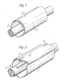
- Figure 1 shows a recoverable sheet 1, preferably recoverable over its entire surface, wrapped around a cable, a pipe or other conduit 2 with its longitudinal edges overlapping at 3, to form a tubular sleeve.
- a support which in this case is a rod 4, is inserted within the sleeve adjacent the overlap.
- Two fasteners 5 have been used to hold the recoverable material in its wrapped configuration while the installation is completed. These fasteners are not necessary for all but the largest sleeves, it being found that the sleeve can be held in position by hand while the remaining stages are carried out.
- Figure 3 shows an alternative way of proceeding at this stage : instead of fastening two layers of sheet together, all four can be fastened together to form a conduit 6-into which a rod 4 can subsequently be inserted.
- Two support rods 4 are used in the embodiment of Figure 4, one rod being positioned at each edge of the sleeve. This variation may be found preferable for thicker or less flexible sheet where the step of conforming a double thickness of sheet around a single rod may introduce undesirable craft-sensitivity.
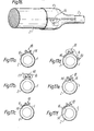
- Figures 4 and 5 each show a way of folding the sheet 1 which has a particular advantage.
- One edge of the sheet, after passing around the rod 4, is folded so as to form a central flap 7 which provides a smooth, closed interior under the closure, and in Figure 4 prevents a direct leak path (line 8 in Figure 9) existing between the two edges of the sheet.
- FIG. 6 Deformation of the overlapping region around the support is shown in Figure 6.
- the sheet takes on an Omega shape 6 in this region, although the precise cross-sectional shape will depend on the shape of the support 4.
- Deformation of the sheet around the support will generally be carried out substantially simultaneously with the installation of the fastening device, shown fully installed in Figure 7.
- the fastening device 9 is a channel, of generally C-shaped cross-section and having slots to increase its flexibility. The device 9 can be slid lengthwise onto the Omega-shaped ridge or it can be snapped on laterally.
- tubular sleeve 1 is preferably coated with a mastic or an adhesive, preferably a heat-activatable adhesive such as a hot-melt or an epoxy reactive system.
- a heat-activatable adhesive such as a hot-melt or an epoxy reactive system.
- the quality of the seal will also depend on where in the overlapping region the Omega-shaped ridge is made: a better seal is obtained if underlying flap 7 is larger and overlying flap 10 is smaller since flap 7 is forced against the adjacent sleeve due to the hoop stresses generated during recovery.
- each edge of the sheet is inserted into a closure device, and the closure devices are then interengaged.
- the steps of inserting the edges, wrapping the sheet around the substrate and interengaging the devices may be carried out in any order, although the order listed is preferred.
- the order which results in the production of a tubular product which is subsequently installed around the substrate is least preferred.
- Figure 10 illustrates in partial cross-section a pipe 2 around which has been wrapped a plain sheet 1.
- the opposing ends.14 and 16 of the plain sheet 1 have been inserted through a closure device 18 according to this invention thereby collectively providing a protective closure.
- the closure device 18 has a first frictional gripping element 20 and a second frictional gripping element 22.
- Each frictional gripping element 20, 22 has a channel member 24 (shown here as having but not being limited to an elliptical interior cross-section), which channel members 24 each have a slit 26 (shown as an elongate slit) extending along the entire length of said channel member 24.
- Each frictional gripping element 20 and 22 also has a rod member 28, which is at least as long as said gripping element 20 or 22 and which is positionable within said channel member 24 and when so positioned cooperates therewith to provide a conduit thereinbetween and to apply frictional forces to one end 14 or 16 of the plain sheet 1.
- the rod member 28 is shown here as having an elliptical cross-sectional shape so as to correspond to the elliptical cross-sectional shape of the interior of the channel member 24, but which is of smaller cross-sectional area so that the plain sheet 1 is insertable, but is frictionally gripped by an effective frictional fit.
- the rod member 28 may be placed within the channel member 24 and the sheet end 16 inserted through the slit 26 and around the rod member 28, the insertion operation aided by rotating the rod member 28 to help advance the sheet therethrough.
- the sheet end 16 may be folded over to form a loop, the loop inserted directly through the slit 26 into the channel member 20 or inserted by sliding the channel member 20 sideways over the looped sheet, followed by pushing the rod member 28 through the loop created by folding the sheet end 16.
- the sheet end 16 may be folded over the rod member 28 and that subassembly pushed or snapped through said slit 26 together.
- Figure 10 also shows the gripping elements 20 and 22 as being connected by an integral connecting bridge 30 extending from the outer surface of the first gripping element 20 to the outer surface of the second gripping element 22, thus providing a means for interengaging the gripping elements 20 and 22.
- the integral connecting bridge 30 permanently joins and holds the gripping elements 20 and 22 in a fixed spatial relationship.
- the gripping elements 20 and 22 may have means for interengaging which do not permanently join the elements, but which allow the elements to be engaged and thereby placed in a fixed spatial relationship, or disengaged at will. The ability to disengage and to subsequently re-engage is an asset for protective closure applications where re-entry is advantageous.
- the closure devices 18 of this invention are capable of holding together the opposing ends of plain sheets 1, which may be but are not limited to, polymeric sheets, dimensionally-recoverable polymeric sheets, (i.e. those which have a shape memory, such as those which are heat-shrinkable from a stretched heat-unstable configuration to a remembered heat-stable configuration), an elastomeric sheet such as neoprene, a sheet of metal, a foraminous sheet, a foraminous sheet having laminated thereto one or more sheets of polymeric material, a foraminous sheet such as a fabric sheet of woven fiber glass which has been impregnated, for example, with an organic material, or a laminated sheet composed of one or more layers in combination of any of the foregoing.
- plain sheets 1 may be but are not limited to, polymeric sheets, dimensionally-recoverable polymeric sheets, (i.e. those which have a shape memory, such as those which are heat-shrinkable from a stretched heat-unstable
- Wrap- around sleeves of these materials are generally used as protective closures for environmentally sealing, electrically insulating and/or strengthening a pipe, conduit, or cable, and as such generally have layers of mastic or adhesive, such as a hot-melt adhesive coated thereon. Although not shown in the drawing, use of such mastic or adhesive layers is contemplated by this invention.
- the frictional force requirements will vary with the user's application specifications and/or the materials used. Hence it is recognized that the frictional gripping elements of this invention must be and are tailorable to the user's application.
- the geometries of the closure device elements, the materials used in fabrication (metals or polymers, for example) and the textures of the surfaces of the various elements, are examples of variable design factors.
- Figure 11 illustrates in cross-section one of the interengagable closure devices 18 according to this invention which may be disengaged.
- the gripping elements 20 and 22 have channel members 24 which are shown as circular in cross-section and which have slits 26 extending the length thereof.
- the rod members 28 are shown as having a circular cross-section and are hollow. This is expecially valuable when the rod members 28 or the entire closure device 18 is fabricated from a polymeric material, because the hollow rod members 28 may then be quite flexible, which advantage will be discussed later.
- the means for interengaging the gripping elements 20 and 22 is a mateable clasp 32 (shown as but not limited to being an elongate clasp) having a first clasp portion 34 and a second clasp portion 36, which portions are bent in opposing senses to one another.
- the first clasp portion 34 extends from the outer surface of the first gripping element 20 toward the second gripping element 22 and bends upwardly away from the elongate substrate at its tip 38.
- the second clasp portion 36 extends from the outer surface of the second gripping element 22 toward the first gripping element 20 and bends downwardly toward the elongate substrate at its tip 40. When interengaged these two clasp portions (34, 36) form the mateable clasp 32.
- this clasp 32 if fabricated from appropriate materials, such as a metal which yields, may be crimped at one or more points along its length, thereby permanently joining and holding said gripping elements 20 and 22 in a fixed spatial relationship. Crimping renders the installation permanent, the closure device 18 no longer being disengageable.
- Figure 11B is a top view of the closure device shown in Figure 2A.
- the rod members 28 are shown as extending beyond the extremities of the gripping elements 20 and 22 to demonstrate that the closure devices 18 may be used for more than just a narrow plain sheet or band. Every embodiment of these closure devices 18 may be fabricated to accommodate, with reference to the elongate substrate, plain sheets 1 having any longitudinal width and any circumferential length. It is preferable that the entire length of each end of the opposing sheet ends be in contact with a rod member 28, most preferably the same rod member 28. Where one closure device 18 extends the full longitudinal width of the sheet ends, the rod member 28 will also extend the full longitudinal width.
- a mateable latch 42 provides the means for interengaging the first frictional gripping element 20 and the second frictional gripping element 22.
- a first latch portion 44 extends from the outer surface of the channel member 24 of the first gripping element 20 toward the second gripping element 22, bends upwardly away from the elongate substrate at its tip 46 and has one notch 48 along its length.
- the second latch portion 50 extends from the outer surface of the channel member 24 of the second gripping element 22 toward the first gripping element 20 and has a neck portion 52 and a bar member 54.
- the neck portion 52 extends from the outer surface of the second gripping element 22 and perpendicularly joins the bar member 54 to form a T.
- the neck portion 48 of the second latch portion 50 is adapted to slide through the notch 48 in the first latch portion 44.
- a plurality of such mateable latches may be desireable for each closure device. For shorter closure devices 18 having lengths on the order of 5cm (about 2 inches), one mateable latch 42 is believed sufficient for most applications.
- the rod members 28 are shown as having equilaterally triangular cross-sections.
- Such a non-circular rod member geometry when combined with a channel member 24 having a circular interior cross-section, for example, increases the frictional forces that a plain sheet inserted through the closure device 18 experiences. The same increase in frictional forces is expected when rod members having circular cross-sections are combined with channel members having non-circular interior cross-sections.
- Other combinations of geometries are contemplated by this invention although and hence these examples are not to be considered limitating.
- the elliptical rod member of Figure 10 is a low profile shape and is especially suited for elastomeric sheet materials or others which may be cinched-up, which cinching-up is is accomplished by pulling the sheet tautly through the closure device 18.
- the triangular rod member shown in Figure 12, or any other cross-sectional shape characterized by angularity, such as, a hexagon, a square, a rectangle, a right triangle, or even a generally round rod member having an axial undercut (shown in Figure 15), etc., may be employed to increase the frictional forces to which the plain sheet inserted through the closure device 18 is subjected.
- Frictional forces may also be increased by texturing the inner surface of the channel member 24 or by texturing the exterior of the rod member 28, such as by scoring with longitudinal grooves, knurling or scoring a cross-hatched pattern, coating these surfaces with a high-frictional material such as a rubbery elastomer, or gluing or laminating to the surfaces a high-frictional material such as a Velcro (Trade Mark) layer (not shown).
- a high-frictional material such as a rubbery elastomer
- Velcro Trade Mark
- Figure 13 is a cross-sectional view of yet another closure device 18 according to this invention.
- Stiffening members 25 are shown extending from the outer surfaces of the channel members 24.
- the means for interengaging the first gripping element 20 and the second gripping element 22 is an interdigitating or hinge joint, having interdigitatable, spaced segments, which have a longitudinal channel therethrough, and a pin 58 insertable through said channel.
- the first gripping element 20 is shown as having two spaced segments 60 attached to the outer surface of its channel member 24 which faces the second gripping element 22, although any number of segments is contemplated. These segments 60 extend in a direction which is parallel to the slit 26.
- the second gripping element 22 is shown as having one spaced segment 62 attached to the outer surface of its channel member 24 which faces the first gripping element 20, although any number of segments is contemplated.
- the segment 62 extends in a direction which is parallel to the slit 26, the spacing of the segments 60, (shown here as but not limited to cylindrical segments), allowing interdigitation thereof and allowing permanent engagement in a fixed spatial relationship by insertion of pin 58 therethrough.
- Figure 13 is a top view of the closure device shown in Figure 13.
- the slit 26 may be 0.632cm (about 1/4 inch) wide
- the inside diameter of the channel member 24 may be 1.27cm (about 1/2 inch)
- the outside diameter of the rod member 28 may be 0.632cm (about 1/4 inch).
- a male member 66 extends from the outer surface of the channel member 24 of the gripping element 20 toward the gripping element 22.
- the channel member 24 is shown as having been machined in a block of polymeric material, although a variety of materials and fabrication methods are contemplated by this invention.
- the male member 66 has a protuberance 67 with a barb 68, which barb 68 impedes the removal of the male member 66 once it is interengaged with a female member 70.
- the female member 70 has a cavity 71 with a constricted aperature 72, through which the protuberance 67 and its barb 68 barely pass, (i.e. a press-fit) and which constricted aperature 72 cooperates with the barb 68 of the male member 66 to impede the removal of the male member 66 once it is interengaged with the female member 70.
- the cavity 71 is shown as a generally rectangular box having a rectangular aperature 72. It could be a longitudinal groove extending parallel to the slit 26 and having a length of up to the length of said slit 26. Alternatively it could take other shapes.
- the male member 66 is shown as a wide rectangular protuberance 67 with a barb 68. It's width could extend the length of the slit 26. It also could assume other shapes provided that they are compatible with the female member 70.
- the rod members 28 are shown as having generally circular cross-sections, but with an axial undercut 74 as previously dicussed, for the purpose of increasing the frictional forces to which the plain sheet inserted through the closure device 18 is subjected. More than one axial undercut 74 may be employed for each rod member 28. These axial undercuts 74 will generally extend substantially along the entire length of the rod member 28.
- Figure 14 is a top view of the closure device 18 shown in Figure 14.
- One snap-lock closure 64 is shown although more than one snap-lock closure for each closure device may be advisable for some applications, such as when the closure device has a long length.
- a top plan view of a pair of closure devices 18 and 18' according to this invention are shown with long rod members 28 having variable diameters.
- the slits 26 of the channel members 24 have one contoured edge 76, shown better in Figure 15, although one or the other or both of the edges of each slit 26 may be contoured.
- the shape defined by the edge contour shown in Figure 15 as a curved rectangular shape, is such that it coordinates with the shape defined by the rod member 28 having a variable diameter, shown in Figure 15, for example, as spaced cylinders 78 along a rod of smaller diameter.
- the diameter of the rod members 28 at their widest point exceeds the width of the slit 26 at its widest point and hence the rod members 28 in this embodiment are not insertable directly through the slits 26, but rod members 28 may be inserted laterally through the contoured edges 76 of the gripping elements 20 and 22 respectively. Once inserted, the rod members 28 may be advanced longitudinally within the channel members 24 to a point where they cannot be laterally removed, thereby insuring retention.
- Each end 14, 16 of the plain sheet may be folded around a rod member 28 and inserted laterally by pushing the subassembly through the contoured edge 76 and into the channel member 24.
- each sheet end 14, 16 may be inserted through the slit 26 of the channel member 24 after the rod member 28 has been inserted laterally through the contoured edge 76 and is already present within the channel member 24, and inserted around said rod member 28, optionally assisted by rotating the rod member 28.
- each sheet end 14, 16 may be inserted through the slit 26 by first folding the sheet end over to form a loop. Once the looped sheet end is present in the channel member 24, a rod member 28 may be pushed or pulled through the subassembly.
- the term "inserted" is meant to include any of the foregoing acts or combination of acts.
- Figure 15 is a cross-sectional view of the pair of closure devices 18 of Figure 15.
- the means for interengaging the gripping elements 20 and 24 is shown as a mateable clasp 32 as shown and discussed previously for Figure 11, although any of the clasps according to this invention could probably be used interchangably for most applications.
- the clasps shown are optionally crimpable as previously discussed.
- FIG. 16 shown is a perspective view of a plurality of the closure devices 18 according to this invention holding together the opposing ends of a plain sheet 1 which has been wrapped around a pipe 2 having a large transition in diameter.
- the ends of sheet 1 were inserted through the first and second frictional gripping elements 20 and 22 respectively, of each closure device 18 either by folding the end around the rod member 28 and inserting it through the slit 26, or by folding the end and inserting it through the slit followed by the insertion of the rod member therethrough or by any other insertion method.
- the plain sheet 1 is then wrapped circumferentially around the elongate substrate, the pipe 2, and the respective first and second frictional gripping elements 20 and 22 for each closure device 18 are interengaged by means of any of the means of interengaging taught by this invention, i.e. clasps, latches, snap-locks, interdigitating joints, etc.
- the plain sheet 1 is caused to come into intimate contact with the pipe 2 by, for example, cinching-up on the sheet ends 14 and 16, accomplished by pulling them tautly through the closure devices 18.
- an elastomeric plain sheet 1 is employed as part of the protective closure
- the elastomeric sheet could have been previously stretched and the intimate contact with the pipe 2 achieved by allowing the elastomeric sheet to relax and shrink into intimate contact therewith.
- An example of the use of an elastomeric marterial for enclosing an elongate substrate such as a pipe can be found, for example, in U.S. Patent No. 4,135,553 to J.H. Evans et al, herein incorporated by reference.
- the plain sheet 1 is a dimensionally-recoverable polymeric material
- the plain sheet 1 may be caused to dimensionally- recover, for example, where the dimensionally-recoverable polymeric sheet is heat-shrinkable, the sheet may be caused to come into intimate contact with the pipe 2 by the application of heat.
- FIG 17 views A through F show in cross-section, a variety of ways in which a plain sheet 1 may be inserted through the closure devices 18 according to this invention.
- the insertion arrangement in Figure 17 is preferred for applications requiring that the sheet be cinchable, such as where a foraminous sheet (a woven fiberglass sheet) is used to bundle and strengthen a cable or conduit.
- a foraminous sheet a woven fiberglass sheet
- Figure 17 shows a most preferred method of inserting the sheet 1.
- Sheet end 14 has been underlapped, thereby protecting the elongate substrate underneath of the closure device 18.
- the opposing sheet end 16 is free and may be drawn over and around the closure device 18 as shown in Figure 17.
Landscapes
- Cable Accessories (AREA)
- Wrappers (AREA)
- Buffer Packaging (AREA)
- Packaging Of Annular Or Rod-Shaped Articles, Wearing Apparel, Cassettes, Or The Like (AREA)
- Basic Packing Technique (AREA)
- Making Paper Articles (AREA)
- Package Frames And Binding Bands (AREA)
- Clamps And Clips (AREA)
- Surgical Instruments (AREA)
- Vending Machines For Individual Products (AREA)
- Lining Or Joining Of Plastics Or The Like (AREA)
Applications Claiming Priority (2)
| Application Number | Priority Date | Filing Date | Title |
|---|---|---|---|
| US300522 | 1981-09-09 | ||
| US06/300,522 US4384906A (en) | 1981-09-09 | 1981-09-09 | Flat sheet closure and method |
Publications (2)
| Publication Number | Publication Date |
|---|---|
| EP0074280A2 true EP0074280A2 (fr) | 1983-03-16 |
| EP0074280A3 EP0074280A3 (fr) | 1984-12-27 |
Family
ID=23159456
Family Applications (1)
| Application Number | Title | Priority Date | Filing Date |
|---|---|---|---|
| EP82304743A Withdrawn EP0074280A3 (fr) | 1981-09-09 | 1982-09-09 | Elément de fermeture rétrécissable |
Country Status (9)
| Country | Link |
|---|---|
| US (1) | US4384906A (fr) |
| EP (1) | EP0074280A3 (fr) |
| JP (1) | JPS5859816A (fr) |
| AU (1) | AU8813782A (fr) |
| BR (1) | BR8205250A (fr) |
| ES (2) | ES8401686A1 (fr) |
| GB (1) | GB2108330A (fr) |
| MX (1) | MX165883B (fr) |
| NO (1) | NO823040L (fr) |
Cited By (7)
| Publication number | Priority date | Publication date | Assignee | Title |
|---|---|---|---|---|
| EP0116392A3 (en) * | 1983-01-06 | 1985-10-16 | Raychem Limited | Wrap-around recoverable article |
| EP0201922A1 (fr) * | 1985-05-17 | 1986-11-20 | RXS Schrumpftechnik-Garnituren GmbH | Connexion thermorétractable d'une rainure variable et d'un élément fermant |
| EP0223424A1 (fr) * | 1985-10-21 | 1987-05-27 | N.V. Raychem S.A. | Fermeture pour manchon sous forme d'enveloppe |
| EP0203497A3 (en) * | 1985-05-23 | 1988-10-12 | Siemens Aktiengesellschaft Berlin Und Munchen | Longitudinally split tubular envelope, particularly a cable sleeve, of shrinkable material |
| DE4032376A1 (de) * | 1990-10-12 | 1992-04-16 | Aei Ges Fuer Automatik Elektro | Schrumpfschlauch |
| WO1994027299A1 (fr) * | 1993-05-07 | 1994-11-24 | Raychem Corporation | Dispositif a introduction laterale destine a sceller un faisceau de fils |
| EP0693627A1 (fr) * | 1994-07-12 | 1996-01-24 | DSG Schrumpfschlauch GmbH | Ensemble pour attacher, guider et fixer des objets |
Families Citing this family (17)
| Publication number | Priority date | Publication date | Assignee | Title |
|---|---|---|---|---|
| ES528709A0 (es) * | 1983-01-06 | 1985-05-16 | Raychem Ltd | Un metodo de encerrar un substrato contorneado y un articulo contractil correspondiente. |
| US4499129A (en) * | 1983-10-14 | 1985-02-12 | Raychem Corporation | Partially recoverable closure |
| ES8607108A1 (es) * | 1984-04-06 | 1986-06-01 | Raychem Sa Nv | Recubrimiento termorrecuperable y procedimiento para recu- brir un objeto de forma generalmente alargada |
| US5236765A (en) * | 1984-04-06 | 1993-08-17 | Nv Raychem Sa | Heat-recoverable article |
| DE3720231A1 (de) * | 1987-06-18 | 1989-01-05 | Norres Geb Srimaharaj Siriwan | Vorrichtung zur verbindung zweier materialbahnen |
| ES2064501T3 (es) * | 1989-03-03 | 1995-02-01 | Rxs Schrumpftech Garnituren | Envuelta de contraccion en caliente. |
| SE464160B (sv) * | 1989-07-07 | 1991-03-11 | Jan Cederstroem | Anordning foer montering av lock paa kapslar till halvledarkretsar |
| US8349114B2 (en) * | 2005-02-28 | 2013-01-08 | Cary Green | Mug wrap |
| US9129494B2 (en) * | 2012-12-13 | 2015-09-08 | Southern Imperial, Inc. | Alarming pusher system |
| US9594226B2 (en) | 2013-10-18 | 2017-03-14 | Corning Optical Communications LLC | Optical fiber cable with reinforcement |
| US10993550B2 (en) | 2018-03-21 | 2021-05-04 | Fasteners For Retail, Inc. | Anti-theft retail merchandise pusher with remote alarm feature |
| US10885753B2 (en) | 2018-03-21 | 2021-01-05 | Fasteners For Retail, Inc. | Anti-theft device with remote alarm feature |
| US10985538B2 (en) * | 2018-05-25 | 2021-04-20 | Leoni Bordnetz-Systeme Gmbh | System and method for reducing air volume in a splitter |
| EP3945949B1 (fr) | 2019-04-05 | 2025-01-22 | Fasteners for Retail, Inc. | Pousseur antivol à détection de distance incrémentielle |
| US11154143B2 (en) | 2019-09-30 | 2021-10-26 | Fasteners For Retail, Inc. | Anti-theft hook with integrated loss prevention functionality |
| US12433428B2 (en) | 2021-08-23 | 2025-10-07 | Fasteners For Retail, Inc. | Anti-sweeping hook with integrated inventory monitoring and/or loss prevention functionality |
| US12437262B2 (en) | 2021-08-23 | 2025-10-07 | Fasteners For Retail, Inc. | Anti-sweeping hook with integrated inventory monitoring and/or loss prevention functionality |
Family Cites Families (28)
| Publication number | Priority date | Publication date | Assignee | Title |
|---|---|---|---|---|
| DE14263C (de) * | F. ZUR NEDDEN in Berlin SW., Grofsbeerehstr. 71 | Riemenverbinder | ||
| FR369278A (fr) * | 1906-08-28 | 1907-01-08 | Joseph Etienne Perrachon | Système d'agrafage pour courroies |
| FR561472A (fr) * | 1923-01-26 | 1923-10-23 | Agrafe pour courroie | |
| GB505013A (en) * | 1937-10-01 | 1939-05-01 | Valdemar Rendle | Improvements in resilient tubular coverings |
| DE1003314B (de) | 1955-03-21 | 1957-02-28 | Siemens Ag | Luftdichter Behaelter aus mehreren durch Loetung miteinander verbundenen Teilen, insbesondere laengs- oder quergeteilte Verbindungsmuffe |
| US3455336A (en) * | 1965-11-03 | 1969-07-15 | Raychem Corp | Heat recoverable article and process |
| US3542077A (en) * | 1968-05-22 | 1970-11-24 | Raychem Corp | Differentially cross-linked article and process for making the same |
| US3467761A (en) * | 1968-09-23 | 1969-09-16 | Walter A Plummer | Electrically shielded heat-reactive jacket for conductors |
| US3574313A (en) * | 1968-10-30 | 1971-04-13 | Raychem Corp | Wraparound closure sleeve |
| US3530898A (en) * | 1968-10-30 | 1970-09-29 | Raychem Corp | Closure sleeve |
| US3847721A (en) * | 1971-04-02 | 1974-11-12 | Raychem Corp | Heat recoverable articles and methods therefor |
| FR2151682A5 (en) * | 1971-09-08 | 1973-04-20 | Kleber Colombes | Looped transmission belt joint - with polyamide pins |
| DE2334429C2 (de) * | 1973-07-06 | 1982-07-15 | Felten & Guilleaume Energietechnik GmbH, 5000 Köln | Längsgeteilte Muffe für elektrische Kabel, insbesondere Verbindungs- oder Abzweigmuffe |
| US3910448A (en) * | 1974-05-31 | 1975-10-07 | Raychem Sa Nv | Heat recoverable closure assembly |
| DE7423507U (de) * | 1974-07-10 | 1974-11-14 | Siemens Ag | Kabelmuffe |
| CH583857A5 (en) * | 1975-05-17 | 1977-01-14 | Utzinger Valentin | Sheet securing clip for rectangular component - bears against three sides and snaps over fourth with resilient action |
| GB1561125A (en) * | 1975-08-04 | 1980-02-13 | Raychem Sa Nv | Heat recoverable article |
| GB1545571A (en) * | 1976-01-22 | 1979-05-10 | Post Office | Dimensionally heat-unstable products |
| JPS5357278A (en) * | 1976-11-05 | 1978-05-24 | Nippon Telegraph & Telephone | Method of adhesion of thermally shrinkable polyethylene sheet |
| US4083087A (en) * | 1977-04-12 | 1978-04-11 | Hale C Clark | Flexible pipe clamp assembly |
| GB1604439A (en) * | 1977-12-23 | 1981-12-09 | Raychem Pontoise Sa | Heat-recoverable wrap-around devices |
| GB1604440A (en) * | 1977-12-23 | 1981-12-09 | Raychem Sa Nv | Heatrecoverable wrap-around devices |
| GB1604983A (en) * | 1978-02-21 | 1981-12-16 | Raychem Sa Nv | Bracing method |
| FR2422275A1 (fr) * | 1978-04-07 | 1979-11-02 | Isolants Cie Fse | Gaine constituant enveloppe tubulaire retractable |
| DE2820181C3 (de) * | 1978-05-09 | 1981-08-20 | Siemens AG, 1000 Berlin und 8000 München | Verschluß für ein längsgeschlitztes Kabelmuffenrohr |
| GB2038924A (en) * | 1978-12-06 | 1980-07-30 | Raychem Corp | Heat Recoverable Closure Assembly and Method |
| EP0023418B1 (fr) * | 1979-07-27 | 1983-10-12 | A.C. Egerton Limited | Chemise pour l'enrobage d'un tuyau, d'un câble ou analogue |
| GB2069773B (en) * | 1980-02-08 | 1984-02-08 | Raychem Sa Nv | Recoverable closure assembly |
-
1981
- 1981-09-09 US US06/300,522 patent/US4384906A/en not_active Expired - Fee Related
-
1982
- 1982-09-08 BR BR8205250A patent/BR8205250A/pt unknown
- 1982-09-08 NO NO823040A patent/NO823040L/no unknown
- 1982-09-08 ES ES515563A patent/ES8401686A1/es not_active Expired
- 1982-09-08 MX MX194316A patent/MX165883B/es unknown
- 1982-09-08 AU AU88137/82A patent/AU8813782A/en not_active Abandoned
- 1982-09-09 JP JP57157942A patent/JPS5859816A/ja active Pending
- 1982-09-09 EP EP82304743A patent/EP0074280A3/fr not_active Withdrawn
- 1982-09-09 GB GB08225681A patent/GB2108330A/en not_active Withdrawn
-
1983
- 1983-09-30 ES ES526178A patent/ES8407255A1/es not_active Expired
Cited By (10)
| Publication number | Priority date | Publication date | Assignee | Title |
|---|---|---|---|---|
| EP0116392A3 (en) * | 1983-01-06 | 1985-10-16 | Raychem Limited | Wrap-around recoverable article |
| EP0272364A1 (fr) * | 1983-01-06 | 1988-06-29 | Raychem Limited | Procédé de fabrication d'un élément de fermeture pour un objet enveloppant rétractable |
| EP0427356A3 (en) * | 1983-01-06 | 1992-09-02 | Raychem Limited | Wrap-around recoverable article |
| EP0201922A1 (fr) * | 1985-05-17 | 1986-11-20 | RXS Schrumpftechnik-Garnituren GmbH | Connexion thermorétractable d'une rainure variable et d'un élément fermant |
| EP0203497A3 (en) * | 1985-05-23 | 1988-10-12 | Siemens Aktiengesellschaft Berlin Und Munchen | Longitudinally split tubular envelope, particularly a cable sleeve, of shrinkable material |
| EP0223424A1 (fr) * | 1985-10-21 | 1987-05-27 | N.V. Raychem S.A. | Fermeture pour manchon sous forme d'enveloppe |
| US4860799A (en) * | 1985-10-21 | 1989-08-29 | Raychem Corporation | Closure for wraparound sleeve |
| DE4032376A1 (de) * | 1990-10-12 | 1992-04-16 | Aei Ges Fuer Automatik Elektro | Schrumpfschlauch |
| WO1994027299A1 (fr) * | 1993-05-07 | 1994-11-24 | Raychem Corporation | Dispositif a introduction laterale destine a sceller un faisceau de fils |
| EP0693627A1 (fr) * | 1994-07-12 | 1996-01-24 | DSG Schrumpfschlauch GmbH | Ensemble pour attacher, guider et fixer des objets |
Also Published As
| Publication number | Publication date |
|---|---|
| BR8205250A (pt) | 1983-08-16 |
| JPS5859816A (ja) | 1983-04-09 |
| ES526178A0 (es) | 1984-08-16 |
| ES8407255A1 (es) | 1984-08-16 |
| AU8813782A (en) | 1983-03-17 |
| ES515563A0 (es) | 1983-12-16 |
| ES8401686A1 (es) | 1983-12-16 |
| EP0074280A3 (fr) | 1984-12-27 |
| MX165883B (es) | 1992-12-08 |
| NO823040L (no) | 1983-03-10 |
| US4384906A (en) | 1983-05-24 |
| GB2108330A (en) | 1983-05-11 |
Similar Documents
| Publication | Publication Date | Title |
|---|---|---|
| EP0074280A2 (fr) | Elément de fermeture rétrécissable | |
| US4298415A (en) | Branch-off method | |
| EP0272364B1 (fr) | Procédé de fabrication d'un élément de fermeture pour un objet enveloppant rétractable | |
| EP0133337B1 (fr) | Revêtement thermorétractable | |
| US4219051A (en) | Heat recoverable article | |
| CA1136820A (fr) | Dispositifs enveloppants | |
| US4400579A (en) | Branch-off assembly | |
| CA2016862A1 (fr) | Manchon elastique a garniture interne enroulee pour raccorder hermetiquement les cables electriques | |
| CA1195265A (fr) | Enveloppe | |
| US4560828A (en) | Tubular article for branch-off seal | |
| CA2065743A1 (fr) | Joint universel | |
| CA1141921A (fr) | Gaine recuperable par la chaleur | |
| EP0042262A1 (fr) | Matériau plié à reprise | |
| EP0036306B1 (fr) | Fermeture d'une enveloppe en matière thermorétractable | |
| US5997967A (en) | Side entry device for sealing wire bundles | |
| GB1604986A (en) | Clip | |
| GB2095926A (en) | Branch-off method | |
| CA1051987A (fr) | Enveloppe et methode de scellement a la chaleur | |
| GB1604985A (en) | Branchoff method | |
| EP0147416A1 (fr) | Manchon retrecissable a la chaleur pour cables electriques et connexions de cables | |
| CA1177627A (fr) | Methode de piquage d'une derivation | |
| CA1156817A (fr) | Raccord a pince de branchement enveloppante et isolante | |
| CA1170685A (fr) | Bride souple sur t | |
| CA1206427A (fr) | Pellicule de recouvrement thermoretrecissable | |
| GB2107532A (en) | Branch-off method |
Legal Events
| Date | Code | Title | Description |
|---|---|---|---|
| PUAI | Public reference made under article 153(3) epc to a published international application that has entered the european phase |
Free format text: ORIGINAL CODE: 0009012 |
|
| 17P | Request for examination filed |
Effective date: 19821007 |
|
| AK | Designated contracting states |
Designated state(s): AT BE CH DE FR IT LI NL SE |
|
| PUAL | Search report despatched |
Free format text: ORIGINAL CODE: 0009013 |
|
| AK | Designated contracting states |
Designated state(s): AT BE CH DE FR IT LI NL SE |
|
| STAA | Information on the status of an ep patent application or granted ep patent |
Free format text: STATUS: THE APPLICATION IS DEEMED TO BE WITHDRAWN |
|
| 18D | Application deemed to be withdrawn |
Effective date: 19850628 |
|
| RIN1 | Information on inventor provided before grant (corrected) |
Inventor name: DE BLAUWE, FRANCIS JOSEF ANNA M.C. Inventor name: PARKER, ROBERT Inventor name: RATZLAFF, THOMAS D. Inventor name: MOLINARI, ROBERT J. |