EP0074418B1 - Machine à distribuer des liquides - Google Patents
Machine à distribuer des liquides Download PDFInfo
- Publication number
- EP0074418B1 EP0074418B1 EP19810107187 EP81107187A EP0074418B1 EP 0074418 B1 EP0074418 B1 EP 0074418B1 EP 19810107187 EP19810107187 EP 19810107187 EP 81107187 A EP81107187 A EP 81107187A EP 0074418 B1 EP0074418 B1 EP 0074418B1
- Authority
- EP
- European Patent Office
- Prior art keywords
- tank
- assemblies
- valve
- pump
- assembly
- Prior art date
- Legal status (The legal status is an assumption and is not a legal conclusion. Google has not performed a legal analysis and makes no representation as to the accuracy of the status listed.)
- Expired
Links
- 239000007788 liquid Substances 0.000 title claims description 3
- 230000000712 assembly Effects 0.000 claims description 41
- 238000000429 assembly Methods 0.000 claims description 41
- 239000000463 material Substances 0.000 claims description 3
- 238000004140 cleaning Methods 0.000 description 5
- XLYOFNOQVPJJNP-UHFFFAOYSA-N water Substances O XLYOFNOQVPJJNP-UHFFFAOYSA-N 0.000 description 4
- 238000007789 sealing Methods 0.000 description 2
- 238000004891 communication Methods 0.000 description 1
- 230000008878 coupling Effects 0.000 description 1
- 238000010168 coupling process Methods 0.000 description 1
- 238000005859 coupling reaction Methods 0.000 description 1
- 230000001419 dependent effect Effects 0.000 description 1
- 238000000034 method Methods 0.000 description 1
- 230000000737 periodic effect Effects 0.000 description 1
- 230000000717 retained effect Effects 0.000 description 1
- 238000011012 sanitization Methods 0.000 description 1
- 235000013618 yogurt Nutrition 0.000 description 1
Images


Classifications
-
- B—PERFORMING OPERATIONS; TRANSPORTING
- B65—CONVEYING; PACKING; STORING; HANDLING THIN OR FILAMENTARY MATERIAL
- B65B—MACHINES, APPARATUS OR DEVICES FOR, OR METHODS OF, PACKAGING ARTICLES OR MATERIALS; UNPACKING
- B65B3/00—Packaging plastic material, semiliquids, liquids or mixed solids and liquids, in individual containers or receptacles, e.g. bags, sacks, boxes, cartons, cans, or jars
- B65B3/26—Methods or devices for controlling the quantity of the material fed or filled
- B65B3/30—Methods or devices for controlling the quantity of the material fed or filled by volumetric measurement
- B65B3/32—Methods or devices for controlling the quantity of the material fed or filled by volumetric measurement by pistons co-operating with measuring chambers
- B65B3/323—Methods or devices for controlling the quantity of the material fed or filled by volumetric measurement by pistons co-operating with measuring chambers with measuring chambers travelling in an endless path
Definitions
- the invention relates to a machine in accordance with the preamble of claim 1.
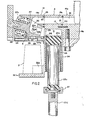
- the machine is shown as having a frame F supporting an upstanding sleeve 10 which has a flange 10a bolted to the frame at 11.
- Bearings 12 and 13 mounted by sleeve 10 journal a central shaff14 which is adapted to be driven by a spur gear 15 connected with any suitable source of rotary power.
- a tank mounting orbiting assembly supports a liquid-filled tank 16 for rotation with the shaft 14. Also mounted for rotation with the assembly are a plurality of pump assemblies A, pins 17 being provided to secure the pump assemblies A in place surrounding the outlet portion 16a as shown. It is to be understood that the outlet portion 16a has an outlet passage 18 and that the number of pump assemblies A depend on how many containers are to be supported on the machine and filled during the revolution of shaft 14.
- the passages 18 are in radial alignment with passages 18a provided in the pump assemblies A, which, as Figure 2 indicates, are sandwiched between a tank housing 16b and a plurality of valve assemblies 19 which are mounted radially outboard of each pump assembly A.
- seal rings 20 are provided around outlet passage 18 in slots 21 provided in each pump assembly A to seal passages 18 and 18a at the juncture of pump assemblies A and housings 16b', and circular seal rings 22 are provided in slots 23 in the valve assemblies 19 to seal the passages 18a and passages 19a provided in the valve assemblies 19 at the juncture of the valve assemblies 19 and pump assemblies A.
- Each pump assembly A includes a cylinder 24 with a piston 25.
- the piston head 25a is slotted to receive a sealing 0-ring 26.
- Each valve assembly 19 is provided with a frustoconically shaped recess R communicating with an associated passage 19a to receive a rotary frustoconical valve 27 which later will be more particularly described, and it will be seen that a pump cylinder 24 is positioned opposite each recess R and valve 27.
- Springs 27b retained by removable retainers 27a secured in the outer ends of the recesses R urge valves 27 inwardly and a sealing ring 27d is provided as shown.
- Openings 29 are provided in the radial outer wall of each pump cylinder 24, so that when a valve 27, with its port system 30, is in the position shown in Figure 2, it communicates the passage 19a with the filling passage 31 above piston head 25a via opening 29.
- Each port system 30 includes ports 30a and 30b, and a port 30e perpendicular to port 30b, and "in the Figure 2 position, ports 30a and 30b communicate passage 19a with cylinder 24.
- Each pump assembly A comprises a container supporting carrier 32 having a partly enclosing side wall 32a for supporting an open-topped yogurt container y which is in the position to be filled through a dispensing opening 33 provided above each carrier 32 in communication with each valve recess R.
- valve 27 when the valve 27 is rotated approximately 90° from the suction position in which it is shown in Figure 2, port 30e of angle shaped port system 30 will communicate with the dispensing opening 33 and deliver material ejected by the pump piston 25 through opening 29 and port 30b to dispensing opening 33 via port 30e.
- valve assemblies 19 Mounted below valve assemblies 19 are a pair of semicircular, detachable, orbiting, condensate collecting and spill trays 34, each having passages 34a beneath each opening 33 formed by riser walls 35 which are of greater height than the tray outer lips 36.
- each piston 25 includes an upper stem part 25b and a lower stem part 25c, joined by a coupling 37.
- the rotatable tank-supporting annulus cage C which is journaled by a bearing 39, includes a top plate 41 to which an under plate 42 is bolted as at 43. Under plate 42 is bolted to the annular cage C as at 44. Depending from plate 42 is the flange 40 which is welded to shaft 14 and may be bolted to plate 42 as at 45. A pin 46 centrally disposed in openings 47, 48 and 49 in underplates 42, top plate 41 and in tank housing 16b, respectively, is provided as shown to aid in locating the parts for assembly.
- a guide ring 50 bolted to the cage C intermediate its length as at 51, mounts slide bearings 52 vor the lower stem parts 25c of pistons 25 and a further guide ring 53 with slide bearings 54 for the lower stem parts 25c is also provided.
- Figure 1 shows a pump piston 25 in both an upper and lower position.
- a follower roller 55 received within a recessed guideway 56 formed in cage C.
- Each roller 55 is mounted on a threaded stem 55a received in a threaded opening 57 provided in a block 58 fixed to the lower stem part 25c of each piston 25.
- each piston 25 at any time is determined by the vertical position of a follower 59 which is mounted in a block 60 dependent from each block 58.
- the vertical position of each roller 59 is influenced by either an upper arcuate cam part 61 or a lower annular cam part 62.
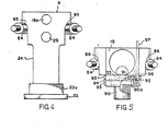
- FIGS. 3 through 5 particularly indicate the manner in which the assemblies 19 and A are supported by the tank housing 16b in the manner which permits them to be easily dis-assembled. It will be observed that the outer perimeter of housing 16b is a fourteen-sided polygon and it will further be observed that threaded openings 83 are provided in the housing 16b to accommodate mounting stud members 84.
- the pump assemblies A in front elevation are substantially T-shaped and include converging recesses 85 with which the pump assemblies A are suspended on stud members 84.
- the valve assemblies 19, which are also generally T-shaped in front elevation have converging recesses 86 to similarly suspend the valve assemblies 19 on the stud members 84.
- Clamp washers 87 provided on the stud members 84 may be secured by nuts 88 within recesses formed by shoulders 19c of the valve assemblies 19.
- Clamp washers 87 have wedge walls 87a which engage with similarly inclined walls 89 of the valve assemblies 19 to clamp the valve assemblies 19 and the pump assemblies A securely in position.
- each plug 90 includes a shoulder portion 90a snugly fitting into opening 91 and has an O-ring or other suitable seal 92, as shown.
- outboard walls 93 thereon have bayonet slots 94 for receiving pins 95 provided on the valve assemblies 19 and the plugs 90 are twisted to engage the pins 95 in the slots as the plugs 90 are moved into position.
- a passage 96 Leading upwardly from each valve assembly 19 from plug receiving opening 91, is a passage 96 leading to a tube 97. Tube 97, as indicated in Figure 1 leads back into tank 16.
- each of the openings 91 in each valve assembly 19 is fitted with a plug 90 and water introduced through the tube 98 into the interior of tank 16 is then re-circulated through the pump assemblies A and valve assemblies 19 back to the tank 16 via passages 96 and tubes 97.
- Only one tube 97 has been shown in Figure 1 but it is to be understood that each of the valve assemblies 19 may have a tube 97 or that a manifold (not shown) can be provided to which passages 96 lead and that a single tube may then lead from it back into tank 16.
- a water flush has been accomplished, one of the valves 27 can be removed to drain the water from the system. Thereafter the process can be repeated with a sanitized cleaning solution, and suitable water and cleaning solution flushes can be alternated until the desired sanitary cleaning has been accomplished.
Landscapes
- Engineering & Computer Science (AREA)
- Mechanical Engineering (AREA)
- Reciprocating Pumps (AREA)
Claims (3)
caractérise en ce que
Priority Applications (2)
| Application Number | Priority Date | Filing Date | Title |
|---|---|---|---|
| EP19810107187 EP0074418B1 (fr) | 1981-09-11 | 1981-09-11 | Machine à distribuer des liquides |
| DE8181107187T DE3174318D1 (en) | 1981-09-11 | 1981-09-11 | Liquid dispensing machine |
Applications Claiming Priority (1)
| Application Number | Priority Date | Filing Date | Title |
|---|---|---|---|
| EP19810107187 EP0074418B1 (fr) | 1981-09-11 | 1981-09-11 | Machine à distribuer des liquides |
Related Child Applications (4)
| Application Number | Title | Priority Date | Filing Date |
|---|---|---|---|
| EP85106919.5 Division-Into | 1981-09-11 | ||
| EP85106919A Division EP0159051A3 (fr) | 1981-09-11 | 1981-09-11 | Machine pour distribuer du matériau liquide et semi-liquide |
| EP85106918A Division EP0162480A3 (fr) | 1981-09-11 | 1981-09-11 | Dispositif pour distribuer des matériaux liquides ou semi-liquides |
| EP85106918.7 Division-Into | 1981-09-11 |
Publications (2)
| Publication Number | Publication Date |
|---|---|
| EP0074418A1 EP0074418A1 (fr) | 1983-03-23 |
| EP0074418B1 true EP0074418B1 (fr) | 1986-04-09 |
Family
ID=8187902
Family Applications (1)
| Application Number | Title | Priority Date | Filing Date |
|---|---|---|---|
| EP19810107187 Expired EP0074418B1 (fr) | 1981-09-11 | 1981-09-11 | Machine à distribuer des liquides |
Country Status (2)
| Country | Link |
|---|---|
| EP (1) | EP0074418B1 (fr) |
| DE (1) | DE3174318D1 (fr) |
Families Citing this family (4)
| Publication number | Priority date | Publication date | Assignee | Title |
|---|---|---|---|---|
| IT1253474B (it) * | 1991-09-25 | 1995-08-08 | Rossi & Catelli Spa | Dosatrice volumetrica rotativa asettica |
| IT1308969B1 (it) * | 1999-01-05 | 2002-01-15 | Mg 2 Spa | Macchina per il dosaggio di prodotti farmaceutici liquidi. |
| ITBO20040630A1 (it) * | 2004-10-14 | 2005-01-14 | Marchesini Group Spa | Macchina per il riempimento in continuo di contenitori con prodotti liquidi |
| CN114652163B (zh) * | 2022-04-18 | 2024-02-13 | 安徽省万爱电器科技有限公司 | 一种智能移动式的净水茶吧 |
Family Cites Families (5)
| Publication number | Priority date | Publication date | Assignee | Title |
|---|---|---|---|---|
| US2958346A (en) * | 1958-01-28 | 1960-11-01 | Fmc Corp | Filling machine |
| FR1588001A (fr) * | 1968-10-18 | 1970-04-03 | ||
| US3744212A (en) * | 1971-06-17 | 1973-07-10 | Koehring Co | Automatic plastic bottling system and method |
| GB1383346A (en) * | 1972-04-05 | 1974-02-12 | Mather & Platt Ltd | Filling devices |
| US4060109A (en) * | 1976-05-14 | 1977-11-29 | Kewpie Kabushiki Kaisha | Filling quantity regulating system in container filling apparatus |
-
1981
- 1981-09-11 DE DE8181107187T patent/DE3174318D1/de not_active Expired
- 1981-09-11 EP EP19810107187 patent/EP0074418B1/fr not_active Expired
Also Published As
| Publication number | Publication date |
|---|---|
| DE3174318D1 (en) | 1986-05-15 |
| EP0074418A1 (fr) | 1983-03-23 |
Similar Documents
| Publication | Publication Date | Title |
|---|---|---|
| EP0497830B1 (fr) | Dispositif de mise en contact continue de liquides et de solides | |
| US6026867A (en) | Rotary filling machine | |
| EP0265128A2 (fr) | Remplissage de récipients d'emballage | |
| FI91544B (fi) | Paperimassan käsittelylaite ja menetelmä paperimassan käsittelyn suorittamiseksi | |
| US10130110B2 (en) | Depositing machine having a plug-in connection | |
| FI90001B (fi) | Foerfarande foer framstaellning av ost och ostpress | |
| CN109279558A (zh) | 一种液体药品灌装机 | |
| EP0246707B1 (fr) | Appareil pour injecter de la viande avec une substance, en particulier une substance à consistance pâteuse | |
| CN109589019B (zh) | 投料结构及调味机 | |
| US4414036A (en) | Sanitizer system and sanitizing method for carbonated beverage container filler machine | |
| US5431198A (en) | Apparatus and method of operation for a product filler machine | |
| CN102700771A (zh) | 充填机 | |
| US3601288A (en) | Volumetric drawing-off rotary apparatus | |
| US3105525A (en) | Machine and method for filling containers | |
| EP0074418A1 (fr) | Machine à distribuer des liquides | |
| EP0162480A2 (fr) | Dispositif pour distribuer des matériaux liquides ou semi-liquides | |
| EP0029634A1 (fr) | Pompe doseuse à piston pour fluides | |
| US1878277A (en) | Machine for washing ball bearings | |
| US4840205A (en) | Method and apparatus for dispensing liquids | |
| CN109452890B (zh) | 投料模块及调味机 | |
| US5108268A (en) | Pumps | |
| CN112429691A (zh) | 一种茶油生产用定量灌装装置 | |
| CA1167810A (fr) | Pompe sanitaire volumetrique a cylindree variable pour liquide | |
| CA1158616A (fr) | Pompe volumetrique a debit variable pour liquides sanitaires | |
| EP0159051A2 (fr) | Machine pour distribuer du matériau liquide et semi-liquide |
Legal Events
| Date | Code | Title | Description |
|---|---|---|---|
| PUAI | Public reference made under article 153(3) epc to a published international application that has entered the european phase |
Free format text: ORIGINAL CODE: 0009012 |
|
| AK | Designated contracting states |
Designated state(s): DE FR GB SE |
|
| 17P | Request for examination filed |
Effective date: 19830812 |
|
| GRAA | (expected) grant |
Free format text: ORIGINAL CODE: 0009210 |
|
| AK | Designated contracting states |
Kind code of ref document: B1 Designated state(s): DE FR GB SE |
|
| REF | Corresponds to: |
Ref document number: 3174318 Country of ref document: DE Date of ref document: 19860515 |
|
| ET | Fr: translation filed | ||
| PLBE | No opposition filed within time limit |
Free format text: ORIGINAL CODE: 0009261 |
|
| STAA | Information on the status of an ep patent application or granted ep patent |
Free format text: STATUS: NO OPPOSITION FILED WITHIN TIME LIMIT |
|
| 26N | No opposition filed | ||
| PG25 | Lapsed in a contracting state [announced via postgrant information from national office to epo] |
Ref country code: DE Effective date: 19870602 |
|
| PG25 | Lapsed in a contracting state [announced via postgrant information from national office to epo] |
Ref country code: SE Effective date: 19870912 |
|
| PG25 | Lapsed in a contracting state [announced via postgrant information from national office to epo] |
Ref country code: FR Free format text: LAPSE BECAUSE OF NON-PAYMENT OF DUE FEES Effective date: 19880531 |
|
| GBPC | Gb: european patent ceased through non-payment of renewal fee | ||
| REG | Reference to a national code |
Ref country code: FR Ref legal event code: ST |
|
| PG25 | Lapsed in a contracting state [announced via postgrant information from national office to epo] |
Ref country code: GB Free format text: LAPSE BECAUSE OF NON-PAYMENT OF DUE FEES Effective date: 19881121 |
|
| EUG | Se: european patent has lapsed |
Ref document number: 81107187.7 Effective date: 19880906 |