EP0074424B1 - Transducteur électroacoustique, en particulier électrodynamique, protégé contre l'humidité et la poussière, en particulier la poussière de fer - Google Patents
Transducteur électroacoustique, en particulier électrodynamique, protégé contre l'humidité et la poussière, en particulier la poussière de fer Download PDFInfo
- Publication number
- EP0074424B1 EP0074424B1 EP81107229A EP81107229A EP0074424B1 EP 0074424 B1 EP0074424 B1 EP 0074424B1 EP 81107229 A EP81107229 A EP 81107229A EP 81107229 A EP81107229 A EP 81107229A EP 0074424 B1 EP0074424 B1 EP 0074424B1
- Authority
- EP
- European Patent Office
- Prior art keywords
- sound
- transducer
- diaphragm
- plate
- plates
- Prior art date
- Legal status (The legal status is an assumption and is not a legal conclusion. Google has not performed a legal analysis and makes no representation as to the accuracy of the status listed.)
- Expired
Links
Images



Classifications
-
- H—ELECTRICITY
- H04—ELECTRIC COMMUNICATION TECHNIQUE
- H04R—LOUDSPEAKERS, MICROPHONES, GRAMOPHONE PICK-UPS OR LIKE ACOUSTIC ELECTROMECHANICAL TRANSDUCERS; ELECTRIC HEARING AIDS; PUBLIC ADDRESS SYSTEMS
- H04R9/00—Transducers of moving-coil, moving-strip, or moving-wire type
- H04R9/02—Details
-
- H—ELECTRICITY
- H04—ELECTRIC COMMUNICATION TECHNIQUE
- H04R—LOUDSPEAKERS, MICROPHONES, GRAMOPHONE PICK-UPS OR LIKE ACOUSTIC ELECTROMECHANICAL TRANSDUCERS; ELECTRIC HEARING AIDS; PUBLIC ADDRESS SYSTEMS
- H04R1/00—Details of transducers, loudspeakers or microphones
- H04R1/08—Mouthpieces; Microphones; Attachments therefor
- H04R1/083—Special constructions of mouthpieces
- H04R1/086—Protective screens, e.g. all weather or wind screens
-
- H—ELECTRICITY
- H04—ELECTRIC COMMUNICATION TECHNIQUE
- H04R—LOUDSPEAKERS, MICROPHONES, GRAMOPHONE PICK-UPS OR LIKE ACOUSTIC ELECTROMECHANICAL TRANSDUCERS; ELECTRIC HEARING AIDS; PUBLIC ADDRESS SYSTEMS
- H04R2410/00—Microphones
- H04R2410/07—Mechanical or electrical reduction of wind noise generated by wind passing a microphone
Definitions
- the invention relates to an electroacoustic transducer of the type specified in the preamble of claims 1 and 7.
- a known transducer of this type (DE-PS 1 172 729) had to protect the membrane against moisture, dust and.
- Protective device provided a housing consisting of two shells individually fastened to the converter housing, in which a catch plate fastened coaxially to the membrane was arranged on the inner shell. Both housing shells had holes in the area of a circular surface coaxial to the catch plate, the diameter of which was smaller than that of the catch plate.
- Another embodiment of this known transducer had two shells facing one another with their raised sides and firmly connected in the middle in front of the membrane.
- the shell adjacent to the membrane was provided with holes and connected at the edge to the membrane's edge fastening.
- a pair of cylinder rings was arranged so that one ring of each pair protruded between the two rings of the other pair.
- the protective devices of these known transducers were complex to produce and also had the disadvantage that foreign bodies which had penetrated the detour could not be removed.
- the effectiveness of the protective device was also limited: in the event of strong vibrations, all of the dust particles or drops of liquid that could accumulate could reach the membrane.
- the object is achieved to create a sound transducer of the type specified in the preamble, which is easier to manufacture, and its protective effect against moisture and dust, in particular iron dust, increased significantly without significant increase in effort and the Detour can be cleaned in the simplest way from the retained dust.
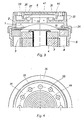
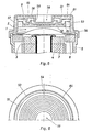
- 1 denotes the transducer membrane, 2 the space in front of the membrane 1, 3 the voice coil and 4 the core, 5 the jacket, 6 the bottom (not shown in FIGS. 1, 3 and 5), 7 the core pole and 8 the Ring pole of the pot magnet system of the electro-dynamic sound transducer.
- an outer (upper, facing away from the transducer system 1 and 3-8) and an inner (adjacent to the transducer system) plastic plate are arranged in front of the membrane 1, which are shown in FIG. 1 with 11 and 12, in FIG. 3 with 31 and 32, in Fig. 5 with 51 and 52, in Fig. 7 with 71 and 72 and in Fig. 9 with 91 and 92.
- the inner plate 12, 32 and 52 has an up and down projecting annular cylindrical collar 13, 33 and 53, in which the outer plate 11, 31 and 51 is inserted, and the has an attachment 14, 34 and 54 in the form of a profile ring at the bottom on the edge of the magnet system jacket 5.
- a ring of outer sound passages 19 in the upper part of the collar 13 forms Sound recording a sound inlet in the room 9 and / or for sound reproduction a sound outlet from the room 9, which is connected to the room 2 in front of the membrane 1 through a central sound passage 21 of the inner plate 12. A deflection is also forced at the edge of the passage 21 formed by the projection 18.
- the plate 12 has on its side facing away from the membrane 1 to the membrane 1 concentric grooves 23, in which liquid drops and dust particles, which were prevented by the detour from reaching the sound passage 21, so that they do not over vibrate the projections 17 and 18 can reach.
- Iron dust particles are held in these grooves 23 by the stray field of the magnet system 4-8. Because the dust particles accumulate in the grooves 23, they also form a smaller part of the boundary surface of the intermediate space 9 and increase its acoustic resistance less than an evenly distributed dust coating that would arise without the grooves 23.
- Grooves 24, which run concentrically to the transducer system, on the outside of the outer plate 11 also receive liquid drops and dust particles reaching them, so that they cannot reach the sound passages 19 via the edge thereof.
- FIGS. 3 and 4 differs from that according to FIGS. 1 and 2 in that the ring of outer sound passages is formed from holes 39 of the outer plate 31 which are parallel to the axis of the transducer system. Because this already results in a deflection at the transition from these holes 39 to the intermediate space 9, a projection 35 on the plate 31 together with two projections 37, 38 on the plate 32 are sufficient. Otherwise, 33, 34, 41, 43 and 44 are equivalent 13, 14, 21, 23 and 24 in FIGS. 1 and 2. However, the grooves 44 in FIGS. 3 and 4 are of increased importance because dust particles deposited on the outside of the plate 31 get particularly easily into the sound passages 39 without these grooves 44 could.
- the embodiment according to FIGS. 5 and 6 has a single central outer sound passage opening 59 and a ring of inner sound passages 61 for connecting the rooms 9 and 2. As a result, other acoustic properties of the detour can be achieved.
- the annular projections 55-58 and the grooves 63 and 64 correspond to 15-18, 23 and 24 in FIGS. 1 and 2, and 35, 37, 38, 43, 44 in FIGS. 3 and 4. -
- a ring of outer sound passages 79 and a central sound passage 80 are provided in the outer plate 71 and the intermediate space 9 between the plates 71 and 72 is with the space 2 in front of the membrane 1 through a ring of holes 81 in connected to the plate 72, which in the example shown runs approximately in the middle between the sound passages 79 and the sound passage 80.
- This forms a detour from the rim 79 to the rim 81 and a second detour from the passage 80 to the rim 81.
- a first detour is formed, similarly to FIG. 3 (cf. also FIG. 7), in that a ring of outer, but in FIGS. 9 and 10, elongated sound passage openings 99 into the intermediate space 9 between the plates 91 and 92 leads.
- a second detour is formed in that a central, inner sound passage opening 101 in the plate 92 has an edge 97 projecting into the space 9 and an edge 105 projecting into the space 2, which is offset somewhat outwards with respect to the edge 97, so that the sound passage 101 is expanded towards the membrane 1.
- the edge 105 encloses a plate 106 with an upwardly projecting edge 107 which is supported on projections 108 of the plate 92.
- the path of drops and dust particles to the passage 101 is limited to spaces between webs 109, which consist of parts formed on the plates 91 and 92.
- the grooves 103 and 104 have the effects mentioned in connection with the corresponding grooves of the other embodiments.
- both plates e.g. B. the plates 11,12 in Fig. 1, detachable from each other and from the rest of the transducer.
- the plate 11 can have an external thread on the circumference
- the upper collar part 13 an internal thread
- the profile ring 14 an internal thread
- the upper edge of the magnet system jacket 5 have an external thread.
Landscapes
- Physics & Mathematics (AREA)
- Engineering & Computer Science (AREA)
- Acoustics & Sound (AREA)
- Signal Processing (AREA)
- Audible-Bandwidth Dynamoelectric Transducers Other Than Pickups (AREA)
- Electromechanical Clocks (AREA)
- Details Of Audible-Bandwidth Transducers (AREA)
Claims (8)
Priority Applications (4)
| Application Number | Priority Date | Filing Date | Title |
|---|---|---|---|
| AT81107229T ATE24083T1 (de) | 1981-09-14 | 1981-09-14 | Gegen feuchtigkeit, und staub, insbesondere eisenstaub, geschuetzter, elektroakustischer, insbesondere elektrodynamischer wandler. |
| DE8181107229T DE3175691D1 (en) | 1981-09-14 | 1981-09-14 | Electroacoustic, in particular electrodynamic, transducer protected from moisture and dirt and in particular from iron particles |
| EP81107229A EP0074424B1 (fr) | 1981-09-14 | 1981-09-14 | Transducteur électroacoustique, en particulier électrodynamique, protégé contre l'humidité et la poussière, en particulier la poussière de fer |
| DE19828225066U DE8225066U1 (de) | 1981-09-14 | 1982-09-06 | Gegen feuchtigkeit und staub, insbesondere eisenstaub, geschuetzter, elektroakustischer, insbesondere elektrodynamischer wandler |
Applications Claiming Priority (1)
| Application Number | Priority Date | Filing Date | Title |
|---|---|---|---|
| EP81107229A EP0074424B1 (fr) | 1981-09-14 | 1981-09-14 | Transducteur électroacoustique, en particulier électrodynamique, protégé contre l'humidité et la poussière, en particulier la poussière de fer |
Publications (2)
| Publication Number | Publication Date |
|---|---|
| EP0074424A1 EP0074424A1 (fr) | 1983-03-23 |
| EP0074424B1 true EP0074424B1 (fr) | 1986-12-03 |
Family
ID=8187908
Family Applications (1)
| Application Number | Title | Priority Date | Filing Date |
|---|---|---|---|
| EP81107229A Expired EP0074424B1 (fr) | 1981-09-14 | 1981-09-14 | Transducteur électroacoustique, en particulier électrodynamique, protégé contre l'humidité et la poussière, en particulier la poussière de fer |
Country Status (3)
| Country | Link |
|---|---|
| EP (1) | EP0074424B1 (fr) |
| AT (1) | ATE24083T1 (fr) |
| DE (2) | DE3175691D1 (fr) |
Families Citing this family (2)
| Publication number | Priority date | Publication date | Assignee | Title |
|---|---|---|---|---|
| JP2000209686A (ja) * | 1999-01-12 | 2000-07-28 | Denso Corp | 警報装置 |
| JP6337669B2 (ja) | 2014-07-23 | 2018-06-06 | アンデン株式会社 | 車両用発音器 |
Family Cites Families (5)
| Publication number | Priority date | Publication date | Assignee | Title |
|---|---|---|---|---|
| US1991002A (en) * | 1931-02-28 | 1935-02-12 | Kellogg Switchboard & Supply | Telephone mouthpiece |
| US2697141A (en) * | 1952-04-28 | 1954-12-14 | Western Electric Co | Noise eliminating device for telephone transmitters |
| DE1172729B (de) * | 1963-06-28 | 1964-06-25 | Heinrich Peiker | Gegen Feuchtigkeit und Staub, insbesondere Eisenstaub, geschuetzter dynamischer Schallwandler |
| DE2803885A1 (de) * | 1978-01-30 | 1979-08-02 | Hagenuk Neufeldt Kuhnke Gmbh | Schutzvorrichtung fuer sprechkapseln |
| DE3007808A1 (de) * | 1980-02-29 | 1981-09-10 | Siemens AG, 1000 Berlin und 8000 München | Elektroakustischer wandler |
-
1981
- 1981-09-14 EP EP81107229A patent/EP0074424B1/fr not_active Expired
- 1981-09-14 AT AT81107229T patent/ATE24083T1/de active
- 1981-09-14 DE DE8181107229T patent/DE3175691D1/de not_active Expired
-
1982
- 1982-09-06 DE DE19828225066U patent/DE8225066U1/de not_active Expired
Also Published As
| Publication number | Publication date |
|---|---|
| DE3175691D1 (en) | 1987-01-15 |
| DE8225066U1 (de) | 1983-02-03 |
| EP0074424A1 (fr) | 1983-03-23 |
| ATE24083T1 (de) | 1986-12-15 |
Similar Documents
| Publication | Publication Date | Title |
|---|---|---|
| DE2946618C2 (fr) | ||
| EP0480160B1 (fr) | Haut-parleur haute fréquence en forme de calotte | |
| DE69717162T2 (de) | Luftentstaubungsgerät | |
| AT400911B (de) | Elektroakustischer wandler mit einer trennwand und einer maskenwand | |
| DE3128686C2 (fr) | ||
| EP0433348B1 (fr) | Piege a cerumen pour protheses auditives | |
| DE19843323C2 (de) | Phasenstecker für einen Lautsprecher und Lautsprecher | |
| DE112015003360B4 (de) | Schallerzeugungsvorrichtung für ein Fahrzeug | |
| DE3607569A1 (de) | Nachfuellbare filtertrockner-anordnung | |
| EP0062600A1 (fr) | Haut-parleur électrodynamique pour fréquences sonores basses et moyennes | |
| DE102015014482A1 (de) | Filterelementeinheit für einen Luftfilter mit einer zweiteiligen durch Brücken verbundenen Dichtung | |
| DE1900042U (de) | Trockenanbeitender luftreiniger fuer brennkraftmaschinen. | |
| AT398354B (de) | Elektroakustischer wandler mit einer maske | |
| DE4329982A1 (de) | Elektrodynamischer Schallwandler | |
| EP0540862B1 (fr) | Capuchon d'obturation pour les ouvertures d'embouts auriculaires | |
| EP0074424A1 (fr) | Transducteur électroacoustique, en particulier électrodynamique, protégé contre l'humidité et la poussière, en particulier la poussière de fer | |
| DE102020131994A1 (de) | Druckausgleichselement | |
| AT397168B (de) | Dynamische hörerkapsel für einen telefonhörer | |
| EP0379160B1 (fr) | Silencieux | |
| DE2909880C2 (de) | Elektrodynamischer Lautsprecher | |
| EP1125471B1 (fr) | Microphone | |
| DE3107344C2 (fr) | ||
| DE2909065A1 (de) | Droehnfreie mikrophonkombination mit zwei mikrophonelementen | |
| DE2905566A1 (de) | Universelles kalottenlautsprecher- bauelement | |
| AT401452B (de) | Einrichtung für elektroakustische zwecke mit einem elektroakustischen wandler und elektroakustischer wandler, der zum einsatz in einer solchen einrichtung geeignet ist |
Legal Events
| Date | Code | Title | Description |
|---|---|---|---|
| PUAI | Public reference made under article 153(3) epc to a published international application that has entered the european phase |
Free format text: ORIGINAL CODE: 0009012 |
|
| 17P | Request for examination filed |
Effective date: 19820719 |
|
| AK | Designated contracting states |
Designated state(s): AT BE CH DE FR GB IT LI NL SE |
|
| RAP1 | Party data changed (applicant data changed or rights of an application transferred) |
Owner name: PEIKER, HEINRICH |
|
| ITF | It: translation for a ep patent filed | ||
| GRAA | (expected) grant |
Free format text: ORIGINAL CODE: 0009210 |
|
| AK | Designated contracting states |
Kind code of ref document: B1 Designated state(s): AT BE CH DE FR GB IT LI NL SE |
|
| REF | Corresponds to: |
Ref document number: 24083 Country of ref document: AT Date of ref document: 19861215 Kind code of ref document: T |
|
| REF | Corresponds to: |
Ref document number: 3175691 Country of ref document: DE Date of ref document: 19870115 |
|
| ET | Fr: translation filed | ||
| PLBE | No opposition filed within time limit |
Free format text: ORIGINAL CODE: 0009261 |
|
| STAA | Information on the status of an ep patent application or granted ep patent |
Free format text: STATUS: NO OPPOSITION FILED WITHIN TIME LIMIT |
|
| 26N | No opposition filed | ||
| PGFP | Annual fee paid to national office [announced via postgrant information from national office to epo] |
Ref country code: AT Payment date: 19890911 Year of fee payment: 9 |
|
| PG25 | Lapsed in a contracting state [announced via postgrant information from national office to epo] |
Ref country code: GB Effective date: 19890914 |
|
| PG25 | Lapsed in a contracting state [announced via postgrant information from national office to epo] |
Ref country code: BE Effective date: 19890930 |
|
| BERE | Be: lapsed |
Owner name: PEIKER HEINRICH ANDREAS Effective date: 19890930 |
|
| GBPC | Gb: european patent ceased through non-payment of renewal fee | ||
| PG25 | Lapsed in a contracting state [announced via postgrant information from national office to epo] |
Ref country code: AT Effective date: 19900914 |
|
| PGFP | Annual fee paid to national office [announced via postgrant information from national office to epo] |
Ref country code: CH Payment date: 19910920 Year of fee payment: 11 |
|
| ITTA | It: last paid annual fee | ||
| PG25 | Lapsed in a contracting state [announced via postgrant information from national office to epo] |
Ref country code: LI Effective date: 19920930 Ref country code: CH Effective date: 19920930 |
|
| REG | Reference to a national code |
Ref country code: CH Ref legal event code: PL |
|
| EAL | Se: european patent in force in sweden |
Ref document number: 81107229.7 |
|
| PGFP | Annual fee paid to national office [announced via postgrant information from national office to epo] |
Ref country code: SE Payment date: 19950918 Year of fee payment: 15 |
|
| PG25 | Lapsed in a contracting state [announced via postgrant information from national office to epo] |
Ref country code: SE Effective date: 19960915 |
|
| EUG | Se: european patent has lapsed |
Ref document number: 81107229.7 |
|
| PGFP | Annual fee paid to national office [announced via postgrant information from national office to epo] |
Ref country code: FR Payment date: 19970822 Year of fee payment: 17 |
|
| PGFP | Annual fee paid to national office [announced via postgrant information from national office to epo] |
Ref country code: NL Payment date: 19970930 Year of fee payment: 17 |
|
| PG25 | Lapsed in a contracting state [announced via postgrant information from national office to epo] |
Ref country code: NL Free format text: LAPSE BECAUSE OF NON-PAYMENT OF DUE FEES Effective date: 19990401 |
|
| PG25 | Lapsed in a contracting state [announced via postgrant information from national office to epo] |
Ref country code: FR Free format text: LAPSE BECAUSE OF NON-PAYMENT OF DUE FEES Effective date: 19990531 |
|
| NLV4 | Nl: lapsed or anulled due to non-payment of the annual fee |
Effective date: 19990401 |
|
| REG | Reference to a national code |
Ref country code: FR Ref legal event code: ST |
|
| PGFP | Annual fee paid to national office [announced via postgrant information from national office to epo] |
Ref country code: DE Payment date: 20000912 Year of fee payment: 20 |