EP0074428B1 - Procédé et dispositif pour la détermination quantitative de substances en solution dans des systèmes à un ou plusieurs composants par dispersion de lumière laser - Google Patents
Procédé et dispositif pour la détermination quantitative de substances en solution dans des systèmes à un ou plusieurs composants par dispersion de lumière laser Download PDFInfo
- Publication number
- EP0074428B1 EP0074428B1 EP81107264A EP81107264A EP0074428B1 EP 0074428 B1 EP0074428 B1 EP 0074428B1 EP 81107264 A EP81107264 A EP 81107264A EP 81107264 A EP81107264 A EP 81107264A EP 0074428 B1 EP0074428 B1 EP 0074428B1
- Authority
- EP
- European Patent Office
- Prior art keywords
- intensity
- signal
- measured
- light
- scattered radiation
- Prior art date
- Legal status (The legal status is an assumption and is not a legal conclusion. Google has not performed a legal analysis and makes no representation as to the accuracy of the status listed.)
- Expired
Links
Images


Classifications
-
- A—HUMAN NECESSITIES
- A61—MEDICAL OR VETERINARY SCIENCE; HYGIENE
- A61B—DIAGNOSIS; SURGERY; IDENTIFICATION
- A61B5/00—Measuring for diagnostic purposes; Identification of persons
- A61B5/145—Measuring characteristics of blood in vivo, e.g. gas concentration or pH-value ; Measuring characteristics of body fluids or tissues, e.g. interstitial fluid or cerebral tissue
- A61B5/1455—Measuring characteristics of blood in vivo, e.g. gas concentration or pH-value ; Measuring characteristics of body fluids or tissues, e.g. interstitial fluid or cerebral tissue using optical sensors, e.g. spectral photometrical oximeters
-
- A—HUMAN NECESSITIES
- A61—MEDICAL OR VETERINARY SCIENCE; HYGIENE
- A61B—DIAGNOSIS; SURGERY; IDENTIFICATION
- A61B5/00—Measuring for diagnostic purposes; Identification of persons
- A61B5/145—Measuring characteristics of blood in vivo, e.g. gas concentration or pH-value ; Measuring characteristics of body fluids or tissues, e.g. interstitial fluid or cerebral tissue
- A61B5/14532—Measuring characteristics of blood in vivo, e.g. gas concentration or pH-value ; Measuring characteristics of body fluids or tissues, e.g. interstitial fluid or cerebral tissue for measuring glucose, e.g. by tissue impedance measurement
-
- G—PHYSICS
- G01—MEASURING; TESTING
- G01N—INVESTIGATING OR ANALYSING MATERIALS BY DETERMINING THEIR CHEMICAL OR PHYSICAL PROPERTIES
- G01N21/00—Investigating or analysing materials by the use of optical means, i.e. using sub-millimetre waves, infrared, visible or ultraviolet light
- G01N21/17—Systems in which incident light is modified in accordance with the properties of the material investigated
- G01N21/47—Scattering, i.e. diffuse reflection
-
- A—HUMAN NECESSITIES
- A61—MEDICAL OR VETERINARY SCIENCE; HYGIENE
- A61B—DIAGNOSIS; SURGERY; IDENTIFICATION
- A61B2560/00—Constructional details of operational features of apparatus; Accessories for medical measuring apparatus
- A61B2560/02—Operational features
- A61B2560/0242—Operational features adapted to measure environmental factors, e.g. temperature, pollution
- A61B2560/0247—Operational features adapted to measure environmental factors, e.g. temperature, pollution for compensation or correction of the measured physiological value
- A61B2560/0252—Operational features adapted to measure environmental factors, e.g. temperature, pollution for compensation or correction of the measured physiological value using ambient temperature
Definitions
- the invention relates to a method and a highly sensitive device for the quantitative determination of dissolved low-molecular and high-molecular substances, especially glucose, in multi-component aqueous and non-aqueous solutions and in particular in biological systems in vitro and in vivo on or in living organisms by light scattering.
- the invention is based on the physical principle of light scattering. It is known that by interaction e.g. of a monochromatic light beam with a molecule, a light scatter depends on the type and structure of the molecule. In a multi-component system e.g. a biological system such as human blood, however, contains many different molecules of different sizes, so that a selective determination of only one component, e.g. the glucose, not possible due to light scattering.
- a scattered light photometer is already known, which is provided for determining the concentration of colloidal solutions, the scattered light intensity being measured in a predetermined angular range and the central beam intensity, and the ratio of the corresponding two measurement signals using a quotient generator is formed, which is proportional to the concentration of the colloid.
- This device is not suitable for determining the concentration of certain components in systems with a plurality of components to be determined, in particular of the type on which the present invention is based. Accordingly, a usability for determining the concentration of low-molecular or high-molecular dissolved substances in multicomponent systems is also not addressed.
- the invention has for its object a method and a highly sensitive device for the quantitative determination of dissolved low and high molecular substances, such as proteins, as well as blood cells and blood cells, in particular glucose in multicomponent aqueous and non-aqueous solutions and especially in biological systems in vitro and Specify in vivo on or in living organisms, a selective and quantitative determination of one or more specific low or high molecular weight substances or of blood cells or blood cells should also be possible in the presence of other dissolved or dispersed substances.
- dissolved low and high molecular substances such as proteins
- blood cells and blood cells in particular glucose in multicomponent aqueous and non-aqueous solutions and especially in biological systems in vitro and Specify in vivo on or in living organisms
- the method according to the invention can be carried out particularly advantageously without injury to living organisms on a suitable part of the body, for example by transcutaneous measurement on skin folds and in particular on the earlobe.
- the device according to the invention is accordingly preferably designed in a miniaturized form and particularly preferably represents an ear clip-like arrangement with which, for example, the blood glucose concentration can be measured transcutaneously in vivo without injury.
- the invention is based on the surprising finding that, contrary to the professional expectation, low-molecular and high-molecular components, such as proteins and hemoglobin, as well as larger particles, such as blood cells or blood cells, are determined quantitatively and selectively in multi-component systems and in particular in biological systems by laser light scattering can be.
- the size of the glucose molecule is between the size of ions such as K + , Na + , Ca 2+ and the like. and the size of macromolecules such as lipids, proteins and the like, as well as blood cells. While wide-angle scattering is predominantly characteristic of the above ions, small-angle scattering is primarily characteristic of the macromolecules. For molecules in between, such as glucose, a scattering range is decisive that lies between the wide-angle scattering and the small-angle scattering.
- the scattering radius of the central line is here a physical characteristic of the laser line and the pure solvent (eg water).
- the constants R 1 and R 2 depend on the concentration of the respective solution.
- this dependency can be very different for each component of a multi-component solution because of the different interactions, and interactions of molecules of different types with one another must also be taken into account, this dependency is very difficult to determine.
- Solutions with always one dissolved component that is to be determined and 2. Solutions with several components, one or more of which are to be determined, e.g. biological systems.
- the scatter intensities are investigated and calculated as a function of the quantity V M / V o , where V M is the volume of the molecule under consideration and V o is its free volume, which is inversely proportional to the concentration.
- V M / V o 0, the usual shape of a scatter curve (bell curve shape) results, while for V M / V o ) 0.25 the intensity of the central beam initially increases with increasing scatter angle and only then decreases.
- the erythrocytes, the proteins and the like are therefore suitable for determining the concentration in the blood Hemoglobin, resulting in a novel transcutaneous determination of the erythrocyte number, the Hb values and the like. as well as a quantitative determination of glucose in the blood, which initially did not appear possible in this way.
- the invention is therefore based on the completely surprising finding that even low-molecular substances, such as glucose, in multicomponent systems, such as blood, can be determined quantitatively by laser light scattering.
- the protein concentration on the other hand fluctuates in humans between the ages of about 20 to about 70 years only by about 2%, as is also evident from the Geigy Scientific Tables, Sub-Volume Haematology and Human Genetics, CIBA-GEIGY AG, Basel, 8th edition, 1979. This fluctuation is accordingly extremely small. However, pathological changes are known which, if necessary, must be monitored or taken into account; in normal cases, however, it can be assumed that the protein concentration is constant, for example also in diabetics.
- the hemoglobin concentration is also kept largely constant by regulatory mechanisms.
- the small ions Na +, K + and the like, which are still considered as potential interfering substances. are also kept at a constant concentration by very sensitive biological control mechanisms.
- the determination of the concentration of only one component in multicomponent solutions, for example of glucose in the blood can be carried out under the abovementioned conditions by laser light scattering and analysis of the shape of the scatter curve or by corresponding intensity measurements, the change in the presumably for the measurability free volume of the relevant components is responsible; however, this theoretical justification has not yet been confirmed.
- the measurement of the intensity of the scattered radiation for analysis of the scatter curve shape can be carried out in the forward direction at one or more scatter angles in the entire scatter angle range from 0.5 to 180 °.
- the incident light is preferably linearly polarized, but elliptically polarized, circularly polarized or even non-polarized light can also be used.
- incoherent radiation In the transcutaneous measurement of scatter intensities, i.e. when measuring through tissue layers and 10 blood vessels, part of the scattered radiation is present as incoherent radiation. Although this scattered radiation component is greatly weakened by secondary scattering on other layers, it is fundamentally unavoidable.
- the incoherent scatter can be partially suppressed by filters (e.g. polarization filters) if the primary radiation is polarized. Otherwise it must be subtracted from the signal as a background.
- an intensity change of 20% can be expected, which is a quite remarkable value.
- the prerequisite for this is that the angle is measured by 1 °, which requires very good measuring technology. In the case of a coarser measuring technique, a significantly reduced measuring sensitivity can therefore be expected.
- An additional fundamental difficulty in measuring e.g. blood components by laser light scattering on a suitable part of the body, e.g. the earlobe results from the changing blood flow, which can lead to completely different measurement signals being obtained with the same glucose concentration.
- a corresponding correction is, however, technically easily possible according to the invention.
- the intensity of the central beam or the ratio of the intensity of the central beam to the intensity of the scattered radiation is advantageously used for this.
- the intensity of the central beam is measured at a predetermined light intensity and the measurement signal is corrected by forming a difference with an individually predeterminable target value, an empirically determined pre-factor being able to be used.
- Measuring the concentration of a component of a multi-component solution e.g. the glucose concentration in the blood is carried out according to the invention, as explained and derived above, by analyzing the scatter curve shape and determining that angular range of the scattered radiation in which the greatest change in intensity is present as a function of the concentration of the component to be determined.
- the easiest way to carry out the measurement is by the so-called two-signal method, but of course an intensity measurement can also be carried out with a continuous change in the scattering angle, but this requires a greater outlay in terms of apparatus.
- the intensity of the central beam and a scattered light intensity are measured at a certain scattering angle.
- the angular range within which the scattered light intensity is measured is advantageously selected according to the invention such that the change in the intensity of the scattered radiation becomes maximum with the change in the concentration to be measured in this range.
- the mechanical structure depends on the intended use; the mechanical part is designed according to the invention in particular as a folding or sliding measuring structure, which has a fixed or movable light source, fixed or movable deflection devices such as deflection mirrors, a fixed or movable light receiving part, preferably with angular range sectoring, and a fastening device for fastening to a suitable body part, e.g. on the earlobe.
- a suitable body part e.g. on the earlobe.
- An ear clip-like embodiment is particularly suitable for measuring on the ear, and the device according to the invention can also be designed in the form of customary jewelry.
- the individual optical and electrical or electronic components can be distributed to different parts of the device and can be partially or completely integrated with them.
- the electronic part is preferably designed partially or completely in an integrated form;
- the optical part can advantageously also be formed in an integrated form.
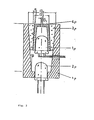
- the optical receiving part which detects at least two angular ranges separately from one another, preferably has a structure which corresponds in principle to the embodiment shown in FIG. 3.
- the device shown in FIG. 3 is characterized by a housing 5p, in the bottom surface of which a light detector 2p is provided centrally, and the inner surface of which, as seen from the light detector 2p, widens conically outwards, one concentrically X on the open side of the housing 5p of the conical surface provided annular glass body 3p, which consists of glass or another translucent material and the inner surface of which, as seen from the light detector 2p, narrows conically outwards, a radiation-impermeable or radiation-impermeable coated sleeve 4p arranged concentrically in the glass body 3p, which at its outward end extends to is closed to a central opening, and a light detector 1p provided concentrically in the sleeve 4p and in the optical axis of the arrangement, the diameter D2 of the central opening of the
- the inner surface of the housing 5p or the outer surface of the glass body 3p and / or the outer surface of the sleeve 4p or the inner surface of the glass body 3p can also advantageously be of parabolic curvature in cross section.
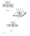
- FIG. 4 shows a further embodiment of the device according to the invention, in which the optical receiving part is designed flat.
- FIG. 4 a shows a sandwich-like arrangement of four layers, of which the bottom layer is a photosensitive layer; layers 2, 3 and 4 can either be light-sensitive or only have a mask function, depending on whether measurements are to be carried out using a two-signal method, a three-signal method or a multi-signal method.
- the variant of the optical receiving part shown in Fig.4a is preferably designed so that the bottom layer is light-sensitive, the second layer 2 above is radiation-opaque and has a central opening in the optical axis with the diameter D1, the third layer 3 above is light-sensitive and has a concentric central opening with the diameter D2, and the fourth layer above it has a central concentric opening with the diameter D3, which acts as an aperture mask.
- the resulting structure is shown schematically in FIG. 4b.
- an uppermost layer 5 made of an opaque material is provided, which has an annular opening with the diameters D2 and D3 and a central opening with the diameter D1 and acts as a mask for the layers 6 and 7 underneath .
- the layer provided under the uppermost layer 5 is light-sensitive and has a central concentric opening, the diameter of which lies between D1 and D2; there is also a light-sensitive layer 7 below it. This arrangement is particularly suitable for the two-signal process.
- the diameters D2 and D3 are selected in the cases of the devices of FIGS. 4a and 4c so that the intended range of scattering angles is detected.
- the devices of FIGS. 4a and 4c Compared to the embodiment of the optical receiving part shown in FIG. 3, the devices of FIGS. 4a and 4c have the advantage of a considerably smaller installation depth; however, these flat receiving parts cannot be constructed using commercially available components.
- the electrical or electronic part of the device according to the invention can be constructed from commercially available components.
- the part that is provided for the intensity control of the light source can, if necessary, be a controller with a special form of the control characteristic, since, for example, laser diodes are known to have a strongly non-linear current-intensity characteristic.
- the signal processing can be carried out both digitally and analogously.
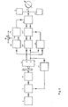
- FIG. 5 shows a basic circuit diagram of the electrical part of a device according to the invention with digital signal processing.
- the arrangement comprises a power supply 8, a control amplifier 9 for the light source, a light source 10 and various light detectors 12 which detect the light transmitted or scattered by the sample 11 and deliver corresponding measurement signals.
- a power supply 8 for the light source
- a light source 10 for the light source
- various light detectors 12 which detect the light transmitted or scattered by the sample 11 and deliver corresponding measurement signals.
- only two light detectors 12 are provided, from whose measurement signals in connection with a reference signal up to a maximum of five signal quantities (two absolute and three relative) can be derived.
- the generation of the relative signal quantities can take place before or after the conversion of the measurement signals into digital signals.
- the measurement signals of the light detectors 12 are amplified by assigned signal amplifiers 13 to 15 and passed via analog-digital converters 22 to a measurement value processing part 1, which can consist of a microprocessor, a microcomputer or another computer.
- a measurement value processing part 1 can consist of a microprocessor, a microcomputer or another computer.
- One or more differential amplifiers 16 or the like provide the relative intensities.
- the measured value processing part generates on the basis of predetermined functions or programs from the measured signal sequence signals that control the signal output, corrects the measured signals by comparison with entered constants and / or in another way, for example by forming differences, forming quotients, addition or subtraction, and also generates the required control variable, which then, for example reaches the control amplifier 9 via the DIA converter 21.
- the measured value processing part 17 may also be designed such that it detects and indicates rising or falling tendencies of the measurement signal or the output signal; the measured value processing part preferably also generates acoustic and / or optical signals with adjustable upper and / or lower limit values, for example warning signals, by means of suitable peripherals.
- the device can also be designed so that it is compatible with other data processing devices and can be connected to other data processing devices.
- the result is output via a display device 18, for example a digital voltmeter, the device further comprises an output device 19 which represents a measured value printer, a recorder or a similar registering and / or indicating instrument and is connected to the measured value processing part 17 via a DIA converter 23.
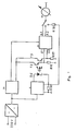
- FIG. 6 shows a block diagram of an embodiment of the electrical part according to the invention, in which the signal processing is carried out analogously.
- the circuit comprises like the circuit shown in FIG. 5 a power supply 8, a control amplifier 9 for the light source, a light source 10 and two light detectors 12 which detect the central beam or the scattered radiation coming from the sample 11.
- the circuit shown in FIG. 6 is designed for the two-signal method; In analog signal processing, methods based on the detection of three or more signals quickly lead to very extensive only two light detectors 12.
- the amplifier 23 ' is controlled by the ratio of the two measured values a / b via the quotient 25 and the amplifier 24 by the difference between the measurement signal a amplified by the amplifier 13 and the voltage which can be set at the resistor R and which is formed by a differential amplifier 16 .
- the measurement signal is correspondingly corrected by the circuit shown in FIG. 6 by amplifier 23 'and absolutely by amplifier 24; the resulting signal is displayed on the display device 18.
- the absolute intensity of the signal b can also be used via a control amplifier 27 to stabilize the intensity of the light source 10.
- the circuit of Figure 6 also includes a limit transmitter 28 which signals an upper and / or lower limit of the signal; (For example, it consists of two Schmitt triggers). The rising or falling tendency of the signal can be derived from the integrator 22 '.
- the circuit also includes an output device 19, i.e. for example a registering and possibly also indicating measuring instrument, e.g. a printer or a writer.
- the circuit of FIG. 6 can also be designed such that it is compatible and can be connected to other, possibly independent data processing devices or systems.
- circuits shown in Figs. 5 and 6 can also be designed so that with the help of the resulting signals, which are displayed by the display device 18 or registered by the output device 19, independent devices such as infusion devices and in particular devices for insulin dosing can optionally also be implantable, can be controlled.
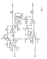
- FIG. 7 shows the basic circuit diagram of a technical embodiment of the device according to the invention, which is based on analog signal processing.
- all functions of the circuit of FIG. 6 are contained with the exception of the control amplifier 27, the limit value transmitter 28 and the output device 19.
- the functions are partially simplified or summarized, the measuring amplifier 30, which is explained in more detail in FIG. 8, the functions of the signal amplifier 13, the integrator 22 ', the amplifiers 23 and 24, the quotient 25 and the differential amplifier 16 of FIG 6 takes over.
- the power supply is based on the mains voltage (e.g. 220 V), which is initially converted into several, for example four, low voltages.
- An alternative power supply from batteries can be provided.
- the circuit has a power supply 29, which supplies the measuring amplifier 30 with a stabilized voltage, for example ⁇ 6 V.
- the two light detectors T2 and T3 are separately supplied by the power supply 29 with a highly stabilized voltage, for example +30 V.
- Resistors R16 and R17 are the signal resistances of light detectors T2 and T3.
- the CW laser diode D5 as a light source is supplied by the power supply with an electronically controlled, also highly stabilized voltage, the power supply being designed in particular in such a way that it also keeps voltage peaks of the mains voltage away from the diode.
- the current of the laser diode D5, which flows through the bypass resistor R18, can, if necessary, be displayed and monitored by the display device 18 with the aid of the series resistor R19.
- the measuring amplifier 30 works both as a differential amplifier and as a single amplifier, as explained in more detail below.
- the measuring amplifier 30 receives the corresponding signals from the light detectors T2 and T3 at its inputs E1 and E2. It has the outputs A1 and A2, which can be connected to the display device 18.
- the measuring amplifier 30 is shown schematically in detail. It forms the difference between the input signals from the signals arriving at inputs E1 and E2 via 1C1 and 1C2 using resistor R11. This difference is sent to output A2 via 1C4 and R15.
- the input signal arriving at E1 is also directly amplified by 1C1 and 1C3 and led to output A1 via R8.
- the gain of the signal channel for the differential signal i.e. the branch E2-IC2-IC4-R15, is regulated depending on the voltage at E1.
- the effectiveness of this control is determined by the resistors R9 and R14 and by the potentiometer P2, which determines the operating point of the operational amplifier 1C4.
- IC5 the voltage at the output of 1C3 is converted via the transistor T1, the diode D4 and the resistor R14 into a control current for the operational amplifier 1C4, whose gain can be regulated.
- the potentiometer P1 is used to set the setpoint for this control, which can be used to set a blood circulation correction on the earlobe, for example, when determining transcutaneous blood glucose.
- the maximum amplification in the signal branch is at least 10,000; an amplification of approximately 1000 is sufficient for the amplification of the branch El-A1.
- this factor is naturally also dependent on the sensitivity of the display instrument.
- the operating points of the operational amplifiers are determined by the following resistances, whereby these also determine the gain: for IC 1 of RI and R2, for IC 3 of R5, R6 and R7, for IC 2 of R10 and R12, for IC 4 besides P 2 also of R13.
- the usual offset zero potentiometers and capacitors for frequency compensation are not shown in the figure.
- the capacitors C1 and C4 serve to reduce the input interference voltages.
- the capacitors C2, C3 and C5 reduce the tendency of the amplifier to oscillate and at the same time serve to integrate the respective signal.
- FIG. 9 shows a device according to the invention for transcutaneous blood glucose determination in vivo on the earlobe, FIG. 9a showing the basic structure of the device and FIG. 9b correspondingly realizing a device to be worn on the body.
- the measurement setup is shown with solid lines; the dashed lines correspond to decorative elements.
- the device is designed as an ear clip, the laser diode D being provided in a cooling block K, which, however, is not absolutely necessary.
- the device also has a deflecting mirror U, which deflects the light emitted by the laser diode by approximately 90 °, so that it passes through the earlobe inserted into the ear clip; the optical receiving part E receives the laser light passing through or scattered through the earlobe, up to 4 or more signals being able to be detected separately from one another.
- the optical receiving part E is in the sandwich technology explained above or approximately in the form of the light pipe arrangement shown in FIG. 3 (cf. Light-pipe cone, in: DE Williamson, Cone Channel Condensor Optics, J. Opt. Soc. Amer.
- the optical receiving part E and the part of the device with the light source also have corresponding electrical supply lines or connecting lines to the current source and, if appropriate, to the signal processing device.
- the optical part is provided in a U-shaped carrier T, which has a resilient joint G in the base area, between the side parts of which an earlobe can be inserted.
- the external design of the device according to the invention shown in FIG. 9a can be chosen freely and is only determined by design considerations, so that it can be adapted to the individual taste of the wearer of the device.
- FIG. 9b The design of the device, indicated by dashed lines in FIG. 9a, is shown in FIG. 9b using a photograph of a specific embodiment. Similar to a conventional ear clip, the device is attached to the earlobe by a simple folding mechanism, the device preferably being made as light and small as possible.
- the power supply for the light source and the signal processing device are preferably provided independently of the ear clip-type actual measuring device and for example at a suitable location, e.g. carried in a bag or under clothing.
- Parts of the device according to the invention, e.g. the output device 19 or the display device 18 can also be designed, for example, in the form of a wristwatch or wristwatch-like device or, for example, a necklace-like device similar to a shoulder clock.
- a paper sample with a thickness such that the resulting mean intensity is equal to that of a biological sample leads to a value for the constant a of 0.19 and for the constant b of 1.15.
- the constants a and b result from an easily feasible curve fitting with pairs of values of the above-mentioned measured variables when measuring several intensities.
- the constants d and e must be determined once for each sample; Surprisingly, however, it has been found that they differ only slightly from sample to sample.
- the measurement correction when measuring biological samples for example with regard to the correction due to changing blood flow to the earlobe must take into account that the effective sample thickness x changes. It can therefore not be carried out simply by forming a ratio, as is possible, for example, with conventional optical two-beam methods.
- the ratio formation provides independence from the absolute intensity, but does not compensate for variable sample thickness.
- the correction function for example to correct different blood flow, must generally have an exponential form.
- the device advantageously has a temperature sensor for measuring the skin temperature at or near the measuring point, the signal of which is used to correct the measuring signals in the signal processing device.
- the measuring device is unchanged at a certain measuring point in all measurements or can be attached in a reproducible manner.
- Such a definition is particularly easy for female users of the ear clip shown in FIG. 9 who have pierced earlobes for jewelry purposes if the measuring device is inserted into the hole in the earlobe.
- the device according to the principle of FIG. 9 therefore advantageously has a corresponding mandrel for such applications, which is inserted through the hole in the earlobe.
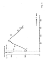
- FIG. 10 shows experimental results of a continuous transcutaneous blood glucose measurement carried out with a device according to the invention, a device similar to that of FIG. 9 being used.
- the measurements were carried out on a healthy test subject who, at the start of the experiment, used oral 400 ml of Dextro OG-T to generate a glucose load. were administered.
- Dextro OG-T. solution for oral glucose exposure corresponds to a physiological amount of 100 g anhydrous Glucose.
- 400 ml of juice contain 17 g of anhydrous glucose, 13 g of maltose, 11 g of maltotriose and 53 g of higher oligosaccharides. After hydrolysis in the intestinal tract, this mixture corresponds to the amount of glucose specified above (BM Toleranz-Test, Boehringer Mannheim GmbH, 6800 Mannheim 31).
- the device in the form of an ear clip was attached to the subject's earlobe.
- the device worked according to the two-signal method, with the absolute intensity of the central beam being used for correction.
- the resulting difference signal of the two measurement signals was generated by the signal processing device and recorded with a recorder.
- the method according to the invention and the device according to the invention are particularly suitable due to their underlying technical concept for miniaturization, which can go by orders of magnitude more than the embodiment shown in FIG. 9, micro-miniaturization and consequently also the possibilities of designing implantable devices. are already technically realistic today.
- the method according to the invention and the device according to the invention are not limited to the quantitative determination of glucose in aqueous and, in particular, biological systems, since with a suitable selection of the scattering angle ranges, other dissolved low-molecular and also high-molecular substances can be determined quantitatively in simple and composite systems in principle in the same way .
- the device according to the invention can also be modified to a very large extent within the framework of the inventive concept on the basis of the general technical concept on which it is based.
- the method according to the invention and the device according to the invention thus represent a completely new alternative to previous methods and devices for determining blood glucose as well as for the transcutaneous determination of other blood components and blood values (erythrocyte number, Hb value and the like).
Landscapes
- Health & Medical Sciences (AREA)
- Life Sciences & Earth Sciences (AREA)
- Physics & Mathematics (AREA)
- General Health & Medical Sciences (AREA)
- Pathology (AREA)
- Biophysics (AREA)
- Medical Informatics (AREA)
- Veterinary Medicine (AREA)
- Public Health (AREA)
- Animal Behavior & Ethology (AREA)
- Surgery (AREA)
- Optics & Photonics (AREA)
- Molecular Biology (AREA)
- Engineering & Computer Science (AREA)
- Biomedical Technology (AREA)
- Heart & Thoracic Surgery (AREA)
- Biochemistry (AREA)
- Chemical & Material Sciences (AREA)
- Spectroscopy & Molecular Physics (AREA)
- Analytical Chemistry (AREA)
- Immunology (AREA)
- General Physics & Mathematics (AREA)
- Emergency Medicine (AREA)
- Investigating Or Analysing Materials By Optical Means (AREA)
- Investigating Or Analysing Biological Materials (AREA)
- Measurement Of The Respiration, Hearing Ability, Form, And Blood Characteristics Of Living Organisms (AREA)
Claims (34)
et
et
Priority Applications (3)
| Application Number | Priority Date | Filing Date | Title |
|---|---|---|---|
| DE8181107264T DE3176091D1 (en) | 1981-09-15 | 1981-09-15 | Method and device for the quantitative determination of dissolved substances in single- or multicomponent systems of laser light scattering |
| EP81107264A EP0074428B1 (fr) | 1981-09-15 | 1981-09-15 | Procédé et dispositif pour la détermination quantitative de substances en solution dans des systèmes à un ou plusieurs composants par dispersion de lumière laser |
| AT81107264T ATE26485T1 (de) | 1981-09-15 | 1981-09-15 | Verfahren und vorrichtung zur quantitativen bestimmung geloester substanzen in ein- und mehrkomponentensystemen durch laserlichtstreuung. |
Applications Claiming Priority (1)
| Application Number | Priority Date | Filing Date | Title |
|---|---|---|---|
| EP81107264A EP0074428B1 (fr) | 1981-09-15 | 1981-09-15 | Procédé et dispositif pour la détermination quantitative de substances en solution dans des systèmes à un ou plusieurs composants par dispersion de lumière laser |
Publications (2)
| Publication Number | Publication Date |
|---|---|
| EP0074428A1 EP0074428A1 (fr) | 1983-03-23 |
| EP0074428B1 true EP0074428B1 (fr) | 1987-04-08 |
Family
ID=8187912
Family Applications (1)
| Application Number | Title | Priority Date | Filing Date |
|---|---|---|---|
| EP81107264A Expired EP0074428B1 (fr) | 1981-09-15 | 1981-09-15 | Procédé et dispositif pour la détermination quantitative de substances en solution dans des systèmes à un ou plusieurs composants par dispersion de lumière laser |
Country Status (3)
| Country | Link |
|---|---|
| EP (1) | EP0074428B1 (fr) |
| AT (1) | ATE26485T1 (fr) |
| DE (1) | DE3176091D1 (fr) |
Cited By (26)
| Publication number | Priority date | Publication date | Assignee | Title |
|---|---|---|---|---|
| EP0160768A1 (fr) * | 1984-05-04 | 1985-11-13 | Kurabo Industries Ltd. | Dispositif spectrophotométrique pour la détermination, par voie non-invasive, de glucose dans les tissus vivants |
| US4657383A (en) * | 1983-10-31 | 1987-04-14 | Bellhouse Brian John | Optical assay method for stored human platelets |
| US4830510A (en) * | 1983-10-31 | 1989-05-16 | Bellhouse Brian John | Optical assay method for stored human platelets |
| EP0426358A1 (fr) * | 1989-10-28 | 1991-05-08 | Won Suck Yang | Méthode et appareil de mesure non invasive de la concentration d'une substance chimique dans le sang |
| WO1991015992A1 (fr) * | 1990-04-19 | 1991-10-31 | Worcester Polytechnic Institute | Procede et appareil de mesure de la concentration de substances absorbantes |
| EP0456716A4 (en) * | 1989-01-19 | 1992-06-03 | Futrex, Inc. | Non-invasive measurement of blood glucose |
| US5204532A (en) * | 1989-01-19 | 1993-04-20 | Futrex, Inc. | Method for providing general calibration for near infrared instruments for measurement of blood glucose |
| US5218207A (en) * | 1989-01-19 | 1993-06-08 | Futrex, Inc. | Using led harmonic wavelengths for near-infrared quantitative |
| US5237178A (en) * | 1990-06-27 | 1993-08-17 | Rosenthal Robert D | Non-invasive near-infrared quantitative measurement instrument |
| US5324979A (en) * | 1990-09-26 | 1994-06-28 | Futrex, Inc. | Method and means for generating synthetic spectra allowing quantitative measurement in near infrared measuring instruments |
| DE4393335D2 (de) * | 1992-11-09 | 1994-07-21 | Boehringer Mannheim Gmbh | Verfahren und Vorrichtung zur Analyse von Glucose in einer biologischen Matrix |
| US5574283A (en) * | 1990-06-27 | 1996-11-12 | Futrex, Inc. | Non-invasive near-infrared quantitative measurement instrument |
| GB2304187A (en) * | 1995-08-07 | 1997-03-12 | Dia Stron Ltd | Translucency measurement |
| US5638818A (en) * | 1991-03-21 | 1997-06-17 | Masimo Corporation | Low noise optical probe |
| US5692504A (en) * | 1993-11-04 | 1997-12-02 | Boehringer Mannheim Gmbh | Method and apparatus for the analysis of glucose in a biological matrix |
| US5710630A (en) * | 1994-05-05 | 1998-01-20 | Boehringer Mannheim Gmbh | Method and apparatus for determining glucose concentration in a biological sample |
| US6066847A (en) * | 1989-01-19 | 2000-05-23 | Futrex Inc. | Procedure for verifying the accuracy of non-invasive blood glucose measurement instruments |
| US6110522A (en) * | 1995-06-07 | 2000-08-29 | Masimo Laboratories | Blood glucose monitoring system |
| US6329139B1 (en) | 1995-04-25 | 2001-12-11 | Discovery Partners International | Automated sorting system for matrices with memory |
| US6541756B2 (en) | 1991-03-21 | 2003-04-01 | Masimo Corporation | Shielded optical probe having an electrical connector |
| US6627911B2 (en) | 1999-12-01 | 2003-09-30 | Fresenius Hemocare Gmbh | Method for determining a particle concentration and device for implementing the method |
| WO2003079899A1 (fr) * | 2002-03-27 | 2003-10-02 | MCC Gesellschaft für Diagnosesysteme in Medizin und Technik mbH & Co. KG | Dispositif et procede de mesure de constituants du sang |
| US7003337B2 (en) | 2002-04-26 | 2006-02-21 | Vivascan Corporation | Non-invasive substance concentration measurement using and optical bridge |
| DE19519051B4 (de) * | 1995-05-24 | 2007-05-03 | Diabetic Trust Ag | Verfahren und Vorrichtung zur polarimetrischen Bestimmung der Blutzuckerkonzentration |
| US8175666B2 (en) | 2002-04-26 | 2012-05-08 | Grove Instruments, Inc. | Three diode optical bridge system |
| US9560998B2 (en) | 2006-10-12 | 2017-02-07 | Masimo Corporation | System and method for monitoring the life of a physiological sensor |
Families Citing this family (9)
| Publication number | Priority date | Publication date | Assignee | Title |
|---|---|---|---|---|
| EP0576560B1 (fr) * | 1991-03-21 | 2000-05-03 | Masimo Corporation | Sonde optique de reduction du bruit |
| US6952603B2 (en) | 2001-03-16 | 2005-10-04 | Roche Diagnostics Operations, Inc. | Subcutaneous analyte sensor |
| US10188348B2 (en) | 2006-06-05 | 2019-01-29 | Masimo Corporation | Parameter upgrade system |
| US8571619B2 (en) | 2009-05-20 | 2013-10-29 | Masimo Corporation | Hemoglobin display and patient treatment |
| DE102010014775A1 (de) * | 2010-04-13 | 2011-10-13 | Vivantum Gmbh | Vorrichtung und Verfahren zur Bestimmen eines biologischen, chemischen und/oder physikalischen Parameters in lebendem biologischem Gewebe |
| DE102011119824B4 (de) | 2011-12-01 | 2013-07-04 | Fresenius Medical Care Deutschland Gmbh | Verfahren und Vorrichtung zur Bestimmung eines Blutbestandteils |
| US9795329B2 (en) * | 2014-01-10 | 2017-10-24 | Glucovista Inc. | Non-invasive device and method for measuring a substance concentration |
| US10987055B2 (en) | 2017-05-19 | 2021-04-27 | Glucovista Inc. | Substance concentration NIR monitoring apparatuses and methods |
| CN116831576A (zh) * | 2023-08-02 | 2023-10-03 | 桂林电子科技大学 | 一种新型偏振度无创血糖仪 |
Family Cites Families (7)
| Publication number | Priority date | Publication date | Assignee | Title |
|---|---|---|---|---|
| US3310680A (en) * | 1964-03-06 | 1967-03-21 | Hasegawa Toshitsune | Photosensitive concentration measuring apparatus for colloidal solutions |
| US3659946A (en) * | 1969-12-10 | 1972-05-02 | Shimadzu Corp | Automated light scattering photometer |
| US3786261A (en) * | 1971-10-12 | 1974-01-15 | Coulter Electronics | Optical scanning device |
| CH595113A5 (fr) * | 1976-03-18 | 1978-01-31 | Cerberus Ag | |
| GB1556029A (en) * | 1976-10-29 | 1979-11-14 | Standard Telephones Cables Ltd | Oil in water detection |
| US4118625A (en) * | 1977-05-02 | 1978-10-03 | Dynatech Laboratories Incorporated | Nephelometer having pulsed energy source |
| DE2944113A1 (de) * | 1979-10-31 | 1981-05-14 | Arno Dipl.-Phys. Dr. 7900 Ulm Müller | Verfahren und vorrichtung zur quantitativen absolutbestimmung optisch aktiver substanzen |
-
1981
- 1981-09-15 DE DE8181107264T patent/DE3176091D1/de not_active Expired
- 1981-09-15 AT AT81107264T patent/ATE26485T1/de not_active IP Right Cessation
- 1981-09-15 EP EP81107264A patent/EP0074428B1/fr not_active Expired
Cited By (32)
| Publication number | Priority date | Publication date | Assignee | Title |
|---|---|---|---|---|
| US4657383A (en) * | 1983-10-31 | 1987-04-14 | Bellhouse Brian John | Optical assay method for stored human platelets |
| US4682887A (en) * | 1983-10-31 | 1987-07-28 | Brian J. Bellhouse | Optical assay for stored human platelets |
| US4830510A (en) * | 1983-10-31 | 1989-05-16 | Bellhouse Brian John | Optical assay method for stored human platelets |
| EP0160768A1 (fr) * | 1984-05-04 | 1985-11-13 | Kurabo Industries Ltd. | Dispositif spectrophotométrique pour la détermination, par voie non-invasive, de glucose dans les tissus vivants |
| US5218207A (en) * | 1989-01-19 | 1993-06-08 | Futrex, Inc. | Using led harmonic wavelengths for near-infrared quantitative |
| EP0456716A4 (en) * | 1989-01-19 | 1992-06-03 | Futrex, Inc. | Non-invasive measurement of blood glucose |
| US5204532A (en) * | 1989-01-19 | 1993-04-20 | Futrex, Inc. | Method for providing general calibration for near infrared instruments for measurement of blood glucose |
| US6066847A (en) * | 1989-01-19 | 2000-05-23 | Futrex Inc. | Procedure for verifying the accuracy of non-invasive blood glucose measurement instruments |
| US5576544A (en) * | 1989-01-19 | 1996-11-19 | Futrex, Inc. | Method for providing general calibration for near infrared instruments for measurement of blood glucose |
| JPH03146032A (ja) * | 1989-10-28 | 1991-06-21 | Won S Yang | 生体を損なわない血糖濃度測定装置 |
| EP0426358A1 (fr) * | 1989-10-28 | 1991-05-08 | Won Suck Yang | Méthode et appareil de mesure non invasive de la concentration d'une substance chimique dans le sang |
| WO1991015992A1 (fr) * | 1990-04-19 | 1991-10-31 | Worcester Polytechnic Institute | Procede et appareil de mesure de la concentration de substances absorbantes |
| US5237178A (en) * | 1990-06-27 | 1993-08-17 | Rosenthal Robert D | Non-invasive near-infrared quantitative measurement instrument |
| US5574283A (en) * | 1990-06-27 | 1996-11-12 | Futrex, Inc. | Non-invasive near-infrared quantitative measurement instrument |
| US5324979A (en) * | 1990-09-26 | 1994-06-28 | Futrex, Inc. | Method and means for generating synthetic spectra allowing quantitative measurement in near infrared measuring instruments |
| US5638818A (en) * | 1991-03-21 | 1997-06-17 | Masimo Corporation | Low noise optical probe |
| US6088607A (en) * | 1991-03-21 | 2000-07-11 | Masimo Corporation | Low noise optical probe |
| US7483730B2 (en) | 1991-03-21 | 2009-01-27 | Masimo Corporation | Low-noise optical probes for reducing ambient noise |
| US6541756B2 (en) | 1991-03-21 | 2003-04-01 | Masimo Corporation | Shielded optical probe having an electrical connector |
| DE4393335D2 (de) * | 1992-11-09 | 1994-07-21 | Boehringer Mannheim Gmbh | Verfahren und Vorrichtung zur Analyse von Glucose in einer biologischen Matrix |
| US5692504A (en) * | 1993-11-04 | 1997-12-02 | Boehringer Mannheim Gmbh | Method and apparatus for the analysis of glucose in a biological matrix |
| US5710630A (en) * | 1994-05-05 | 1998-01-20 | Boehringer Mannheim Gmbh | Method and apparatus for determining glucose concentration in a biological sample |
| US6329139B1 (en) | 1995-04-25 | 2001-12-11 | Discovery Partners International | Automated sorting system for matrices with memory |
| DE19519051B4 (de) * | 1995-05-24 | 2007-05-03 | Diabetic Trust Ag | Verfahren und Vorrichtung zur polarimetrischen Bestimmung der Blutzuckerkonzentration |
| US6110522A (en) * | 1995-06-07 | 2000-08-29 | Masimo Laboratories | Blood glucose monitoring system |
| GB2304187A (en) * | 1995-08-07 | 1997-03-12 | Dia Stron Ltd | Translucency measurement |
| GB2304187B (en) * | 1995-08-07 | 1998-12-30 | Dia Stron Ltd | Translucency measurement |
| US6627911B2 (en) | 1999-12-01 | 2003-09-30 | Fresenius Hemocare Gmbh | Method for determining a particle concentration and device for implementing the method |
| WO2003079899A1 (fr) * | 2002-03-27 | 2003-10-02 | MCC Gesellschaft für Diagnosesysteme in Medizin und Technik mbH & Co. KG | Dispositif et procede de mesure de constituants du sang |
| US7003337B2 (en) | 2002-04-26 | 2006-02-21 | Vivascan Corporation | Non-invasive substance concentration measurement using and optical bridge |
| US8175666B2 (en) | 2002-04-26 | 2012-05-08 | Grove Instruments, Inc. | Three diode optical bridge system |
| US9560998B2 (en) | 2006-10-12 | 2017-02-07 | Masimo Corporation | System and method for monitoring the life of a physiological sensor |
Also Published As
| Publication number | Publication date |
|---|---|
| DE3176091D1 (en) | 1987-05-14 |
| EP0074428A1 (fr) | 1983-03-23 |
| ATE26485T1 (de) | 1987-04-15 |
Similar Documents
| Publication | Publication Date | Title |
|---|---|---|
| EP0074428B1 (fr) | Procédé et dispositif pour la détermination quantitative de substances en solution dans des systèmes à un ou plusieurs composants par dispersion de lumière laser | |
| DE69032535T2 (de) | Verfahren und Vorrichtung zur Bestimmung der Ähnlichkeit eines biologischen Analyts, ausgehend von einem aus bekannten biologischen Fluiden hergestellten Modell | |
| EP1518495B1 (fr) | Procédé et dispositif de surveillance continue de la concentration d'un analyte | |
| DE69032126T2 (de) | Nicht-invasive messung der glukose im blut | |
| DE19952215C2 (de) | Testelement-Analysesystem | |
| DE69721732T2 (de) | Vorrichtung zur multispektralen analyse bei der nichtinvasiven nir-spektroskopie | |
| DE69418546T2 (de) | Vorrichtung und Verfahren zur Messung der Konzentration von Glukose mittels Lichtstreuung | |
| DE69837425T2 (de) | Verfahren und Vorrichtung zur nichtinvasiven photoakustischen Messung von Blutglukose | |
| EP2046190B1 (fr) | Mesure de la concentration en glucose dans le sang pulsatif | |
| EP0659055B1 (fr) | Procede et dispositif d'analyse de glucose dans une matrice biologique | |
| EP3051272B1 (fr) | Procédé et analyseur automatique de détermination de lipides et d'autres substances interférentes dans des échantillons de liquide corporel | |
| DE69232482T2 (de) | Gasanalysegerät | |
| DE2944113C2 (fr) | ||
| DE69636403T2 (de) | Spektrometrie und optisches Messverfahren und Vorrichtung | |
| EP0774658A2 (fr) | Procédé et dispositif de détermination de données analytiques concernant l'intérieur d'un milieu diffusant | |
| DE2428884A1 (de) | Absorptionsspektrographisches analyseverfahren und einrichtung zu seiner durchfuehrung | |
| DD300132A5 (de) | Einrichtung und verfahren zum nachweisen und messen der konzentration von substanzen in einer probe durch optoakustische spektroskopie | |
| DE602004001075T2 (de) | Gerät zur nichtinvasiven Konzentrationsmessung einer Blutkomponente | |
| DE2431323A1 (de) | Verfahren zur analyse und zur bestimmung der konzentration von komponenten eines substanzgemisches und vorrichtung zur durchfuehrung des verfahrens | |
| DE3814718A1 (de) | Messeinrichtung zum analysieren mittels infrarotstrahlung | |
| DE602004001794T2 (de) | Verfahren und Vorrichtung zur in vitro oder in vivo Messung der Konzentration einer Substanz | |
| CH640350A5 (en) | Instrument for the quantitative determination of optically active substances | |
| DE69315015T2 (de) | Spektrophotometrische Methode und Spektrophotometer zur Druchführung der Methode | |
| DE2319465A1 (de) | Analysesystem | |
| DE4314835A1 (de) | Verfahren und Vorrichtung zur Analyse von Glucose in einer biologischen Matrix |
Legal Events
| Date | Code | Title | Description |
|---|---|---|---|
| PUAI | Public reference made under article 153(3) epc to a published international application that has entered the european phase |
Free format text: ORIGINAL CODE: 0009012 |
|
| AK | Designated contracting states |
Designated state(s): AT CH DE FR GB LI NL |
|
| 17P | Request for examination filed |
Effective date: 19830915 |
|
| GRAA | (expected) grant |
Free format text: ORIGINAL CODE: 0009210 |
|
| AK | Designated contracting states |
Kind code of ref document: B1 Designated state(s): AT CH DE FR GB LI NL |
|
| REF | Corresponds to: |
Ref document number: 26485 Country of ref document: AT Date of ref document: 19870415 Kind code of ref document: T |
|
| REF | Corresponds to: |
Ref document number: 3176091 Country of ref document: DE Date of ref document: 19870514 |
|
| ET | Fr: translation filed | ||
| PLBE | No opposition filed within time limit |
Free format text: ORIGINAL CODE: 0009261 |
|
| STAA | Information on the status of an ep patent application or granted ep patent |
Free format text: STATUS: NO OPPOSITION FILED WITHIN TIME LIMIT |
|
| 26N | No opposition filed | ||
| REG | Reference to a national code |
Ref country code: CH Ref legal event code: PUE Owner name: BANG & OLUFSEN TECHNOLOGY A/S |
|
| REG | Reference to a national code |
Ref country code: GB Ref legal event code: 732E |
|
| REG | Reference to a national code |
Ref country code: FR Ref legal event code: TP |
|
| NLS | Nl: assignments of ep-patents |
Owner name: BANG & OLUFSEN TECHNOLOGY A/S TE STRUER, DENEMARKE |
|
| PGFP | Annual fee paid to national office [announced via postgrant information from national office to epo] |
Ref country code: DE Payment date: 20000710 Year of fee payment: 20 |
|
| PGFP | Annual fee paid to national office [announced via postgrant information from national office to epo] |
Ref country code: NL Payment date: 20000711 Year of fee payment: 20 |
|
| PGFP | Annual fee paid to national office [announced via postgrant information from national office to epo] |
Ref country code: FR Payment date: 20000712 Year of fee payment: 20 |
|
| PGFP | Annual fee paid to national office [announced via postgrant information from national office to epo] |
Ref country code: GB Payment date: 20000904 Year of fee payment: 20 |
|
| PGFP | Annual fee paid to national office [announced via postgrant information from national office to epo] |
Ref country code: AT Payment date: 20000928 Year of fee payment: 20 |
|
| PGFP | Annual fee paid to national office [announced via postgrant information from national office to epo] |
Ref country code: CH Payment date: 20001204 Year of fee payment: 20 |
|
| PG25 | Lapsed in a contracting state [announced via postgrant information from national office to epo] |
Ref country code: LI Free format text: LAPSE BECAUSE OF EXPIRATION OF PROTECTION Effective date: 20010914 Ref country code: GB Free format text: LAPSE BECAUSE OF EXPIRATION OF PROTECTION Effective date: 20010914 Ref country code: CH Free format text: LAPSE BECAUSE OF EXPIRATION OF PROTECTION Effective date: 20010914 |
|
| PG25 | Lapsed in a contracting state [announced via postgrant information from national office to epo] |
Ref country code: NL Free format text: LAPSE BECAUSE OF EXPIRATION OF PROTECTION Effective date: 20010915 Ref country code: AT Free format text: LAPSE BECAUSE OF EXPIRATION OF PROTECTION Effective date: 20010915 |
|
| REG | Reference to a national code |
Ref country code: GB Ref legal event code: PE20 Effective date: 20010914 |
|
| REG | Reference to a national code |
Ref country code: CH Ref legal event code: PL |
|
| NLV7 | Nl: ceased due to reaching the maximum lifetime of a patent |
Effective date: 20010915 |