EP0074458A2 - Poussoir à galet - Google Patents
Poussoir à galet Download PDFInfo
- Publication number
- EP0074458A2 EP0074458A2 EP82101263A EP82101263A EP0074458A2 EP 0074458 A2 EP0074458 A2 EP 0074458A2 EP 82101263 A EP82101263 A EP 82101263A EP 82101263 A EP82101263 A EP 82101263A EP 0074458 A2 EP0074458 A2 EP 0074458A2
- Authority
- EP
- European Patent Office
- Prior art keywords
- roller
- bearing
- guide body
- axis
- axle
- Prior art date
- Legal status (The legal status is an assumption and is not a legal conclusion. Google has not performed a legal analysis and makes no representation as to the accuracy of the status listed.)
- Withdrawn
Links
- 229910000831 Steel Inorganic materials 0.000 claims description 3
- 239000010959 steel Substances 0.000 claims description 3
- 239000011796 hollow space material Substances 0.000 abstract 1
- 230000014759 maintenance of location Effects 0.000 abstract 1
- 238000002485 combustion reaction Methods 0.000 description 3
- 238000004519 manufacturing process Methods 0.000 description 3
- 239000007787 solid Substances 0.000 description 3
- 238000003466 welding Methods 0.000 description 3
- 238000010894 electron beam technology Methods 0.000 description 2
- 230000002093 peripheral effect Effects 0.000 description 2
- 238000005476 soldering Methods 0.000 description 2
- 238000003860 storage Methods 0.000 description 2
- 241000883965 Astrophytum myriostigma Species 0.000 description 1
- 241001326500 Barringtonia asiatica Species 0.000 description 1
- 238000010276 construction Methods 0.000 description 1
- 238000006073 displacement reaction Methods 0.000 description 1
- 238000005553 drilling Methods 0.000 description 1
- 235000018905 epimedium Nutrition 0.000 description 1
- 238000001125 extrusion Methods 0.000 description 1
- 238000003754 machining Methods 0.000 description 1
- 239000000463 material Substances 0.000 description 1
- 239000002184 metal Substances 0.000 description 1
- 238000000034 method Methods 0.000 description 1
- IHQKEDIOMGYHEB-UHFFFAOYSA-M sodium dimethylarsinate Chemical class [Na+].C[As](C)([O-])=O IHQKEDIOMGYHEB-UHFFFAOYSA-M 0.000 description 1
- 239000011343 solid material Substances 0.000 description 1
- 239000013585 weight reducing agent Substances 0.000 description 1
Images

Classifications
-
- F—MECHANICAL ENGINEERING; LIGHTING; HEATING; WEAPONS; BLASTING
- F01—MACHINES OR ENGINES IN GENERAL; ENGINE PLANTS IN GENERAL; STEAM ENGINES
- F01L—CYCLICALLY OPERATING VALVES FOR MACHINES OR ENGINES
- F01L1/00—Valve-gear or valve arrangements, e.g. lift-valve gear
- F01L1/12—Transmitting gear between valve drive and valve
- F01L1/14—Tappets; Push rods
-
- F—MECHANICAL ENGINEERING; LIGHTING; HEATING; WEAPONS; BLASTING
- F01—MACHINES OR ENGINES IN GENERAL; ENGINE PLANTS IN GENERAL; STEAM ENGINES
- F01L—CYCLICALLY OPERATING VALVES FOR MACHINES OR ENGINES
- F01L2305/00—Valve arrangements comprising rollers
Definitions
- the invention relates to a roller tappet with a guide body to which an axle is attached and which has bearing portions between the axle ends holding a recess into which a roller rotatably mounted on the axle engages.
- Such tappets are used in the valve train of internal combustion engines, piston compressors and pumps.
- the recesses of the guide body of known roller tappets receiving the axle ends were designed as bores, which not only had to be drilled, but also had to be ground or honed in order to avoid play on the roller axis and to precisely determine their position relative to the circumference of the guide body.
- the production was therefore relatively complex, and in addition the known roller tappets of the type described are also relatively heavy, since they have a solid guide body.
- the invention was based on the object of improving known roller tappets of the type mentioned in such a way that they can be produced more cheaply than hitherto.
- roller tappet has a lower weight than a comparable known roller tappet, which meets the requirement to use components with the smallest possible mass in the valve train of internal combustion engines, in order to increase the possible maximum speed of the units.
- the lower weight of the roller tappet according to the invention is due to the fact that the bearing parts of the guide body have a lower height than in known constructions - they no longer have to overlap the axle ends.
- a further reduction in weight is achieved in that the guide body is formed as a deep-drawn sheet steel part, an optimal weight reduction then being achieved by making the guide body approximately pot-shaped and designing it so that it has a cavity that is open towards the roller in which the role is partially immersed.
- a defined support of the roller axis can also be achieved, since the bearing troughs do not have to have a circular cross section, but can have a profile in the form of a prism or a so-called bishop's cap, so that the roller axis in each bearing trough in any case along two lines lies on; in comparison to the prior art, this results in a defined support of the roller axis in the bearing troughs.
- the guide body can consist of solid material or can be designed as a hollow body; the same applies to the roller axis.
- Figure 1 shows a solid guide body (10), in the bottom (12) of a pan (14) for the push rod of the valve control e.g. an internal combustion engine.
- a groove (18) is provided in its peripheral surface (16) for the engagement of an anti-twist device (not shown).
- Two bearing jaws (20) are integrally formed on the guide body 10, between which there is a transverse slot (22) and into each of which a bearing trough (24) has been incorporated at the top.
- An axis (30) is inserted into these storage troughs sets, on which a roller (34) is rotatably mounted by means of a bearing bush (32).
- This roller engages in the transverse slot (22) of the guide body (10), but without touching its boundaries. Since, during operation, the roller tappet lies between parts of a valve control, not shown, namely between a camshaft and an associated tappet rod or an associated lever, the forces generated by the valve springs of the unit ensure that the axis (30) is pressed into the bearing recesses (24) becomes.
- axle (30) lying in the bearing troughs (24) it is therefore sufficient to secure the ends of the axle (30) lying in the bearing troughs (24) by caulking the material of the bearing jaws (20) in the axial direction and upwards.
- the axis (30) can also be secured by soldering or by electron beam welding.
- FIG. 1a shows the profile of one of the bearing troughs (24), which corresponds almost to a semicircle with radius "r" around the center (40) of the laughing axis (30), the center (40), however, by the distance " a "lies above the upper edge of the bearing jaw (20). In this way it is ensured that the axis (30) can easily be inserted into the bearing troughs (24) from above.
- the center of the axle (40) can also lie slightly below the upper edge of the bearing jaw in order to achieve a kind of snapping of the bearing axle (30) into the bearing recesses or to facilitate caulking the bearing axle to fix it.
- FIG. 1b shows a particularly advantageous embodiment of a bearing recess (24 '), the profile of which is created by hitting two near-quarter circles with radius "r" around points (40') and (40 "), which are opposite the center of the axis ( 40) are slightly offset to the right or left and consequently have a distance "e” from one another.
- the centers of the circular arcs are in turn at a small distance "a” either above or below the upper edge of the bearing jaws (20) and are thus offset to the center of the axis (40) that the radii "r” overlap.
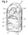
- the particularly advantageous roller tappet according to FIG. 2 has a guide body (10 ') which is deep-drawn from sheet steel and which has an upwardly opening cavity (22'), in the upper opening (23 ') of which the roller (34) engages.
- a window (18 ') is incorporated into the peripheral surface (16) for the purpose of preventing rotation.
- Pan (14) and bearing recesses (24) manufacturing the deep-drawing process' len so that it is a relatively inexpensive part.
- this embodiment brings with it great progress in terms of weight saving compared to the known roller tappets with a solid guide body.
- the same purpose is served by two flattened portions (36) that extend vertically to the roller axis, since this results in a reduction in the wall thickness of the guide body in the regions of the guide body adjacent to the broad sides of the cavity (22 ').
- the bearing troughs can also have a profile, as shown in FIG. 1b.
Landscapes
- Engineering & Computer Science (AREA)
- Mechanical Engineering (AREA)
- General Engineering & Computer Science (AREA)
- Valve-Gear Or Valve Arrangements (AREA)
Applications Claiming Priority (2)
| Application Number | Priority Date | Filing Date | Title |
|---|---|---|---|
| DE3136202 | 1981-09-12 | ||
| DE3136202 | 1981-09-12 |
Publications (2)
| Publication Number | Publication Date |
|---|---|
| EP0074458A2 true EP0074458A2 (fr) | 1983-03-23 |
| EP0074458A3 EP0074458A3 (fr) | 1984-04-11 |
Family
ID=6141472
Family Applications (1)
| Application Number | Title | Priority Date | Filing Date |
|---|---|---|---|
| EP82101263A Withdrawn EP0074458A3 (fr) | 1981-09-12 | 1982-02-19 | Poussoir à galet |
Country Status (1)
| Country | Link |
|---|---|
| EP (1) | EP0074458A3 (fr) |
Cited By (4)
| Publication number | Priority date | Publication date | Assignee | Title |
|---|---|---|---|---|
| DE19909418A1 (de) * | 1999-03-04 | 2000-09-07 | Mahle Ventiltrieb Gmbh | Rollenstößel |
| DE102006028348B3 (de) * | 2006-06-20 | 2007-10-31 | Siemens Ag | Rollenlagerungsvorrichtung |
| WO2015154757A1 (fr) * | 2014-04-07 | 2015-10-15 | Schaeffler Technologies AG & Co. KG | Élément de transmission de course |
| CN110344902A (zh) * | 2013-09-27 | 2019-10-18 | Skf公司 | 凸轮从动件、喷射泵和阀致动器及制造方法 |
Family Cites Families (4)
| Publication number | Priority date | Publication date | Assignee | Title |
|---|---|---|---|---|
| US1565223A (en) * | 1919-02-10 | 1925-12-08 | Packard Motor Car Co | Hydrocarbon motor |
| FR2088683A5 (fr) * | 1970-04-21 | 1972-01-07 | Meca Stephanoise Const | |
| US3822683A (en) * | 1972-12-11 | 1974-07-09 | Caterpillar Tractor Co | Roller bearing retaining clip |
| DE2712450C2 (de) * | 1977-03-22 | 1984-08-23 | Klöckner-Humboldt-Deutz AG, 5000 Köln | Pumpenkolbenantrieb für eine Kraftstoffeinspritzpumpe für Brennkraftmaschinen |
-
1982
- 1982-02-19 EP EP82101263A patent/EP0074458A3/fr not_active Withdrawn
Cited By (7)
| Publication number | Priority date | Publication date | Assignee | Title |
|---|---|---|---|---|
| DE19909418A1 (de) * | 1999-03-04 | 2000-09-07 | Mahle Ventiltrieb Gmbh | Rollenstößel |
| DE102006028348B3 (de) * | 2006-06-20 | 2007-10-31 | Siemens Ag | Rollenlagerungsvorrichtung |
| JP2009541671A (ja) * | 2006-06-20 | 2009-11-26 | コンチネンタル オートモーティヴ ゲゼルシャフト ミット ベシュレンクテル ハフツング | ローラ支承装置 |
| US8522739B2 (en) | 2006-06-20 | 2013-09-03 | Continental Automotive Gmbh | Roller seating device |
| CN110344902A (zh) * | 2013-09-27 | 2019-10-18 | Skf公司 | 凸轮从动件、喷射泵和阀致动器及制造方法 |
| CN110344902B (zh) * | 2013-09-27 | 2021-05-11 | Skf公司 | 凸轮从动件、喷射泵和阀致动器及制造方法 |
| WO2015154757A1 (fr) * | 2014-04-07 | 2015-10-15 | Schaeffler Technologies AG & Co. KG | Élément de transmission de course |
Also Published As
| Publication number | Publication date |
|---|---|
| EP0074458A3 (fr) | 1984-04-11 |
Similar Documents
| Publication | Publication Date | Title |
|---|---|---|
| DE4024446C2 (de) | Kaltgeformter Kipphebel | |
| DE19939515C2 (de) | Federbein für ein Kraftfahrzeug mit einer Lagerung für eine Schraubenfeder | |
| EP0382135B1 (fr) | Elément d'enraînement pour lève-glace à câble | |
| EP0339441A2 (fr) | Loqueteau à billes | |
| EP0187217A1 (fr) | Poussoir hydraulique pour moteur à combustion interne | |
| DE10134402A1 (de) | Radial dämpfendes Buchsengummilager | |
| DE3426607C2 (fr) | ||
| DE2533019C2 (de) | Vorrichtung zur ausrichtbaren Halterung eines Lagers an einer ebenen Tragfläche | |
| WO2004079164A1 (fr) | Basculeur d'un mecanisme de distribution d'un moteur a combustion interne | |
| DE102012100583C5 (de) | Einsatz für Zellkulturen | |
| DE3927218A1 (de) | Daempfungselement zur lagerung von im kraftstoffbehaelter angeordneten kraftstoffpumpen | |
| EP0074458A2 (fr) | Poussoir à galet | |
| DE3801802C2 (fr) | ||
| DE3218546A1 (de) | Waelzlagerung | |
| DE3508500C2 (de) | Befestigung eines Kolbens auf einer Kolbenstange, insbesondere für hydraulische Teleskop-Schwingungsdämpfer | |
| EP1260679A2 (fr) | Poussoir de moteur à combustion interne | |
| EP0622134B1 (fr) | Dispositif pour le graissage de pièces en forme de bandes ou de plaques | |
| DE69302735T2 (de) | Schiebegelenkverbindung | |
| DE19750206A1 (de) | Spanlos geformter Schlepphebel | |
| DE19648859C2 (de) | Selbstpumpendes hydropneumatisches Federbein mit innerer Niveauregelung | |
| DE3405173C2 (de) | Radaufhängung für Kraftfahrzeuge | |
| DE2226429A1 (de) | Sonnenblende mit einem schwenklager, insbesondere fuer fahrzeuge | |
| DE2702961C2 (fr) | ||
| DE8126623U1 (de) | Rollenstössel | |
| WO2018166547A1 (fr) | Écrou pour une vis à billes et procédé de fabrication d'un écrou |
Legal Events
| Date | Code | Title | Description |
|---|---|---|---|
| PUAI | Public reference made under article 153(3) epc to a published international application that has entered the european phase |
Free format text: ORIGINAL CODE: 0009012 |
|
| AK | Designated contracting states |
Designated state(s): AT BE CH DE FR GB IT LI NL SE |
|
| PUAL | Search report despatched |
Free format text: ORIGINAL CODE: 0009013 |
|
| AK | Designated contracting states |
Designated state(s): AT BE CH DE FR GB IT LI NL SE |
|
| STAA | Information on the status of an ep patent application or granted ep patent |
Free format text: STATUS: THE APPLICATION HAS BEEN WITHDRAWN |
|
| 18W | Application withdrawn |
Withdrawal date: 19840921 |
|
| RIN1 | Information on inventor provided before grant (corrected) |
Inventor name: KNIERIEM, MANFRED Inventor name: WIZEMANN, KURT |