EP0074485A2 - Amélioration aux lecteurs optiques de forme allongée - Google Patents
Amélioration aux lecteurs optiques de forme allongée Download PDFInfo
- Publication number
- EP0074485A2 EP0074485A2 EP82106940A EP82106940A EP0074485A2 EP 0074485 A2 EP0074485 A2 EP 0074485A2 EP 82106940 A EP82106940 A EP 82106940A EP 82106940 A EP82106940 A EP 82106940A EP 0074485 A2 EP0074485 A2 EP 0074485A2
- Authority
- EP
- European Patent Office
- Prior art keywords
- wand scanner
- data
- optical wand
- optical
- scanner according
- Prior art date
- Legal status (The legal status is an assumption and is not a legal conclusion. Google has not performed a legal analysis and makes no representation as to the accuracy of the status listed.)
- Withdrawn
Links
Images


Classifications
-
- G—PHYSICS
- G06—COMPUTING OR CALCULATING; COUNTING
- G06K—GRAPHICAL DATA READING; PRESENTATION OF DATA; RECORD CARRIERS; HANDLING RECORD CARRIERS
- G06K7/00—Methods or arrangements for sensing record carriers, e.g. for reading patterns
- G06K7/10—Methods or arrangements for sensing record carriers, e.g. for reading patterns by electromagnetic radiation, e.g. optical sensing; by corpuscular radiation
- G06K7/10544—Methods or arrangements for sensing record carriers, e.g. for reading patterns by electromagnetic radiation, e.g. optical sensing; by corpuscular radiation by scanning of the records by radiation in the optical part of the electromagnetic spectrum
- G06K7/10821—Methods or arrangements for sensing record carriers, e.g. for reading patterns by electromagnetic radiation, e.g. optical sensing; by corpuscular radiation by scanning of the records by radiation in the optical part of the electromagnetic spectrum further details of bar or optical code scanning devices
- G06K7/10881—Methods or arrangements for sensing record carriers, e.g. for reading patterns by electromagnetic radiation, e.g. optical sensing; by corpuscular radiation by scanning of the records by radiation in the optical part of the electromagnetic spectrum further details of bar or optical code scanning devices constructional details of hand-held scanners
Definitions
- the invention relates to an ontical wand scanner of improved type, particularly suitable for collecting data for several uses, in the shops and warehouses, by means of either the bar code reading or the optical characters recognizing (OCR).
- OCR optical characters recognizing
- optical wand scanners which are now used are substan tially of two types only, which respectively are working in the two following ways:
- microprocessors are relatively encumbering (typical size is about: cm. 22 x 12 x 8 and the weight is about 600/800 grammes) and it is indispensable that the operator works with both hands, the one for holding the microprocessor and the other one for operating the keyboard or. alternatively, the optical wand scanner.
- This working manner relates to the same purposes for which the microprocessor has been designed, that is the utilization by persons which sole purpose is the data input into the microprocessor.
- an optical wand scanner system as just described is to be utilized by the shopmen or by other operators, whose main purpose isn't the data collection but for instance taking the ware from the schel ves. bringing it on the bench, to do sums etc.it is essential that such persons have the hands free and are not impeded by complicated structures, such as the optical wand scanner connected to the portable microprocessor just described.
- a portable optical wand scanner (and not a microprocessor with keyboard) has been expressly designed. which is able to operating in an autonomous manner (namely without the need to be connected to something) and which structure comprises: a very small memory, the logic system for reading and discharging and the autonomous voltage supply..
- the data stored in the optical wand scanner must be periodically discharged towards means which are able to elaborate them and for this aim the portable opti cal wand scanner as conceived by this invention may be directly discharged into the computers today most utilized in commerce (micro and minicomputers; etc o ), provided that they utilize standard interfacing systems, the relevant control programme and suitable connectors.
- said an optical wand scanner permits to extend to the optical wand scanners the revolution which has been produced by the fountain pens with respect to the pens with the ink-stand. Also in that fact, indeed, the old system was suitable for sedentary and/or full time operators, while the new one was suitable to moving operators, which were requiring to be free and to use the pen sometimes. Like the fountain pen which sometimes requires to be filled in with ink, the considered optical wand scanner must be sometimes discharged of the data stored in it o However, it is completely autonomous for a very long time, similarly to the fountain peno
- the present optical wand scanner is also independent from the utilized standard bar code system, as it may be provided with different reading programs (proper to that par ticular standard system). It is evident that with this system one may also achieve to have an optical wand scanner which is able to read the O.C.R. codes.
- the processor may utilize the data for an automatic warehouse administration, for effecting statistics on the sales and so on.
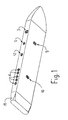
- An optical head 1 similar to that one produced by Hewlett-Packard and called HEDS-1000, is utilized for the reading.
- a head obviously known in the literature, comprises a light - emitting photodiode, a phototransistor sensiti- ves to the luminous intensity changes and a focusing lens. It is applied in the fore part of the optical wand scanner and suitably spaced apart from the end limit thereof.
- the wand scanner is slided at a suitable speed and inclination on a bar coded label, the light emitted by the photodiode hits the label and is reflected in a diffe rent manner by the white or black vertical bars.
- the signal interpretation and transcoding is depending on the used bar codifying system.
- the black bars width may be of two type. the one being the double of the other one, but with a non fixed size.
- the white bars act as separating bars only.
- the wand scanner according to this invention is a means which is particularly specialized to input data by an optical way. Nevertheless,in some cases it may be more suitable to effect a manual input by means of some keys, of the data logically connected with the following optical reading.
- the keys which are operated by subsequent or continuous pressure, allow the input of two numbers comprise frcm 0 to 9. In this case it is requested an integrated circuit (16) for the display control.
- the numbers are obtained from the program by adding a unit at a time in a proper memory register.
- the register content is transferred into the data memory together with the datum obtained by the optical way. This operation causes the register to be cleared and resets the outer indicators.
- the data which have been inputted into the portable unit, by optical and manual way, are stored sequentially in a RAM - memory 5.
- This system is designed for periodically transferring the stored data to the outer processors. This is done by introducing the end part of the optical wand scanner, in which a comb connector 6 is foresee and is normally protected by an extractable cover 15 in a plastic material, into a spring receptacle connected to the processor. When this mechanical connection has been done, the processor starts the data transferring which is controlled by the optical wand scanner and the processor control programs.
- the connection system at present time is a parallel interface of the Centronics - type.
- the processor is provided with serial gates only, it is possible to connect an outer appliance for the parallel-serial transforming downstream of the receptacle.
- the processor control program foresees the control of the received data and gives a message indicating correct or not correct transmission, with one or more totals, depending on the members of gates and simultaneous transmissions.
- the connected processor foresees until 5 simultaneously transmissions.
- control functions are performed by a microprocessor 7 and the control program of an EPROM-memory 8.
- MC 6805 micronrocessor of Motorola Co. which is realized on a single chip provided with 40 pins and can provide un to 8 K memory addresses.
- a 1 K bytes EPROM - memory is utilized, which is situated on a single chip provided with 28 pins.
- control program controls almost all the unit functions and particularly:
- the portable unit is operated by means of recessed spring keys having a short working path, which are:
- the voltage feeding is obtained by means of a rechargeable Nickel-Cadmium cell 14.
- the wand scanner For each introduction of the wand scanner into the receptacle for transferring the data on the connected processor, the wand scanner foresees a contemporary cell recharge. This function has already been foreseen on the present processor. This means in practice that the relevant optical wand scanners have an unlimited endurance and it will be never necessary to effect a separate cell recharge. In any case it is provided the possibility of detecting and signaling the discharged cell state and re charging the same cell through a separate recharging operation, in the case in which the processor does not provide itself to attend to this function.
- the technology to be selected defends on technical and economical factors. In any case it can be said that the result of this will be an optical wand scanner, which has been improved according to the present invention and is provided with size which are compatible with that ones of any traditional writing pen.
Landscapes
- Physics & Mathematics (AREA)
- Engineering & Computer Science (AREA)
- Electromagnetism (AREA)
- Artificial Intelligence (AREA)
- Toxicology (AREA)
- General Health & Medical Sciences (AREA)
- Health & Medical Sciences (AREA)
- Computer Vision & Pattern Recognition (AREA)
- General Physics & Mathematics (AREA)
- Theoretical Computer Science (AREA)
- Character Input (AREA)
- Character Discrimination (AREA)
- Cash Registers Or Receiving Machines (AREA)
Applications Claiming Priority (4)
| Application Number | Priority Date | Filing Date | Title |
|---|---|---|---|
| IT8141646A IT8141646A0 (it) | 1981-09-14 | 1981-09-14 | Perfezionamenti al sistema della penna ottica per la lettura dei codici a barre e ocr,particolarmente per la raccolta dei dati nei negozi e nei magazzini in genere. |
| IT4164681 | 1981-09-14 | ||
| IT45705/82A IT1158617B (it) | 1982-02-16 | 1982-02-16 | Penna ottica perfezionata |
| IT4570582 | 1982-02-16 |
Publications (2)
| Publication Number | Publication Date |
|---|---|
| EP0074485A2 true EP0074485A2 (fr) | 1983-03-23 |
| EP0074485A3 EP0074485A3 (fr) | 1984-03-28 |
Family
ID=26329138
Family Applications (1)
| Application Number | Title | Priority Date | Filing Date |
|---|---|---|---|
| EP82106940A Withdrawn EP0074485A3 (fr) | 1981-09-14 | 1982-07-31 | Amélioration aux lecteurs optiques de forme allongée |
Country Status (1)
| Country | Link |
|---|---|
| EP (1) | EP0074485A3 (fr) |
Cited By (6)
| Publication number | Priority date | Publication date | Assignee | Title |
|---|---|---|---|---|
| FR2561804A1 (fr) * | 1984-03-20 | 1985-09-27 | Loire Electro Region Pays | Procede et dispositif de lecture de code a barres |
| EP0194115A2 (fr) | 1985-02-28 | 1986-09-10 | Symbol Technologies, Inc. | Tête de lecture portable à diode laser |
| EP0217665A3 (fr) * | 1985-10-02 | 1989-08-23 | Videx, Inc. | Lecteur de code optique portatif et programmable |
| DE4124939A1 (de) * | 1991-07-27 | 1993-02-04 | Hugo Becker | Einrichtung fuer uebersetzungscomputer |
| WO1993003455A1 (fr) * | 1991-08-02 | 1993-02-18 | Intermec Corporation | Procede et appareil de lecture de symboles |
| DE4300317A1 (de) * | 1993-01-08 | 1994-07-14 | Thomson Brandt Gmbh | System zur Programmierung und/oder Eingabe von Informationen |
Family Cites Families (3)
| Publication number | Priority date | Publication date | Assignee | Title |
|---|---|---|---|---|
| US3826900A (en) * | 1972-10-13 | 1974-07-30 | Ncr | Cordless scanning probe |
| US4091270A (en) * | 1976-07-19 | 1978-05-23 | Hewlett-Packard Company | Electronic calculator with optical input means |
| US4101072A (en) * | 1976-10-21 | 1978-07-18 | The Singer Company | Data-gathering device for scanning data having a variable amplitude modulation and signal to noise ratio |
-
1982
- 1982-07-31 EP EP82106940A patent/EP0074485A3/fr not_active Withdrawn
Cited By (9)
| Publication number | Priority date | Publication date | Assignee | Title |
|---|---|---|---|---|
| FR2561804A1 (fr) * | 1984-03-20 | 1985-09-27 | Loire Electro Region Pays | Procede et dispositif de lecture de code a barres |
| EP0194115A2 (fr) | 1985-02-28 | 1986-09-10 | Symbol Technologies, Inc. | Tête de lecture portable à diode laser |
| EP0367299A2 (fr) | 1985-02-28 | 1990-05-09 | Symbol Technologies, Inc. | Tête de lecture portable à diode laser |
| EP0367300A3 (en) * | 1985-02-28 | 1990-05-23 | Symbol Technologies, Inc. | Portable laser diode scanning head |
| EP0217665A3 (fr) * | 1985-10-02 | 1989-08-23 | Videx, Inc. | Lecteur de code optique portatif et programmable |
| DE4124939A1 (de) * | 1991-07-27 | 1993-02-04 | Hugo Becker | Einrichtung fuer uebersetzungscomputer |
| WO1993003455A1 (fr) * | 1991-08-02 | 1993-02-18 | Intermec Corporation | Procede et appareil de lecture de symboles |
| US5548108A (en) * | 1991-08-02 | 1996-08-20 | Intermec Corporation | Method and apparatus for scanning symbols |
| DE4300317A1 (de) * | 1993-01-08 | 1994-07-14 | Thomson Brandt Gmbh | System zur Programmierung und/oder Eingabe von Informationen |
Also Published As
| Publication number | Publication date |
|---|---|
| EP0074485A3 (fr) | 1984-03-28 |
Similar Documents
| Publication | Publication Date | Title |
|---|---|---|
| US5468947A (en) | Pocket size data capture unit with processor and shell modules | |
| US4016542A (en) | Electronic notebook for use in data gathering, formatting and transmitting system | |
| CA1093694A (fr) | Systeme portatif roc (reconnaissance optique de caracteres) | |
| US4471218A (en) | Self-contained, portable data entry terminal | |
| US5672860A (en) | Integrated hand-held bar code processing device capable of automatic scan and data display | |
| US3942157A (en) | Data gathering formatting and transmitting system having portable data collecting device | |
| EP0083630B1 (fr) | Systeme commande par ordinateur, en temps reel, pour l'affichage des prix de vente | |
| US5123064A (en) | Hand-held data entry system and removable signature pad module therefor | |
| EP0067859B1 (fr) | Procede de collecte de donnees d'une etude de marche | |
| US4091270A (en) | Electronic calculator with optical input means | |
| US4423319A (en) | Communication link | |
| CA2200874C (fr) | Systeme de suivi de colis multiphase | |
| EP0798649A2 (fr) | Dispositif de terminal portable pour une carte à puce, compatible avec une pluralité d'applications | |
| TW357298B (en) | IC card portable terminal | |
| CA2395829A1 (fr) | Systeme de lecteur de la taille d'une chaussure | |
| EP0074485A2 (fr) | Amélioration aux lecteurs optiques de forme allongée | |
| GB2229559A (en) | Meter reading system | |
| KR101002703B1 (ko) | 바코드의 스캐너 기능을 갖는 휴대용 정보단말기 및 그를이용한 쓰레기봉투 관리시스템 | |
| EP0397376A3 (fr) | Interface pour système de balayage | |
| CN212873660U (zh) | 一种便携式带二代身份证和社保卡读卡功能的缴费设备 | |
| US20070205286A1 (en) | Portable multiple bar and other code display | |
| KR100446233B1 (ko) | 바코드 및 이차원 코드 판독 장치 | |
| CN208256038U (zh) | 一种新型pos机 | |
| JPH04149790A (ja) | ハンディ型端末装置 | |
| CN213958183U (zh) | 一种带识读二维码功能的pos键盘 |
Legal Events
| Date | Code | Title | Description |
|---|---|---|---|
| PUAI | Public reference made under article 153(3) epc to a published international application that has entered the european phase |
Free format text: ORIGINAL CODE: 0009012 |
|
| AK | Designated contracting states |
Designated state(s): AT BE CH DE FR GB IT LI NL SE |
|
| PUAL | Search report despatched |
Free format text: ORIGINAL CODE: 0009013 |
|
| AK | Designated contracting states |
Designated state(s): AT BE CH DE FR GB IT LI NL SE |
|
| 17P | Request for examination filed |
Effective date: 19840717 |
|
| STAA | Information on the status of an ep patent application or granted ep patent |
Free format text: STATUS: THE APPLICATION IS DEEMED TO BE WITHDRAWN |
|
| 18D | Application deemed to be withdrawn |
Effective date: 19860608 |