EP0074493B1 - Système de commande d'avion - Google Patents
Système de commande d'avion Download PDFInfo
- Publication number
- EP0074493B1 EP0074493B1 EP82107195A EP82107195A EP0074493B1 EP 0074493 B1 EP0074493 B1 EP 0074493B1 EP 82107195 A EP82107195 A EP 82107195A EP 82107195 A EP82107195 A EP 82107195A EP 0074493 B1 EP0074493 B1 EP 0074493B1
- Authority
- EP
- European Patent Office
- Prior art keywords
- signal
- attenuating
- amplifying
- signals
- gain factor
- Prior art date
- Legal status (The legal status is an assumption and is not a legal conclusion. Google has not performed a legal analysis and makes no representation as to the accuracy of the status listed.)
- Expired
Links
- RZVHIXYEVGDQDX-UHFFFAOYSA-N 9,10-anthraquinone Chemical compound C1=CC=C2C(=O)C3=CC=CC=C3C(=O)C2=C1 RZVHIXYEVGDQDX-UHFFFAOYSA-N 0.000 title claims description 10
- 230000000295 complement effect Effects 0.000 claims description 14
- 230000001133 acceleration Effects 0.000 claims description 13
- 238000013016 damping Methods 0.000 claims description 12
- 238000001914 filtration Methods 0.000 claims description 6
- 230000002238 attenuated effect Effects 0.000 claims description 2
- 230000004044 response Effects 0.000 description 15
- 230000000694 effects Effects 0.000 description 11
- 238000010586 diagram Methods 0.000 description 9
- 238000013461 design Methods 0.000 description 6
- 238000009795 derivation Methods 0.000 description 4
- 239000006185 dispersion Substances 0.000 description 3
- 238000000034 method Methods 0.000 description 3
- 230000008030 elimination Effects 0.000 description 2
- 238000003379 elimination reaction Methods 0.000 description 2
- 238000013459 approach Methods 0.000 description 1
- 230000008901 benefit Effects 0.000 description 1
- 230000008859 change Effects 0.000 description 1
- 230000007812 deficiency Effects 0.000 description 1
- 238000011156 evaluation Methods 0.000 description 1
- 230000005484 gravity Effects 0.000 description 1
- 230000000977 initiatory effect Effects 0.000 description 1
- 238000011835 investigation Methods 0.000 description 1
- 238000012886 linear function Methods 0.000 description 1
- 238000012545 processing Methods 0.000 description 1
- 230000009467 reduction Effects 0.000 description 1
- 230000000717 retained effect Effects 0.000 description 1
- 230000035945 sensitivity Effects 0.000 description 1
- 238000004088 simulation Methods 0.000 description 1
- 230000003068 static effect Effects 0.000 description 1
- 238000006467 substitution reaction Methods 0.000 description 1
- 238000012360 testing method Methods 0.000 description 1
- 230000007704 transition Effects 0.000 description 1
- 238000005406 washing Methods 0.000 description 1
Images






Classifications
-
- G—PHYSICS
- G05—CONTROLLING; REGULATING
- G05D—SYSTEMS FOR CONTROLLING OR REGULATING NON-ELECTRIC VARIABLES
- G05D1/00—Control of position, course, altitude or attitude of land, water, air or space vehicles, e.g. using automatic pilots
- G05D1/04—Control of altitude or depth
- G05D1/06—Rate of change of altitude or depth
- G05D1/0607—Rate of change of altitude or depth specially adapted for aircraft
- G05D1/0653—Rate of change of altitude or depth specially adapted for aircraft during a phase of take-off or landing
- G05D1/0676—Rate of change of altitude or depth specially adapted for aircraft during a phase of take-off or landing specially adapted for landing
Definitions
- the present invention pertains to the aircraft guidance art and, more particularly, to a system for controlling aircraft flight during landing flare.
- a critical portion of aircraft landing trajectory is commonly known as flare-out or flare. Flare is that portion of the landing trajectory between the fixed angle glideslope and aircraft runway touchdown. Thus, it is desirable, particularly for commercial aircraft that the flare profile depart smoothly form the fixed angle glideslope approach thereby providing a smooth transition to runway taxiing.
- Aircraft automatic landing flare performance is determined by a flare control law.
- US-A-3,887,148 is known an aircraft flight control system wherein inner loop damping signals are combined with outer loop command signals to produce a control signal, improved inner loop damping signals apparatus comprising: means for providing at least one of the signals h, h, h, representative of aircraft altitude, vertical speed and vertical acceleration respectively; means for providing at least one of the signals 8, 6, representative of aircraft pitch, and aircraft pitch rate respectively; low pass filter means for attenuating at least one of said signals h, h, h above a predetermined frequency w, summer means for summing said low pass filtered signal and the outer loop command signal to thereby produce the control signal.
- such control laws have not exhibited satisfactory stability and precision command tracking. As a result, the actual touchdown point of the aircraft on the runway has varied considerably. This is undesirable both for safety reasons and because there are tightening regulations on aircraft landing dispersion.
- improved aircraft control inner loop damping signals are developed and combined with outer loop command signals to produce an elevator control signal.
- the improved inner loop apparatus is characterized in that said apparatus also comprises means for amplifying one of said attenuated signals h, h, h; means for amplifying at least one of said signals 8, 6; high pass filter means for attenuating said amplified signal 8, ⁇ by a predetermined factor, and in that said high pass filtered signal 8, 6 and said amplified signal 8, 6 are also summed in said summing means.
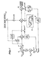
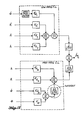
- Figure 1 illustrates a base line design. A detailed description of the operation of the base line design shown in figure 1 will not be presented here since it would be readily understood by anyone of ordinary skill in the art.
- ⁇ CF representing sink rate derived by complementary filtering from h and ⁇ baro
- h R representing radio altitude
- h representing vertical acceleration and 6 representing pitch rate.
- the signals are processed, as shown, through summing circuits, such as summer 12, gain blocks, such as block 14, filter blocks, such as blocks 16, 18 and logic block 20.
- the glideslope signal ⁇ ec is produced by a glideslope control block 22, such apparatus being well known in the prior art. This signal is coupled through to the output elevator command line 24 until such time as the various switches are activated, thereby initiating the aircraft flare. During flare-out, the signals received at the system's input are processed through the circuitry shown to produce the elevator command signal at output line 24.
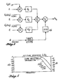
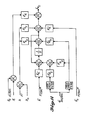
- Figure 2 illustrates a flare trajectory tracking law allowing gains higher than the system of figure 1.
- the altitude tracking error ⁇ h of the control law of figure 2 due to gust is substantially lower and the control bandwidth is substantially increased.
- the vertical acceleration (h) and pitch rate (6) feedback inner loop were traced to the vertical acceleration (h) and pitch rate (6) feedback inner loop.
- the vertical acceleration signal included signal components attributable to the location of the sensor relative to the airplane's center of gravity.
- the vertical acceleration signal was filtered to reduce high frequency noise components. The combination of these two factors resulted in poor inner loop signal quality to damp the high frequency pitch mode.
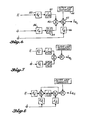
- Figure 6 illustrates one manner of accomplishing this goal.
- the vertical acceleration signal h is rolled off at frequencies ⁇ >1/ ⁇ by the lag circuit 30 after being amplified by a gain factor k h in gain block 32.
- a signal 8 representative of aircraft pitch attitude is brought in at frequencies ⁇ >1/ ⁇ by the washout circuit 34 which is preceded by a gain block 36.
- the two signals are summed in summer 40 and passed to a summer 42 where it is combined with conventional outer loop command signals from block 44 and the pitch rate signal 6 as amplified in gain block 46.
- the resultant output from summer 42 is the elevator control signal ⁇ ec .
- the 8 or lagged 9 signal does not need additional noise filtering, is not sensitive to sensor location and is an inherently more suitable damping signal for the high frequency pitch modes.
- This "complementary lagged ⁇ / ⁇ signal processing" eliminates the discussed problem in achieving a well damped high gain control law. It substantially maintains the superior turbulence response characteristics of a pure ⁇ / ⁇ inner loop system in the lower frequency range and improves the response in the high frequency range due to the elimination of ineffective elevator activity.
- the vertical acceleration signal can be expressed as a linear function of state variables governing the airplane dynamics.
- K 1 -Kg are constants
- h represents vertical position
- 8 and 9 represent pitch and pitch rate
- AV represents aircraft deviation from the reference speed
- ⁇ e represents elevator deflection
- 5T represents thrust change
- Ug represents horizontal gust velocity
- Wg vertical gust velocity
- the angle of attack ( ) terms have been expressed as a function of 8 and h. This equation, with the T, Ug and Wg terms neglected, was used to replace the vertical acceleration feedback signal in figure 2 with its equivalent signal components.
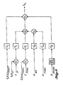
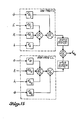
- control laws of figures 2 and 9 can be coupled together by means of a second order complementary filter.
- the result is shown in figure 15.
- This produces yet a better adherence to the ⁇ / ⁇ control law frequency response for low frequencies and the ⁇ / ⁇ control law frequency response for the high frequencies, as is shown in figure 16.
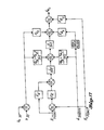
- the control law of figure 15 reduces to the form shown in figure 17.
- this control law features an inherent washout on the inner loop signals h and 8, thereby making the control law immune to static or low frequency inner loop sensor errors. This is of special importance in autoland control law design, where sensor bias errors can otherwise cause tracking offsets resulting in unacceptable autoland performance.
- the h and ⁇ lag filters are initialized at zero, with the h lag filter being initialized to carry the last computed elevator command from the previous control mode.
- the washout filters need not be initialized. Since none of the filters carry pre-flare signal information, pre-flare signal characteristics such as are exhibited by radar altitude cannot effect the flare.
- control law of figure 12 will be used to show how the complementary washout/lag filter may be employed to achieve the same result.
- a sink rate signal with desired characteristics can be synthesized from radio altitude h R and vertical acceleration from an inertial reference system (h IRS ) as:
- the complementary filter Since, in the control laws of figures 8,12 and 14, the complementary filter is the only one requiring initialization, it may be used to carry the last command from the previous control mode as the initial condition, thereby again avoiding pre-flare sensor history effects.
- This technique further provides implicit sink rate signal derivation and control law initialization preventing pre-flare signal histories (e.g. terrain effects on radio altitude) from affecting the flare control.
- a final control law is described having, besides the above features, the added characteristic of washing out all inner loop feedback signals, thereby further reducing the effects of low frequency sensor errors on the landing performance.
Landscapes
- Engineering & Computer Science (AREA)
- Aviation & Aerospace Engineering (AREA)
- Radar, Positioning & Navigation (AREA)
- Remote Sensing (AREA)
- Physics & Mathematics (AREA)
- General Physics & Mathematics (AREA)
- Automation & Control Theory (AREA)
- Control Of Position, Course, Altitude, Or Attitude Of Moving Bodies (AREA)
- Feedback Control In General (AREA)
Claims (8)
Applications Claiming Priority (2)
| Application Number | Priority Date | Filing Date | Title |
|---|---|---|---|
| US06/301,911 US4419732A (en) | 1981-09-14 | 1981-09-14 | Method and apparatus for an aircraft inner loop elevator control system |
| US301911 | 1999-04-29 |
Publications (2)
| Publication Number | Publication Date |
|---|---|
| EP0074493A1 EP0074493A1 (fr) | 1983-03-23 |
| EP0074493B1 true EP0074493B1 (fr) | 1987-03-11 |
Family
ID=23165419
Family Applications (1)
| Application Number | Title | Priority Date | Filing Date |
|---|---|---|---|
| EP82107195A Expired EP0074493B1 (fr) | 1981-09-14 | 1982-08-09 | Système de commande d'avion |
Country Status (3)
| Country | Link |
|---|---|
| US (1) | US4419732A (fr) |
| EP (1) | EP0074493B1 (fr) |
| DE (1) | DE3275665D1 (fr) |
Families Citing this family (11)
| Publication number | Priority date | Publication date | Assignee | Title |
|---|---|---|---|---|
| US5036469A (en) * | 1989-03-02 | 1991-07-30 | The Boeing Company | Pitch attitude command flight control system for landing flare |
| US5377937A (en) * | 1991-09-03 | 1995-01-03 | The Boeing Company | Aircraft flare control system utilizing an envelope limiter |
| US5901927A (en) * | 1996-07-18 | 1999-05-11 | Honeywell Inc. | Ground strike protection function for aircraft autopilot |
| CA2447553A1 (fr) * | 2000-11-03 | 2002-05-23 | President And Fellows Of Harvard College | Saframycines, analogues et leurs applications |
| US6676088B1 (en) * | 2002-10-07 | 2004-01-13 | Safe Flight Instrument Corporation | Flare control system |
| US7183054B2 (en) * | 2003-06-03 | 2007-02-27 | President And Fellows Of Harvard College | Assay for identifying biological targets of polynucleotide-binding compounds |
| EP1768899B1 (fr) * | 2004-07-16 | 2013-12-11 | Airbus Operations | Procede et dispositif d'amelioration de la manoeuvrabilite d'un aeronef lors des phases d'approche avant l'atterrissage puis d'arrondi |
| US8019492B2 (en) * | 2007-10-26 | 2011-09-13 | The Boeing Company | Operator fine tracking assist using sensor derived inputs |
| US8275496B2 (en) | 2007-11-21 | 2012-09-25 | The Boeing Company | Longitudinal and vertical gust feed forward compensation using lateral control surfaces |
| US8781653B2 (en) * | 2012-01-11 | 2014-07-15 | The Boeing Company | Quiet landing attitude modifier for airplane |
| US10816998B2 (en) | 2017-09-18 | 2020-10-27 | The Boeing Company | Airplane takeoff trims utilizing both stabilizers and elevators |
Family Cites Families (23)
| Publication number | Priority date | Publication date | Assignee | Title |
|---|---|---|---|---|
| US3447765A (en) * | 1965-05-27 | 1969-06-03 | Bendix Corp | Automatic control system for landing an aircraft |
| US3291421A (en) * | 1965-09-20 | 1966-12-13 | Lear Siegler Inc | Pitch controller for automatic landing |
| US3333795A (en) * | 1966-01-10 | 1967-08-01 | Collins Radio Co | Flare computer |
| US3523663A (en) * | 1968-03-28 | 1970-08-11 | Bendix Corp | Terminal flare controller |
| US3601339A (en) * | 1968-06-03 | 1971-08-24 | Elliott Brothers London Ltd | Aircraft-landing systems |
| US3604908A (en) * | 1969-05-19 | 1971-09-14 | Sperry Rand Corp | Landing control system for aircraft |
| US3578269A (en) * | 1969-06-11 | 1971-05-11 | Lear Siegler Inc | Automatic flare and altitude hold system |
| US3626163A (en) * | 1970-01-28 | 1971-12-07 | Us Army | Automatic landing system |
| US3652835A (en) * | 1970-05-14 | 1972-03-28 | Sperry Rand Corp | Aircraft glide slope coupler system |
| US3847328A (en) * | 1972-01-31 | 1974-11-12 | Boeing Co | Automatic go-around control system for aircraft |
| US3801049A (en) * | 1972-01-31 | 1974-04-02 | Boeing Co | Automatic approach landing and go-around pitch axis control system for aircraft |
| US4006871A (en) * | 1972-06-19 | 1977-02-08 | The Boeing Company | Automatic pitch axis control system for aircraft |
| US4164340A (en) * | 1973-03-19 | 1979-08-14 | The Boeing Company | Method and apparatus for determining when a glide slope signal exceeds a predetermined level |
| US3892373A (en) * | 1973-12-07 | 1975-07-01 | Bendix Corp | Integrated glide path/flare automatic flight control system |
| US3887148A (en) * | 1973-12-19 | 1975-06-03 | Sperry Rand Corp | Aircraft glide slope coupler and landing system |
| US3918662A (en) * | 1974-01-21 | 1975-11-11 | Boeing Co | Localizer lateral guidance control system |
| US3976267A (en) * | 1974-11-14 | 1976-08-24 | The Boeing Company | Vertical glide slope control system including complementary filter |
| US4032093A (en) * | 1975-06-27 | 1977-06-28 | The Boeing Company | Adaptive energy management for vertical speed control of an aircraft |
| US4104612A (en) * | 1977-02-03 | 1978-08-01 | Mcdonnell Douglas Corporation | Head-up display command bar generator |
| US4141522A (en) * | 1977-05-16 | 1979-02-27 | Boeing Commercial Airplane Company | Independent glide slope gain programming system |
| US4357661A (en) * | 1980-02-22 | 1982-11-02 | The Boeing Company | Aircraft landing control system |
| US4326253A (en) * | 1980-03-31 | 1982-04-20 | The Boeing Company | Lift control system for aircraft vertical path guidance |
| US4354237A (en) * | 1980-06-24 | 1982-10-12 | The Boeing Company | Method and apparatus for producing an aircraft flare path control signal |
-
1981
- 1981-09-14 US US06/301,911 patent/US4419732A/en not_active Expired - Lifetime
-
1982
- 1982-08-09 DE DE8282107195T patent/DE3275665D1/de not_active Expired
- 1982-08-09 EP EP82107195A patent/EP0074493B1/fr not_active Expired
Also Published As
| Publication number | Publication date |
|---|---|
| US4419732A (en) | 1983-12-06 |
| EP0074493A1 (fr) | 1983-03-23 |
| DE3275665D1 (en) | 1987-04-16 |
Similar Documents
| Publication | Publication Date | Title |
|---|---|---|
| US3892373A (en) | Integrated glide path/flare automatic flight control system | |
| EP0031619B1 (fr) | Système de commande de la trajectoire verticale d'un avion | |
| US5979835A (en) | Aircraft pitch-axis stability and command augmentation system | |
| US4326253A (en) | Lift control system for aircraft vertical path guidance | |
| EP0074493B1 (fr) | Système de commande d'avion | |
| US3743221A (en) | Aircraft flight control apparatus | |
| US3216676A (en) | Self-adaptive control system | |
| US5377937A (en) | Aircraft flare control system utilizing an envelope limiter | |
| US2841345A (en) | Glide path system with flare out | |
| US4354237A (en) | Method and apparatus for producing an aircraft flare path control signal | |
| US3333795A (en) | Flare computer | |
| GB2102159A (en) | Aircraft cruise speed control system | |
| US4006871A (en) | Automatic pitch axis control system for aircraft | |
| US4164340A (en) | Method and apparatus for determining when a glide slope signal exceeds a predetermined level | |
| US3801049A (en) | Automatic approach landing and go-around pitch axis control system for aircraft | |
| US3291421A (en) | Pitch controller for automatic landing | |
| US4797829A (en) | Flight control optimization system for multi-control surface aircraft | |
| US3994455A (en) | Automatic approach pitch axis control system for aircraft | |
| US3295796A (en) | Flight control system | |
| US3860800A (en) | Automatic pitch axis control system for aircraft | |
| US4485446A (en) | Aircraft lift control system with acceleration and attitude limiting | |
| US5424950A (en) | Vehicle control surface position feedback compensator for reducing vehicle oscillation | |
| US3976267A (en) | Vertical glide slope control system including complementary filter | |
| US3773281A (en) | Automatic flight control system using instrument landing system information and including inertial filtering means for reducing ils noise | |
| US3847328A (en) | Automatic go-around control system for aircraft |
Legal Events
| Date | Code | Title | Description |
|---|---|---|---|
| PUAI | Public reference made under article 153(3) epc to a published international application that has entered the european phase |
Free format text: ORIGINAL CODE: 0009012 |
|
| AK | Designated contracting states |
Designated state(s): DE FR GB IT NL SE |
|
| 17P | Request for examination filed |
Effective date: 19830916 |
|
| ITF | It: translation for a ep patent filed | ||
| GRAA | (expected) grant |
Free format text: ORIGINAL CODE: 0009210 |
|
| AK | Designated contracting states |
Kind code of ref document: B1 Designated state(s): DE FR GB IT NL SE |
|
| PG25 | Lapsed in a contracting state [announced via postgrant information from national office to epo] |
Ref country code: SE Effective date: 19870311 |
|
| REF | Corresponds to: |
Ref document number: 3275665 Country of ref document: DE Date of ref document: 19870416 |
|
| ET | Fr: translation filed | ||
| PLBE | No opposition filed within time limit |
Free format text: ORIGINAL CODE: 0009261 |
|
| STAA | Information on the status of an ep patent application or granted ep patent |
Free format text: STATUS: NO OPPOSITION FILED WITHIN TIME LIMIT |
|
| 26N | No opposition filed | ||
| PGFP | Annual fee paid to national office [announced via postgrant information from national office to epo] |
Ref country code: GB Payment date: 19920730 Year of fee payment: 11 |
|
| PGFP | Annual fee paid to national office [announced via postgrant information from national office to epo] |
Ref country code: FR Payment date: 19920828 Year of fee payment: 11 |
|
| ITTA | It: last paid annual fee | ||
| PGFP | Annual fee paid to national office [announced via postgrant information from national office to epo] |
Ref country code: NL Payment date: 19920831 Year of fee payment: 11 Ref country code: DE Payment date: 19920831 Year of fee payment: 11 |
|
| PG25 | Lapsed in a contracting state [announced via postgrant information from national office to epo] |
Ref country code: GB Effective date: 19930809 |
|
| PG25 | Lapsed in a contracting state [announced via postgrant information from national office to epo] |
Ref country code: NL Effective date: 19940301 |
|
| GBPC | Gb: european patent ceased through non-payment of renewal fee |
Effective date: 19930809 |
|
| NLV4 | Nl: lapsed or anulled due to non-payment of the annual fee | ||
| PG25 | Lapsed in a contracting state [announced via postgrant information from national office to epo] |
Ref country code: FR Effective date: 19940429 |
|
| PG25 | Lapsed in a contracting state [announced via postgrant information from national office to epo] |
Ref country code: DE Effective date: 19940503 |
|
| REG | Reference to a national code |
Ref country code: FR Ref legal event code: ST |