EP0074499A2 - Atténuateur optique - Google Patents
Atténuateur optique Download PDFInfo
- Publication number
- EP0074499A2 EP0074499A2 EP82107391A EP82107391A EP0074499A2 EP 0074499 A2 EP0074499 A2 EP 0074499A2 EP 82107391 A EP82107391 A EP 82107391A EP 82107391 A EP82107391 A EP 82107391A EP 0074499 A2 EP0074499 A2 EP 0074499A2
- Authority
- EP
- European Patent Office
- Prior art keywords
- metal layer
- waveguide
- optical
- optical waveguide
- attenuator
- Prior art date
- Legal status (The legal status is an assumption and is not a legal conclusion. Google has not performed a legal analysis and makes no representation as to the accuracy of the status listed.)
- Withdrawn
Links
Images
Classifications
-
- G—PHYSICS
- G02—OPTICS
- G02B—OPTICAL ELEMENTS, SYSTEMS OR APPARATUS
- G02B6/00—Light guides; Structural details of arrangements comprising light guides and other optical elements, e.g. couplings
- G02B6/24—Coupling light guides
- G02B6/26—Optical coupling means
- G02B6/264—Optical coupling means with optical elements between opposed fibre ends which perform a function other than beam splitting
- G02B6/266—Optical coupling means with optical elements between opposed fibre ends which perform a function other than beam splitting the optical element being an attenuator
Definitions
- the invention relates to an optical attenuator with fixed attenuation.
- Optical attenuators for fiber optic links are required, for example, if the dynamic range (approx. 20-30 dB) of the receiver is insufficient for incoming power that is too high or for measurements on transmission links. Since such a weakening of performance should take place as neutrally as possible, an increase in attenuation by increasing the distance between the two fiber end faces in a glass fiber plug connection is not an option.
- Relatively complicated optical attenuators, which contain lenses for beam shaping are for example from Nippon Electric Co. Ltd. offered (see also Optical Devices ' and Measuring Set Catalog, Nippon Electric Co., (1981)). They are available with both continuously adjustable damping and fixed damping.
- the object of the invention is to provide a simply constructed and producible attenuator of the type mentioned, in which no lenses are required.
- This attenuator according to the invention achieves largely mode-neutral and wavelength-independent attenuation, especially for fiber optic links.
- Attenuator advantageously designed as specified in claim 2.
- the optical waveguide consists of a glass fiber optical waveguide.
- the attenuation of an attenuator according to the invention is almost wavelength-independent in a wide spectral range, typically in a range from 700 nm to 1500 nm.
- An attenuator according to the invention can be produced in a simple manner as specified in claim 4.
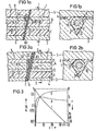
- the glass fiber optical waveguide 1 consisting of a core-cladding glass fiber is arranged in a V-shaped groove 2 produced by anisotropic etching in a silicon substrate 3 and fastened therein with optical cement 4.
- the optical putty 4 also glues the silicon substrate 3 to a cover plate 5 made of glass, which covers the fiber 1 and preferably touches the side of the fiber 1 facing away from the groove 2.
- the fiber core with the refractive index n 0 is denoted by 11 and the fiber cladding surrounding the core with a lower refractive index is denoted by 12.
- the fiber 1 extends a metal layer 6, the thickness of which is such that a desired rest of the radiation guided in the fiber 1 essentially in the region of the core 11 can radiate through the metal layer 6 (desired residual transmission), while the rest of the radiation is absorbed or reflected.
- the transmittance T decreases continuously with increasing layer thickness t, and an approximately exponential drop is obtained.
- the reflectivity R initially increases with: strong and then sought an independent t limit 'worth.
- the curve for the absorption A reaches a maximum after a steep increase at a specific t, then drops slightly and tends towards a limit value independent of t.
- the optical constants of metals in the wavelength range of interest from 700 nm to 1500 nm are only slightly dependent on the wavelength, the attenuation a in the spectral range under consideration is largely independent of the wavelength.
- Aluminum is an example of a metal.
- the metal layer must therefore not be arranged perpendicular to the fiber axis, but must be inclined from the vertical position by a certain angle ⁇ 0 with respect to the fiber axis, the minimum value of which arc sin (A N / n 0 ) is given, where AN is the numerical aperture of fiber 1 and n O den. mean refractive index of the fiber core 11.
- ⁇ 0 In order not to cause undesired discrimination between different polarization directions through the metal layer, ⁇ 0 must not be significantly greater than the minimum value.
- the two in Figures 1a) and 1b) and. 2a) and 2b) differ essentially only in the different ways of fastening the metal layer 6 in the fiber 1.
- the metal layer 6 is vapor-deposited directly onto a polished fiber end face 61, while in FIG In the embodiment according to FIGS. 2a) and 2b), a metallized film 7 is glued to a fiber end face.
- the manufacture of an attenuator can be carried out in such a way that the metal layer is either vapor-deposited directly onto an obliquely polished glass fiber end face or that a previously vapor-coated, thin plastic film, for example a Kapton film, is glued onto an obliquely polished glass fiber end face.
- a second fiber is glued in alignment with the first fiber to the metal layer or its plastic substrate.
- the individual manufacturing steps can be carried out similarly to the manufacture of fiber optic branches and wavelength division multiplex modules according to the beam splitter principle (see HF Mahlein, Design of Beam Splitters for 0ptical Fiber Tapping Elements, Siemens Forsch.-u.Design. Ber. 8 (1979 ) 136-140; A. Reichelt, G.
- V-shaped guide grooves produced by anisotropic etching of silicon can be used for fiber mounting. Use is made of this in the embodiments according to FIGS. 1a), b) and 2a), b).
- the optical cement that connects the fiber end faces 61, 62 to the metal layer 6 or the plastic film 7 is FIGS. 1a and 2a. designated 63.
- the entire attenuator can be installed in a housing with connector flanges at the input and output. If the connector flanges are omitted, the attenuator can also be spliced into a glass fiber link.
Landscapes
- Physics & Mathematics (AREA)
- General Physics & Mathematics (AREA)
- Optics & Photonics (AREA)
- Optical Couplings Of Light Guides (AREA)
- Light Guides In General And Applications Therefor (AREA)
- Optical Elements Other Than Lenses (AREA)
- Mechanical Coupling Of Light Guides (AREA)
- Optical Fibers, Optical Fiber Cores, And Optical Fiber Bundles (AREA)
Applications Claiming Priority (2)
| Application Number | Priority Date | Filing Date | Title |
|---|---|---|---|
| DE3136584 | 1981-09-15 | ||
| DE19813136584 DE3136584A1 (de) | 1981-09-15 | 1981-09-15 | Optisches daempfungsglied |
Publications (2)
| Publication Number | Publication Date |
|---|---|
| EP0074499A2 true EP0074499A2 (fr) | 1983-03-23 |
| EP0074499A3 EP0074499A3 (fr) | 1983-06-29 |
Family
ID=6141706
Family Applications (1)
| Application Number | Title | Priority Date | Filing Date |
|---|---|---|---|
| EP82107391A Withdrawn EP0074499A3 (fr) | 1981-09-15 | 1982-08-13 | Atténuateur optique |
Country Status (3)
| Country | Link |
|---|---|
| EP (1) | EP0074499A3 (fr) |
| JP (1) | JPS5860704A (fr) |
| DE (1) | DE3136584A1 (fr) |
Cited By (7)
| Publication number | Priority date | Publication date | Assignee | Title |
|---|---|---|---|---|
| EP0246166A1 (fr) * | 1986-05-15 | 1987-11-19 | RADIALL INDUSTRIE, Société Anonyme dite: | Atténuateur pour fibres optiques monomode et procédé pour sa fabrication |
| EP0341919A3 (en) * | 1988-05-06 | 1990-09-12 | Mitsubishi Rayon Co., Ltd. | Light attenuator and process for fabrication thereof |
| US5319733A (en) * | 1992-01-02 | 1994-06-07 | Adc Telecommunications, Inc. | Variable fiber optical attenuator |
| US5588087A (en) * | 1992-01-02 | 1996-12-24 | Adc Telecommunications, Inc. | Overlapping fusion attenuator |
| EP0731576A3 (fr) * | 1995-03-06 | 1998-10-21 | International Business Machines Corporation | Egalisation de gain utilisant des guides d'ondes monolithiques planaires à diffraction comme multiplexeurs et démultiplexeurs |
| EP0816881A3 (fr) * | 1996-07-05 | 2003-07-30 | Molex Incorporated | Atténuateur à fibre optique |
| CN106324758A (zh) * | 2016-10-17 | 2017-01-11 | 苏州安捷讯光电科技股份有限公司 | 光纤回路器及其制作方法、光纤连接器及其制作方法 |
Families Citing this family (3)
| Publication number | Priority date | Publication date | Assignee | Title |
|---|---|---|---|---|
| JPS62121405A (ja) * | 1985-11-22 | 1987-06-02 | Nec Corp | 光減衰器 |
| DE3701421A1 (de) * | 1987-01-20 | 1988-07-28 | Standard Elektrik Lorenz Ag | Optische steckverbindung |
| JPH04101106A (ja) * | 1990-08-20 | 1992-04-02 | Nec Corp | 光ファイバ加工形デバイス |
Family Cites Families (3)
| Publication number | Priority date | Publication date | Assignee | Title |
|---|---|---|---|---|
| DE2418994C2 (de) * | 1974-04-19 | 1982-11-25 | Siemens AG, 1000 Berlin und 8000 München | Wellenleiterstruktur mit Dünnschichtfilter und Verfahren zu deren Herstellung |
| DE2851654A1 (de) * | 1978-11-29 | 1980-06-26 | Siemens Ag | Koppelelement zum auskoppeln eines lichtanteils aus einem optischen wellenleiter und wiedereinkoppeln desselben in einen abzweigenden optischen wellenleiter sowie verfahren zur herstellung des elements |
| DE2851679C2 (de) * | 1978-11-29 | 1983-02-17 | Siemens AG, 1000 Berlin und 8000 München | Verfahren zur Herstellung eines Verzweigerelements nach dem Strahlteilerprinzip |
-
1981
- 1981-09-15 DE DE19813136584 patent/DE3136584A1/de not_active Withdrawn
-
1982
- 1982-08-13 EP EP82107391A patent/EP0074499A3/fr not_active Withdrawn
- 1982-09-13 JP JP57159415A patent/JPS5860704A/ja active Pending
Cited By (9)
| Publication number | Priority date | Publication date | Assignee | Title |
|---|---|---|---|---|
| EP0246166A1 (fr) * | 1986-05-15 | 1987-11-19 | RADIALL INDUSTRIE, Société Anonyme dite: | Atténuateur pour fibres optiques monomode et procédé pour sa fabrication |
| FR2598820A1 (fr) * | 1986-05-15 | 1987-11-20 | Radiall Ind | Attenuateur pour fibres optiques monomode et procede pour sa fabrication. |
| US4787700A (en) * | 1986-05-15 | 1988-11-29 | Radiall Industrie | Attenuator for single-mode optical fibers and process for its fabrication |
| EP0341919A3 (en) * | 1988-05-06 | 1990-09-12 | Mitsubishi Rayon Co., Ltd. | Light attenuator and process for fabrication thereof |
| US5319733A (en) * | 1992-01-02 | 1994-06-07 | Adc Telecommunications, Inc. | Variable fiber optical attenuator |
| US5588087A (en) * | 1992-01-02 | 1996-12-24 | Adc Telecommunications, Inc. | Overlapping fusion attenuator |
| EP0731576A3 (fr) * | 1995-03-06 | 1998-10-21 | International Business Machines Corporation | Egalisation de gain utilisant des guides d'ondes monolithiques planaires à diffraction comme multiplexeurs et démultiplexeurs |
| EP0816881A3 (fr) * | 1996-07-05 | 2003-07-30 | Molex Incorporated | Atténuateur à fibre optique |
| CN106324758A (zh) * | 2016-10-17 | 2017-01-11 | 苏州安捷讯光电科技股份有限公司 | 光纤回路器及其制作方法、光纤连接器及其制作方法 |
Also Published As
| Publication number | Publication date |
|---|---|
| EP0074499A3 (fr) | 1983-06-29 |
| JPS5860704A (ja) | 1983-04-11 |
| DE3136584A1 (de) | 1983-03-31 |
Similar Documents
| Publication | Publication Date | Title |
|---|---|---|
| DE3687944T2 (de) | Kopplungselement fuer monomodefaser und dieses aufweisende uebertragungssystem. | |
| DE69714378T2 (de) | Vorrichtung mit Lichtwellenleiter-Abzweiger | |
| DE3877597T2 (de) | Verbindung von optischen fasern. | |
| EP0026379B1 (fr) | Dispositif pour coupler latéralement la lumière dans un guide d'ondes optiques en fibre de verre | |
| DE3886935T2 (de) | Optisches koppelelement. | |
| DE69510406T2 (de) | Faseroptische Lichteinkopplungsschnittstelle mit vergrösserter Einfallsfläche | |
| EP0012189B1 (fr) | Elément coupleur pour dériver une fraction de lumière d'un guide d'ondes optique comprenant une fibre entourée d'une gaine | |
| DE2851667C2 (fr) | ||
| EP0053324B2 (fr) | Diviseur optique | |
| DE69426707T2 (de) | Eine optische vorrichtung und ihr herstellungsverfahren | |
| DE69620130T2 (de) | Optisches Sender-Empfänger-Modul | |
| DE2745940A1 (de) | Optisches schaltkreiselement | |
| CH644975A5 (de) | Lichtleitfaser-richtkoppler und dessen verwendung in einer sende-/empfangseinrichtung. | |
| DE3007180A1 (de) | Optische kopplungsanordnung | |
| DE2840493A1 (de) | Frequenzselektives optisches lichtverteilerelement und verfahren zu seiner herstellung | |
| EP0074499A2 (fr) | Atténuateur optique | |
| DE69900660T2 (de) | Vorrichtung mit einem dispersiven Lichtwellenleiter-Abzweiger | |
| DE69626559T2 (de) | Laserlichtquelle und Herstellungsverfahren | |
| DE10201127A1 (de) | Anordnung zum Ein- und/oder Auskoppeln optischer Signale mindestens eines optischen Datenkanals in bzw. aus einem Lichtwellenleiter | |
| EP0416640A2 (fr) | MÀ©thode de fabrication d'un coupleur optique fusionné et coupleur ainsi fabriquÀ© | |
| DE10314495B3 (de) | Optische Koppeleinheit | |
| EP1124146B1 (fr) | Spectromètre optique avec guide d'onde optique | |
| DE3432743A1 (de) | Optisches koppelglied | |
| DE2851654A1 (de) | Koppelelement zum auskoppeln eines lichtanteils aus einem optischen wellenleiter und wiedereinkoppeln desselben in einen abzweigenden optischen wellenleiter sowie verfahren zur herstellung des elements | |
| DE3606682C1 (en) | Optical fibre arrangement for microoptical grating multiplexers and demultiplexers |
Legal Events
| Date | Code | Title | Description |
|---|---|---|---|
| PUAI | Public reference made under article 153(3) epc to a published international application that has entered the european phase |
Free format text: ORIGINAL CODE: 0009012 |
|
| AK | Designated contracting states |
Designated state(s): AT BE CH FR GB IT LI LU NL SE |
|
| PUAL | Search report despatched |
Free format text: ORIGINAL CODE: 0009013 |
|
| AK | Designated contracting states |
Designated state(s): AT BE CH FR GB IT LI LU NL SE |
|
| 17P | Request for examination filed |
Effective date: 19831222 |
|
| STAA | Information on the status of an ep patent application or granted ep patent |
Free format text: STATUS: THE APPLICATION IS DEEMED TO BE WITHDRAWN |
|
| 18D | Application deemed to be withdrawn |
Effective date: 19850809 |
|
| RIN1 | Information on inventor provided before grant (corrected) |
Inventor name: MAHLEIN, HANS, DR.RER.NAT. |