EP0074531A1 - Dispositif d'injection de carburant - Google Patents
Dispositif d'injection de carburant Download PDFInfo
- Publication number
- EP0074531A1 EP0074531A1 EP82107780A EP82107780A EP0074531A1 EP 0074531 A1 EP0074531 A1 EP 0074531A1 EP 82107780 A EP82107780 A EP 82107780A EP 82107780 A EP82107780 A EP 82107780A EP 0074531 A1 EP0074531 A1 EP 0074531A1
- Authority
- EP
- European Patent Office
- Prior art keywords
- fuel
- internal combustion
- combustion engine
- compressor
- air
- Prior art date
- Legal status (The legal status is an assumption and is not a legal conclusion. Google has not performed a legal analysis and makes no representation as to the accuracy of the status listed.)
- Withdrawn
Links
Images
Classifications
-
- F—MECHANICAL ENGINEERING; LIGHTING; HEATING; WEAPONS; BLASTING
- F02—COMBUSTION ENGINES; HOT-GAS OR COMBUSTION-PRODUCT ENGINE PLANTS
- F02M—SUPPLYING COMBUSTION ENGINES IN GENERAL WITH COMBUSTIBLE MIXTURES OR CONSTITUENTS THEREOF
- F02M69/00—Low-pressure fuel-injection apparatus ; Apparatus with both continuous and intermittent injection; Apparatus injecting different types of fuel
- F02M69/04—Injectors peculiar thereto
- F02M69/042—Positioning of injectors with respect to engine, e.g. in the air intake conduit
-
- F—MECHANICAL ENGINEERING; LIGHTING; HEATING; WEAPONS; BLASTING
- F02—COMBUSTION ENGINES; HOT-GAS OR COMBUSTION-PRODUCT ENGINE PLANTS
- F02B—INTERNAL-COMBUSTION PISTON ENGINES; COMBUSTION ENGINES IN GENERAL
- F02B29/00—Engines characterised by provision for charging or scavenging not provided for in groups F02B25/00, F02B27/00 or F02B33/00 - F02B39/00; Details thereof
- F02B29/04—Cooling of air intake supply
- F02B29/0481—Intake air cooling by means others than heat exchangers, e.g. by rotating drum regenerators, cooling by expansion or by electrical means
-
- F—MECHANICAL ENGINEERING; LIGHTING; HEATING; WEAPONS; BLASTING
- F02—COMBUSTION ENGINES; HOT-GAS OR COMBUSTION-PRODUCT ENGINE PLANTS
- F02M—SUPPLYING COMBUSTION ENGINES IN GENERAL WITH COMBUSTIBLE MIXTURES OR CONSTITUENTS THEREOF
- F02M69/00—Low-pressure fuel-injection apparatus ; Apparatus with both continuous and intermittent injection; Apparatus injecting different types of fuel
- F02M69/04—Injectors peculiar thereto
- F02M69/042—Positioning of injectors with respect to engine, e.g. in the air intake conduit
- F02M69/044—Positioning of injectors with respect to engine, e.g. in the air intake conduit for injecting into the intake conduit downstream of an air throttle valve
-
- Y—GENERAL TAGGING OF NEW TECHNOLOGICAL DEVELOPMENTS; GENERAL TAGGING OF CROSS-SECTIONAL TECHNOLOGIES SPANNING OVER SEVERAL SECTIONS OF THE IPC; TECHNICAL SUBJECTS COVERED BY FORMER USPC CROSS-REFERENCE ART COLLECTIONS [XRACs] AND DIGESTS
- Y02—TECHNOLOGIES OR APPLICATIONS FOR MITIGATION OR ADAPTATION AGAINST CLIMATE CHANGE
- Y02T—CLIMATE CHANGE MITIGATION TECHNOLOGIES RELATED TO TRANSPORTATION
- Y02T10/00—Road transport of goods or passengers
- Y02T10/10—Internal combustion engine [ICE] based vehicles
- Y02T10/12—Improving ICE efficiencies
Definitions
- the invention is based on a fuel injection system according to the preamble of the main claim.
- a fuel injection system is already known in which the injection takes place downstream of the turbocharger. This has the disadvantage that the air temperatures before entering the cylinders of the internal combustion engine rise to over 100 ° C in some cases, which results in lower filling and poorer efficiency of the internal combustion engine.
- the fuel injection system according to the invention with the characterizing features of the main claim has the advantage that the fuel injected upstream of the compressor due to its energy requirement during evaporation leads to cooling of the intake air and the compressor, which in addition to an extension of the life of the compressor due to less wear higher degree of filling of the internal combustion engine and thus an increase in performance is achieved. Further advantages are an earlier ignition timing with the result of lower fuel consumption and better efficiency, which reduces harmful components in the exhaust gas.
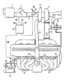
- the combustion air flows through an air filter 1 into an intake manifold section 2, in which an air measuring element 3 of a known type, for example a hot wire air mass meter or a damper air volume meter, is arranged.
- an air measuring element 3 of a known type, for example a hot wire air mass meter or a damper air volume meter
- a compressor 5 for example a turbocharger of known type, which compresses the air quantity drawn in by an internal combustion engine 4
- individual intake pipes 8 branch off from the intake pipe section 6 and lead to the individual cylinders of the internal combustion engine 4.
- the illustrated internal combustion engine 4 is intended to be a 6-cylinder internal combustion engine.
- At 10 is one Exhaust gas line, which leads to an exhaust gas turbine 11, which is rigidly coupled to the compressor 5 and is driven by the heated and highly compressed exhaust gas.
- a bypass valve 12 is used to open when the maximum permissible boost pressure in the intake manifold section 6 is reached and to allow part of the exhaust gas to flow past the exhaust gas turbine 11.
- a main injection valve 14 is arranged on each individual intake manifold 8, via which fuel can be injected immediately before the intake valve of each cylinder.
- the main injection valves 14 are connected to a fuel distributor line 15, into which fuel is conveyed from a fuel tank 18 by a fuel pump 17 driven by an electric motor 16.
- a pressure control valve 19 ensures a constant fuel pressure in the fuel rail 15.
- the exemplary embodiment of a fuel injection system shown, for example, is to be an electronic fuel injection system with main injection valves 14 designed as electromagnetic valves.
- the main injection valves 14 are activated via a control line 20 by an electronic control unit 21 Known type depending on the operating parameters of the internal combustion engine such as speed 22, air volume 23, throttle valve position 24, temperature 25 and others.
- an auxiliary injection valve 27 is therefore arranged upstream of the compressor 5 on the intake manifold section 2 and is connected to the fuel rail 15 via a branch line 28.
- Evaporation of the fuel injected via the additional injection valve 27 upstream of the compressor 5 removes heat from the intake air, which not only reduces the compressor temperature, but also reduces the temperature of the air supplied to the cylinders of the internal combustion engine 4, which results in the degree of filling of the individual cylinders increases, which results in an increase in performance of the internal combustion engine. This also results in an earlier ignition timing and better efficiency, which reduces fuel consumption and the proportion of toxic exhaust gas components.
- the otherwise inventive charge air cooler can be eliminated or at least reduced by the injection according to the invention via the additional injection valve 27 upstream of the compressor.
- the additional injection valve 27 can also be controlled electromagnetically by the electronic control unit 21.
- the control of the additional injection valve 27 can advantageously take place in such a way that below the operating temperature of the internal combustion engine of approximately 80 ° C. there is no injection via the additional injection valve 27, that is to say the additional injection valve is closed.
- the amount of fuel injected in each case via the main injection valves 14 should be reduced in proportion to the amount of fuel injected via the additional injection valve 27.
- the configuration according to the invention of a fuel injection system with an additional injection valve 27 for injecting fuel upstream of the compressor is not limited to use in an electronic fuel injection system. Rather, an additional injection valve can also be provided in an equivalent configuration in a mechanical fuel injection system, which injects fuel under the conditions described upstream of the compressor 5 into the intake manifold section 2, the injection quantities being reduced in a corresponding manner via the main injection valves 14.
Landscapes
- Engineering & Computer Science (AREA)
- Chemical & Material Sciences (AREA)
- Combustion & Propulsion (AREA)
- Mechanical Engineering (AREA)
- General Engineering & Computer Science (AREA)
- Physics & Mathematics (AREA)
- Thermal Sciences (AREA)
- Electrical Control Of Air Or Fuel Supplied To Internal-Combustion Engine (AREA)
- Fuel-Injection Apparatus (AREA)
- Supercharger (AREA)
- Output Control And Ontrol Of Special Type Engine (AREA)
Applications Claiming Priority (2)
| Application Number | Priority Date | Filing Date | Title |
|---|---|---|---|
| DE19813135791 DE3135791A1 (de) | 1981-09-10 | 1981-09-10 | Kraftstoffeinspritzpumpe |
| DE3135791 | 1981-09-10 |
Publications (1)
| Publication Number | Publication Date |
|---|---|
| EP0074531A1 true EP0074531A1 (fr) | 1983-03-23 |
Family
ID=6141258
Family Applications (1)
| Application Number | Title | Priority Date | Filing Date |
|---|---|---|---|
| EP82107780A Withdrawn EP0074531A1 (fr) | 1981-09-10 | 1982-08-25 | Dispositif d'injection de carburant |
Country Status (3)
| Country | Link |
|---|---|
| EP (1) | EP0074531A1 (fr) |
| JP (1) | JPS5857069A (fr) |
| DE (1) | DE3135791A1 (fr) |
Cited By (4)
| Publication number | Priority date | Publication date | Assignee | Title |
|---|---|---|---|---|
| US4474161A (en) * | 1982-01-30 | 1984-10-02 | Robert Bosch Gmbh | Method for mixture formation for mixture-compressing internal combustion engines and fuel supply system for performing the method |
| US4498443A (en) * | 1982-05-24 | 1985-02-12 | Honda Motor Co., Ltd. | Fuel supply control method having fail-safe function for abnormalities in intake passage pressure detecting means of an internal combustion engine having a turbocharger |
| EP0235835A1 (fr) * | 1986-02-04 | 1987-09-09 | ALFA LANCIA INDUSTRIALE S.p.A. | Appareil d'alimentation de carburant pour moteur à combustion interne |
| EP1321658A1 (fr) * | 2001-12-18 | 2003-06-25 | Guido Parisi | Jeu de pièces détachées pour moteurs Diesel |
Families Citing this family (3)
| Publication number | Priority date | Publication date | Assignee | Title |
|---|---|---|---|---|
| DE4122553A1 (de) * | 1991-07-08 | 1993-01-14 | Bayerische Motoren Werke Ag | Brennkraftmaschine fuer betrieb mit benzin oder alkohol |
| DE4131626A1 (de) * | 1991-09-23 | 1993-03-25 | Kloeckner Humboldt Deutz Ag | Verfahren zur steuerung der kraftstoffeinspritzung von einem kraftstoff und einer fluessigkeit |
| DE102021101413A1 (de) | 2021-01-22 | 2022-07-28 | Ford Global Technologies, Llc | Verfahren zum Betreiben einer Verbrennungsmaschinenanordnung während eines Spülzustandes |
Citations (3)
| Publication number | Priority date | Publication date | Assignee | Title |
|---|---|---|---|---|
| FR1079660A (fr) * | 1952-07-30 | 1954-12-01 | Daimler Benz Ag | Disposition de carburateurs sur des moteurs à combustion interne avec soufflerie decharge |
| DE2737849A1 (de) * | 1977-08-23 | 1979-03-08 | Volkswagenwerk Ag | Verfahren zum betrieb einer mehrzylindrigen otto-brennkraftmaschine mit abgasturboaufladung und brennkraftmaschine zur durchfuehrung des verfahrens |
| DE2825945A1 (de) * | 1978-06-14 | 1979-12-20 | Rudolf Dr Wieser | Kuehlsystem fuer fahrzeugmotor |
-
1981
- 1981-09-10 DE DE19813135791 patent/DE3135791A1/de not_active Withdrawn
-
1982
- 1982-08-25 EP EP82107780A patent/EP0074531A1/fr not_active Withdrawn
- 1982-09-09 JP JP57156000A patent/JPS5857069A/ja active Pending
Patent Citations (3)
| Publication number | Priority date | Publication date | Assignee | Title |
|---|---|---|---|---|
| FR1079660A (fr) * | 1952-07-30 | 1954-12-01 | Daimler Benz Ag | Disposition de carburateurs sur des moteurs à combustion interne avec soufflerie decharge |
| DE2737849A1 (de) * | 1977-08-23 | 1979-03-08 | Volkswagenwerk Ag | Verfahren zum betrieb einer mehrzylindrigen otto-brennkraftmaschine mit abgasturboaufladung und brennkraftmaschine zur durchfuehrung des verfahrens |
| DE2825945A1 (de) * | 1978-06-14 | 1979-12-20 | Rudolf Dr Wieser | Kuehlsystem fuer fahrzeugmotor |
Cited By (5)
| Publication number | Priority date | Publication date | Assignee | Title |
|---|---|---|---|---|
| US4474161A (en) * | 1982-01-30 | 1984-10-02 | Robert Bosch Gmbh | Method for mixture formation for mixture-compressing internal combustion engines and fuel supply system for performing the method |
| US4498443A (en) * | 1982-05-24 | 1985-02-12 | Honda Motor Co., Ltd. | Fuel supply control method having fail-safe function for abnormalities in intake passage pressure detecting means of an internal combustion engine having a turbocharger |
| EP0235835A1 (fr) * | 1986-02-04 | 1987-09-09 | ALFA LANCIA INDUSTRIALE S.p.A. | Appareil d'alimentation de carburant pour moteur à combustion interne |
| EP1321658A1 (fr) * | 2001-12-18 | 2003-06-25 | Guido Parisi | Jeu de pièces détachées pour moteurs Diesel |
| WO2003052258A1 (fr) * | 2001-12-18 | 2003-06-26 | Guido Parisi | Kit pour moteur diesel |
Also Published As
| Publication number | Publication date |
|---|---|
| DE3135791A1 (de) | 1983-03-24 |
| JPS5857069A (ja) | 1983-04-05 |
Similar Documents
| Publication | Publication Date | Title |
|---|---|---|
| AT400473B (de) | Brennkraftmaschine mit abgasturbolader | |
| DE4041628A1 (de) | Gemischverdichtende brennkraftmaschine mit sekundaerlufteinblasung und mit luftmassenmessung im saugrohr | |
| WO2017157754A1 (fr) | Moteur à combustion interne et procédé permettant de faire fonctionner un moteur à combustion interne | |
| WO2005088114A1 (fr) | Dispositif d'injection de carburant pour moteur à combustion interne | |
| CH639727A5 (de) | Kolben-brennkraftmaschine mit mindestens zwei abgasturboladern. | |
| DE2836870A1 (de) | Kraftfahrzeug mit abgasturbolader | |
| EP3417164B1 (fr) | Moteur à combustion interne et procédé permettant de faire fonctionner un moteur à combustion interne | |
| DE102017116648A1 (de) | Verbrennungskraftmaschine, insbesondere für ein Kraftfahrzeug, sowie Verfahren zum Betreiben einer solchen Verbrennungskraftmaschine | |
| DE1935155C3 (de) | Brennkraftmaschine mit Ausnutzung der Schwingungen der Frischgase in der Einlaßleitung | |
| DE202015100452U1 (de) | Vorrichtung zum Vermindern der Klopfneigung eines fremd gezündeten aufgeladenen Verbrennungsmotors | |
| DE102008055896A1 (de) | Turboladeranordnung für eine Brennkraftmaschine | |
| DE3203179C2 (fr) | ||
| EP0074531A1 (fr) | Dispositif d'injection de carburant | |
| DE4320045A1 (de) | Aufgeladene Brennkraftmaschine | |
| DE102017222770A1 (de) | Verfahren zum Betreiben einer Kurbelgehäuseentlüftungseinrichtung eines Verbrennungsmotors für ein Kraftfahrzeug, sowie ein Verbrennungsmotor mit einer solchen Kurbelgehäuseentlüftungseinrichtung | |
| DE102015214107A1 (de) | Verbrennungskraftmaschine mit einem Verdichter und einem zusätzlichen Kompressor | |
| DE102015200706A1 (de) | Verfahren zum Vermindern der Klopfneigung eines fremd gezündeten aufgeladenen Verbrennungsmotors und Vorrichtung zum Durchführen des Verfahrens | |
| DE102018112292A1 (de) | Brennkraftmaschine mit Abgasrückführung über Abgasverdichter und Druckspeicher | |
| DE102014019556A1 (de) | Verfahren zum Betreiben einer Verbrennungskraftmaschine für einen Kraftwagen | |
| DE2836215A1 (de) | Kraftstoffversorgungsanlage | |
| EP0022583B1 (fr) | Dispositif de commande d'un conduit de dérivation pour un moteur à combustion interne suralimenté par un turbocompresseur | |
| DE1601374A1 (de) | Selbstzuendende,luftverdichtende Brennkraftmaschine,insbesondere fuer den Betrieb mit zuendunwilligen Kraftstoffen | |
| DE3043584A1 (de) | Einspritz-brennkraftmaschine | |
| DE102019213283A1 (de) | Brennkraftmaschine mit Sauerstoffgenerator und Einblasung von sauerstoffreichem Gas | |
| CH631239A5 (en) | Method for the operation of an internal combustion engine with turbocharging |
Legal Events
| Date | Code | Title | Description |
|---|---|---|---|
| PUAI | Public reference made under article 153(3) epc to a published international application that has entered the european phase |
Free format text: ORIGINAL CODE: 0009012 |
|
| 17P | Request for examination filed |
Effective date: 19820825 |
|
| AK | Designated contracting states |
Designated state(s): DE FR GB IT |
|
| STAA | Information on the status of an ep patent application or granted ep patent |
Free format text: STATUS: THE APPLICATION IS DEEMED TO BE WITHDRAWN |
|
| 18D | Application deemed to be withdrawn |
Effective date: 19840410 |
|
| RIN1 | Information on inventor provided before grant (corrected) |
Inventor name: SEEBALD, LUTZ |