EP0074698A1 - Kabelleiter - Google Patents
Kabelleiter Download PDFInfo
- Publication number
- EP0074698A1 EP0074698A1 EP82300895A EP82300895A EP0074698A1 EP 0074698 A1 EP0074698 A1 EP 0074698A1 EP 82300895 A EP82300895 A EP 82300895A EP 82300895 A EP82300895 A EP 82300895A EP 0074698 A1 EP0074698 A1 EP 0074698A1
- Authority
- EP
- European Patent Office
- Prior art keywords
- cable ladder
- stringer
- cable
- rungs
- ladder
- Prior art date
- Legal status (The legal status is an assumption and is not a legal conclusion. Google has not performed a legal analysis and makes no representation as to the accuracy of the status listed.)
- Withdrawn
Links
- 238000010276 construction Methods 0.000 claims abstract description 9
- 230000008878 coupling Effects 0.000 description 3
- 238000010168 coupling process Methods 0.000 description 3
- 238000005859 coupling reaction Methods 0.000 description 3
- 229910000831 Steel Inorganic materials 0.000 description 2
- 239000010959 steel Substances 0.000 description 2
Images


Classifications
-
- H—ELECTRICITY
- H02—GENERATION; CONVERSION OR DISTRIBUTION OF ELECTRIC POWER
- H02G—INSTALLATION OF ELECTRIC CABLES OR LINES, OR OF COMBINED OPTICAL AND ELECTRIC CABLES OR LINES
- H02G3/00—Installations of electric cables or lines or protective tubing therefor in or on buildings, equivalent structures or vehicles
- H02G3/02—Details
- H02G3/04—Protective tubing or conduits, e.g. cable ladders or cable troughs
- H02G3/0456—Ladders or other supports
Definitions
- This invention relates to ladder-like structures for supporting electric cables and/or service pipes, which structures comprise a pair of elongate side members (generally and hereinafter referrred to as “stringers”) and, extending transversely between and secured to the stringers at spaced positions along their lengths, a plurality of elongate support members (generally and hereinafter referred to as “rungs").
- ladder-like structures may also include coupling components such as bends for supporting electric cables and/or service pipes as the direction and/or plane in which they extend gradually changes, tee-connectors and cross-connectors, all such coupling components having, as common features, at least one pair of stringers interconnected by mutually spaced transversely extending rungs.
- coupling components such as bends for supporting electric cables and/or service pipes as the direction and/or plane in which they extend gradually changes, tee-connectors and cross-connectors, all such coupling components having, as common features, at least one pair of stringers interconnected by
- each stringer is of such a transverse cross-sectional shape that the cable ladder can be arranged to extend lengthwise above, and to nest between the stringers of, another cable ladder of substantially identical construction.
- each stringer of the cable ladder has such a transverse cross-sectional shape that, when the cable ladder is nesting between the stringers of another cable ladder of substantially identical construction, the cable ladder will be supported on the rungs of the other cable ladder.
- each stringer extending from the rungs to that longitudinal edge of the stringer which will be uppermost when the cable ladder is arranged to lie in a substantially horizontal plane may be so inclined to the cable-supporting surfaces of the rungs that the distance between the inner surface of the stringer and the central longitudinal axis of the cable ladder increases smoothly in a direction from the rungs to said longitudinal edge of the stringer but, preferably, to provide the stringer with additional inherent strength, at least that portion of the stringer extending between the rungs and said longitudinal edge has a multi-stepped transverse cross-sectional shape, the distance between the inner surface of one longitudinally extending part of the stringer and the central longitudinal axis of the cable ladder at each step being greater than said distance at a neighbouring longitudinally extending part of the stringer.
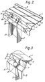
- the cable ladder comprises two steel stringers 1 of substantially channel-shaped cross-section arranged substantially parallel to one another and, extending transversely between and secured to the stringers at spaced positions along their lengths, a plurality of steel rungs 2 each of channel-shaped cross-section.
- Each stringer 1 includes a base 3, a flange 9 folded over outwardly of the cable ladder, and an inwardly extending flange 6 interconnected by two adjoining longitudinally extending surfaces 4 and 5 which are inclined at obtuse angles to the base 3 and the flange 6, respectively, to form, in the outer side face of the stringer, a longitudinally extending groove 7.
- each stringer 1 extending between the rungs 2 and its flange 9 is divided transversely of its length by two transversely. spaced, longitudinally extending steps into parts 11, 12 and 13, the distance between the inner surface of the part 13 and the central longitudinal axis of the cable ladder being greater-than the distance between the inner surface of the part 12 and the central longitudinal axis of the cable ladder, and the distance between the inner surface of the part 12 and the central longitudinal axis of the cable ladder being greater than the distance between the inner surface of the part 11 and the central longitudinal axis of the cable ladder.
- each stringer 1 having longitudinally extending surfaces 4 and 5 has at each of a plurality of longitudinally spaced positions along its length a pair of longitudinally spaced, transversely extending slots 8.
- End parts 18 of the side wall 17 of a rung 2 protrude through a pair of slots 8 and are folded, as shown in Figures 2 and 3, to lie in the groove 7 and to lock the rung permanently to the stringer.
- the end faces of the rungs 2 abut the inner surfaces of the parts ll of the stringers 1.
- the nestable cable ladder of the present invention has the important advantage that it facilitates transportation of cable ladders generally and especially when a ladder-like support structure is being erected at a site where space is limited, for example along a tunnel. Storage of cable ladders of substantially identical construction within a factory, on site or elsewhere is also facilitated because a substantial saving in space is provided.
Landscapes
- Engineering & Computer Science (AREA)
- Architecture (AREA)
- Civil Engineering (AREA)
- Structural Engineering (AREA)
- Ladders (AREA)
Applications Claiming Priority (2)
| Application Number | Priority Date | Filing Date | Title |
|---|---|---|---|
| GB8127496 | 1981-09-11 | ||
| GB8127496 | 1981-09-11 |
Publications (1)
| Publication Number | Publication Date |
|---|---|
| EP0074698A1 true EP0074698A1 (de) | 1983-03-23 |
Family
ID=10524442
Family Applications (1)
| Application Number | Title | Priority Date | Filing Date |
|---|---|---|---|
| EP82300895A Withdrawn EP0074698A1 (de) | 1981-09-11 | 1982-02-22 | Kabelleiter |
Country Status (1)
| Country | Link |
|---|---|
| EP (1) | EP0074698A1 (de) |
Cited By (1)
| Publication number | Priority date | Publication date | Assignee | Title |
|---|---|---|---|---|
| RU2233522C2 (ru) * | 2002-04-22 | 2004-07-27 | Общество с ограниченной ответственностью "Профиль XXI век" | Кабельный лоток лестничного типа (варианты) и система для прокладки кабельных линий (варианты) |
Citations (3)
| Publication number | Priority date | Publication date | Assignee | Title |
|---|---|---|---|---|
| DE2014393A1 (de) * | 1970-03-25 | 1971-10-14 | Niedax Gmbh | Kabelleger |
| DE2119740A1 (de) * | 1971-04-22 | 1972-11-23 | Phönix Elektrizitätsgesellschaft H. Knümann & Co, 4933 Blomberg | Vorrichtung zur Verlegung elektrischer Leitungen in Leitungsbündeln |
| FR2171049A1 (de) * | 1972-02-02 | 1973-09-21 | Bassani Spa |
-
1982
- 1982-02-22 EP EP82300895A patent/EP0074698A1/de not_active Withdrawn
Patent Citations (3)
| Publication number | Priority date | Publication date | Assignee | Title |
|---|---|---|---|---|
| DE2014393A1 (de) * | 1970-03-25 | 1971-10-14 | Niedax Gmbh | Kabelleger |
| DE2119740A1 (de) * | 1971-04-22 | 1972-11-23 | Phönix Elektrizitätsgesellschaft H. Knümann & Co, 4933 Blomberg | Vorrichtung zur Verlegung elektrischer Leitungen in Leitungsbündeln |
| FR2171049A1 (de) * | 1972-02-02 | 1973-09-21 | Bassani Spa |
Cited By (1)
| Publication number | Priority date | Publication date | Assignee | Title |
|---|---|---|---|---|
| RU2233522C2 (ru) * | 2002-04-22 | 2004-07-27 | Общество с ограниченной ответственностью "Профиль XXI век" | Кабельный лоток лестничного типа (варианты) и система для прокладки кабельных линий (варианты) |
Similar Documents
| Publication | Publication Date | Title |
|---|---|---|
| US3022972A (en) | Supporting trough | |
| US4432519A (en) | Means for mounting cables and the like | |
| US4765576A (en) | Load bearing support platform | |
| US7159370B2 (en) | Modular fiberglass reinforced polymer structural pole system | |
| US3915420A (en) | Cable tray | |
| US3035800A (en) | Cable tray accessories | |
| US4524698A (en) | Modular rail member for the translation of load-bearing carriages on an overhead track | |
| EP0315023A2 (de) | Kabelpritschenanlagen | |
| US3618882A (en) | Cable support tray system | |
| US3495370A (en) | Telescopic mast | |
| US6340141B1 (en) | Cable support systems, methods, and rack therefor | |
| US4845908A (en) | Composite metal/concrete floor and method | |
| US4752157A (en) | Trench shoring box unit | |
| DE1665080A1 (de) | Halterung fuer Kabel u.dgl. | |
| GB2172738A (en) | Cable having hauling and electrical lines | |
| EP0074698A1 (de) | Kabelleiter | |
| JP2973278B2 (ja) | 伸縮自在な仮設用幅木 | |
| GB2105920A (en) | An improved cable ladder | |
| EP2709221B1 (de) | Kabelbahn | |
| GB2038109A (en) | Improvements in or relating to cable ladders | |
| JP2024132248A (ja) | 梯子 | |
| US20100025154A1 (en) | Modular ladder | |
| US10107420B1 (en) | Cable tray assembly with side rails and method of using | |
| US4215766A (en) | Construction module | |
| EP0065856A1 (de) | Gerüste |
Legal Events
| Date | Code | Title | Description |
|---|---|---|---|
| PUAI | Public reference made under article 153(3) epc to a published international application that has entered the european phase |
Free format text: ORIGINAL CODE: 0009012 |
|
| AK | Designated contracting states |
Designated state(s): AT BE CH DE FR IT LI LU NL SE |
|
| 17P | Request for examination filed |
Effective date: 19830915 |
|
| STAA | Information on the status of an ep patent application or granted ep patent |
Free format text: STATUS: THE APPLICATION IS DEEMED TO BE WITHDRAWN |
|
| 18D | Application deemed to be withdrawn |
Effective date: 19850326 |
|
| RIN1 | Information on inventor provided before grant (corrected) |
Inventor name: OWERS, GEOFFREY Inventor name: WHITE, RONALD LESLIE ALBERT |