EP0074831A2 - Accumulateurs électriques et plaques pour ceux-ci - Google Patents
Accumulateurs électriques et plaques pour ceux-ci Download PDFInfo
- Publication number
- EP0074831A2 EP0074831A2 EP82304798A EP82304798A EP0074831A2 EP 0074831 A2 EP0074831 A2 EP 0074831A2 EP 82304798 A EP82304798 A EP 82304798A EP 82304798 A EP82304798 A EP 82304798A EP 0074831 A2 EP0074831 A2 EP 0074831A2
- Authority
- EP
- European Patent Office
- Prior art keywords
- plate
- plates
- separator
- sleeve
- battery
- Prior art date
- Legal status (The legal status is an assumption and is not a legal conclusion. Google has not performed a legal analysis and makes no representation as to the accuracy of the status listed.)
- Withdrawn
Links
- 239000002253 acid Substances 0.000 claims abstract description 13
- 238000003466 welding Methods 0.000 claims description 5
- 238000010276 construction Methods 0.000 claims 1
- 239000003792 electrolyte Substances 0.000 description 14
- 239000011149 active material Substances 0.000 description 9
- 210000004027 cell Anatomy 0.000 description 7
- 230000005484 gravity Effects 0.000 description 6
- YADSGOSSYOOKMP-UHFFFAOYSA-N dioxolead Chemical compound O=[Pb]=O YADSGOSSYOOKMP-UHFFFAOYSA-N 0.000 description 5
- XLYOFNOQVPJJNP-UHFFFAOYSA-N water Substances O XLYOFNOQVPJJNP-UHFFFAOYSA-N 0.000 description 4
- QAOWNCQODCNURD-UHFFFAOYSA-N Sulfuric acid Chemical compound OS(O)(=O)=O QAOWNCQODCNURD-UHFFFAOYSA-N 0.000 description 3
- 239000000463 material Substances 0.000 description 3
- 235000011149 sulphuric acid Nutrition 0.000 description 3
- 239000001117 sulphuric acid Substances 0.000 description 3
- KEQXNNJHMWSZHK-UHFFFAOYSA-L 1,3,2,4$l^{2}-dioxathiaplumbetane 2,2-dioxide Chemical compound [Pb+2].[O-]S([O-])(=O)=O KEQXNNJHMWSZHK-UHFFFAOYSA-L 0.000 description 2
- 239000004743 Polypropylene Substances 0.000 description 2
- 210000001787 dendrite Anatomy 0.000 description 2
- 238000000034 method Methods 0.000 description 2
- -1 polypropylene Polymers 0.000 description 2
- 229920001155 polypropylene Polymers 0.000 description 2
- 229910000978 Pb alloy Inorganic materials 0.000 description 1
- QAOWNCQODCNURD-UHFFFAOYSA-L Sulfate Chemical compound [O-]S([O-])(=O)=O QAOWNCQODCNURD-UHFFFAOYSA-L 0.000 description 1
- 238000009825 accumulation Methods 0.000 description 1
- 239000000969 carrier Substances 0.000 description 1
- 230000007423 decrease Effects 0.000 description 1
- 230000002939 deleterious effect Effects 0.000 description 1
- 230000008021 deposition Effects 0.000 description 1
- 238000003780 insertion Methods 0.000 description 1
- 230000037431 insertion Effects 0.000 description 1
- 239000012229 microporous material Substances 0.000 description 1
- 238000005065 mining Methods 0.000 description 1
- 238000007747 plating Methods 0.000 description 1
- 229920000642 polymer Polymers 0.000 description 1
- 230000001012 protector Effects 0.000 description 1
- 230000002441 reversible effect Effects 0.000 description 1
- 238000007789 sealing Methods 0.000 description 1
- 230000035939 shock Effects 0.000 description 1
- 229910021653 sulphate ion Inorganic materials 0.000 description 1
Images
Classifications
-
- H—ELECTRICITY
- H01—ELECTRIC ELEMENTS
- H01M—PROCESSES OR MEANS, e.g. BATTERIES, FOR THE DIRECT CONVERSION OF CHEMICAL ENERGY INTO ELECTRICAL ENERGY
- H01M10/00—Secondary cells; Manufacture thereof
- H01M10/06—Lead-acid accumulators
- H01M10/12—Construction or manufacture
-
- H—ELECTRICITY
- H01—ELECTRIC ELEMENTS
- H01M—PROCESSES OR MEANS, e.g. BATTERIES, FOR THE DIRECT CONVERSION OF CHEMICAL ENERGY INTO ELECTRICAL ENERGY
- H01M50/00—Constructional details or processes of manufacture of the non-active parts of electrochemical cells other than fuel cells, e.g. hybrid cells
- H01M50/40—Separators; Membranes; Diaphragms; Spacing elements inside cells
- H01M50/463—Separators, membranes or diaphragms characterised by their shape
- H01M50/466—U-shaped, bag-shaped or folded
-
- Y—GENERAL TAGGING OF NEW TECHNOLOGICAL DEVELOPMENTS; GENERAL TAGGING OF CROSS-SECTIONAL TECHNOLOGIES SPANNING OVER SEVERAL SECTIONS OF THE IPC; TECHNICAL SUBJECTS COVERED BY FORMER USPC CROSS-REFERENCE ART COLLECTIONS [XRACs] AND DIGESTS
- Y02—TECHNOLOGIES OR APPLICATIONS FOR MITIGATION OR ADAPTATION AGAINST CLIMATE CHANGE
- Y02E—REDUCTION OF GREENHOUSE GAS [GHG] EMISSIONS, RELATED TO ENERGY GENERATION, TRANSMISSION OR DISTRIBUTION
- Y02E60/00—Enabling technologies; Technologies with a potential or indirect contribution to GHG emissions mitigation
- Y02E60/10—Energy storage using batteries
-
- Y—GENERAL TAGGING OF NEW TECHNOLOGICAL DEVELOPMENTS; GENERAL TAGGING OF CROSS-SECTIONAL TECHNOLOGIES SPANNING OVER SEVERAL SECTIONS OF THE IPC; TECHNICAL SUBJECTS COVERED BY FORMER USPC CROSS-REFERENCE ART COLLECTIONS [XRACs] AND DIGESTS
- Y02—TECHNOLOGIES OR APPLICATIONS FOR MITIGATION OR ADAPTATION AGAINST CLIMATE CHANGE
- Y02P—CLIMATE CHANGE MITIGATION TECHNOLOGIES IN THE PRODUCTION OR PROCESSING OF GOODS
- Y02P70/00—Climate change mitigation technologies in the production process for final industrial or consumer products
- Y02P70/50—Manufacturing or production processes characterised by the final manufactured product
Definitions
- This invention relates to electric storage batteries and to plates therefor.
- Electric storage batteries comprise positive and negative plates spaced alternately in a suitable electrolyte container.
- a separator is positioned about each positive plate, and a number of positive plates and negative plates are electrically ganged together (positive to positive, negative to negative) to form a cell, two or more parallel, interconnected cells constituting a battery.
- the plates of lead-acid batteries may be constructed in various ways.
- the positive plates are in the form of flat grids pasted with active material, but the use of tubular plates has many advantages.
- the positive plates In tubular plate batteries the positive plates generally consist of a lead alloy grid having a series of spaced electrically conductive spines appended to an electrically conductive cross member. A porous, rigid sheath envelops each spine to form a hollow tube. Each tube, packed with active material, is sealed at the bottom and connected to an adjoining tube by a second non-conductive cross member.
- the negative plates are conventional pasted plates.
- Tubular plate batteries generally exhibit higher ratios of electrical capacity-to-weight than similarly sized secondary batteries employing conventional, flat, pasted grids. This is primarily because the tube-type electrode design exposes a substantially greater surface area of active material to the electrolyte contained within the battery. Accordingly, since the electrolyte is free to circulate about and through the tubes, the tubular battery plate is capable of delivering greater energy densities. In addition, because the active material is securely enveloped in a porous but rigid tube sheath, the tubular battery is better protected from the deleterious effects caused by shock and vibration.
- tubular plate batteries are prone to mossing. This term is employed to describe the deposition of a sponge-like layer of lead on the negative plates, straps and lugs. This material was originally shed from the positive plates during charging. As the positive plate cycles, small quantities of lead are dissolved into the electrolyte. As the lead circulates throughout the cell and comes into contact with the plates, it tends to precipitate (or plate) on to the closest grid available, where it is converted to the active material of that particular plate. Lead plating on the positive plate remains non-cohesive in nature and will tend to slough off during the subsequent recharging periods.
- the lead that plates out on to the negative plate is, however, cohesive in nature and thus adheres to and accumulates on the plates. As this continues, the redeposited lead forms dendrites and may, if left unchecked, bridge the space between the positive and negative plates causing a partial short circuit.
- the accumulation of moss is usually an indication of overcharging or excessively high charging currents.
- the separator In current tubular plate battery designs the separator, usually made from a synthetic microporous material (e.g. polypropylene) to facilitate electrolyte flow, envelopes a substantial portion of the positive plate.
- the separator shaped like an open sleeve having closed sides closed but open ends, is slipped over the plate. The bottom of the sleeve is disposed flush with the base of the grid and the top of the sleeve is positioned to allow the plate lug to protrudeB
- mossing is alleviated by pinching together at least part of the open top of the separator sleeve.immediately above the upper edge of the positive plates, advantageously in the vicinity of the lugs of adjacent negative plates.
- the pinching is preferably effected by pinch welding.
- Another problem facing batteries is that posed by the physical movement of the separator. Batteries that are subject to vibration, rough handling and movement (for example, batteries installed in electric forklift vehicles or mining vehicles) may bounce in their carriers. Owing to the flexibility of the separator material, the separator tends to creep upwards and bunch up. This creates localized dead areas, which tend to inhibit electrolyte flow and cause localized action. As a consequence, the grids may experience localized damage, and the possibility of short circuits between the positive and negative plates increases.
- the separator is permanently registered against the plate to prevent the upward creep of the sleeve.
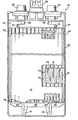
- a battery 10 comprises pasted grid, negative plates 12 and positive tubular plates 14 housed in a battery case 24.
- Each negative plate 12 is supported in the battery case 24 on stand-offs 18 by feet 20, of which only one is shown.
- a connecting lug 26 projects from the top of each negative plate, and a strap 28 electrically gangs together the negative plates 12 within a particular cell and connects them to the negative terminal 30.
- Each positive tubular plate 14 includes an electrically conductive cross member 32 and a connection lug 34.
- a strap 36 electrically gangs together the positive plates 14 disposed within the cell and connects them to the positive terminal 38.
- a row of electrically conductive spines 40 extend downwards from the cross member 32, and a porous, rigid sheath 44 envelopes each spine 40 to form a tube 16. Active material is packed into-the tubes 16.
- An electrically insulating cross member 46 is affixed to the tubes 16. Feet 48, of which only one is shown, support the plate 14 above the stand-off 18.
- the cross member 46 may be made from a suitable polymer such as polypropylene.
- a vent plug 52 permits the addition of water to the cell 10.
- the positive plate 14 is enveloped by a separator 50, folded or closed along its longitudinal sides and open at the top and bottom to form a sleeve, which is slipped over the positive plate 14.
- the sleeve 50 is sized to allow the lug 34 to protrude vertically from the enveloped plate 14 to make contact with the strap 36.
- a portion of the upper section of the sleeve 50 is attached to itself at location 58 by pinch welds (indicated in the drawing by a row of crosses) in the vicinity of the negative lug 26 and distally from the positive lug 34 to reduce mossing.
- the separator 50 is also registered against the cross member 46 at location 56 by a tack weld to prevent any upward movement of the sleeve 50, though other securing methods may of course be used.
- the sleeve welding operations may be conducted simultaneously or separately. They may be performed immediately after the sleeve 50 is positioned over the positive plate 14 by means of a heat sealing unit, a sonic or resistance welder or any other known welding device.
- a sleeve in accordance with the invention also alleviates problems, such as separator shifting, encountered during the handling of the plate prior to burning and nesting.
Landscapes
- Chemical & Material Sciences (AREA)
- Chemical Kinetics & Catalysis (AREA)
- Electrochemistry (AREA)
- General Chemical & Material Sciences (AREA)
- Engineering & Computer Science (AREA)
- Manufacturing & Machinery (AREA)
- Secondary Cells (AREA)
- Battery Electrode And Active Subsutance (AREA)
Applications Claiming Priority (2)
| Application Number | Priority Date | Filing Date | Title |
|---|---|---|---|
| US30153881A | 1981-09-14 | 1981-09-14 | |
| US301538 | 1981-09-14 |
Publications (2)
| Publication Number | Publication Date |
|---|---|
| EP0074831A2 true EP0074831A2 (fr) | 1983-03-23 |
| EP0074831A3 EP0074831A3 (fr) | 1983-09-28 |
Family
ID=23163812
Family Applications (1)
| Application Number | Title | Priority Date | Filing Date |
|---|---|---|---|
| EP82304798A Withdrawn EP0074831A3 (fr) | 1981-09-14 | 1982-09-13 | Accumulateurs électriques et plaques pour ceux-ci |
Country Status (1)
| Country | Link |
|---|---|
| EP (1) | EP0074831A3 (fr) |
Cited By (1)
| Publication number | Priority date | Publication date | Assignee | Title |
|---|---|---|---|---|
| EP0472232A3 (en) * | 1990-08-24 | 1993-03-31 | General Motors Corporation | Method of enveloping battery plates |
Family Cites Families (10)
| Publication number | Priority date | Publication date | Assignee | Title |
|---|---|---|---|---|
| BE484114A (fr) * | 1947-06-09 | |||
| US3092438A (en) * | 1959-11-09 | 1963-06-04 | Gen Motors Corp | Production of filled polyolefin molding compound and the molding of articles therefrom |
| US3253954A (en) * | 1963-08-13 | 1966-05-31 | Gould National Batteries Inc | Retaining member for storage battery electrodes |
| GB1260891A (en) * | 1968-09-06 | 1972-01-19 | Ezra Vittorio Picciotto | Separator of synthetic fibre for lead-acid secondary batteries |
| DE1964859A1 (de) * | 1969-12-24 | 1971-07-01 | Varta Ag | Elektrode fuer galvanische Elemente |
| DE2048769A1 (de) * | 1970-10-05 | 1972-04-06 | Metzler O | Verfahren zur Herstellung eines Bleiakkumulators |
| FR2266318A1 (en) * | 1974-03-26 | 1975-10-24 | Europ Accumulateurs | Electric accumulator cell - has sheathed positive plate held against active material by grooved separator |
| DE2836416A1 (de) * | 1978-08-19 | 1980-03-06 | Bosch Gmbh Robert | Elektrodenplatte fuer bleiakkumulatoren |
| US4327163A (en) * | 1980-11-14 | 1982-04-27 | General Motors Corporation | Half-envelope separator assemblies on individual plates |
| JPS57136769A (en) * | 1981-02-18 | 1982-08-23 | Shin Kobe Electric Mach Co Ltd | Manufacture of plate body for lead battery |
-
1982
- 1982-09-13 EP EP82304798A patent/EP0074831A3/fr not_active Withdrawn
Cited By (1)
| Publication number | Priority date | Publication date | Assignee | Title |
|---|---|---|---|---|
| EP0472232A3 (en) * | 1990-08-24 | 1993-03-31 | General Motors Corporation | Method of enveloping battery plates |
Also Published As
| Publication number | Publication date |
|---|---|
| EP0074831A3 (fr) | 1983-09-28 |
Similar Documents
| Publication | Publication Date | Title |
|---|---|---|
| US5582936A (en) | Lead-acid batteries with optimum current collection at grid lugs | |
| CA1163675A (fr) | Accumulateur au plomb-acide de longue duree utile dans des conditions repetitives de decharge et de rechargement rapides | |
| WO1998005081A1 (fr) | Accumulateur bipolaire au plomb perfectionne | |
| JPH07105929A (ja) | 鉛蓄電池 | |
| JP4062388B2 (ja) | アルカリ蓄電池 | |
| CN2239079Y (zh) | 带排气阀的高性能密封铅酸蓄电池 | |
| JPH0629016A (ja) | 新規な耳および末端カバー組立体を有する新規な密封鉛電池 | |
| JP2009104914A (ja) | 鉛蓄電池 | |
| US6174619B1 (en) | Structure for positioning electrode plates in a battery casing | |
| JP2004014283A (ja) | 制御弁式鉛蓄電池 | |
| JPH08287944A (ja) | 鉛蓄電池 | |
| US5001022A (en) | Lead-acid storage battery and related method of construction | |
| AU669464B2 (en) | Galvanic cells and batteries having a novel grid, strap and intercell weld arrangement | |
| JP3524744B2 (ja) | 密閉型アルカリ蓄電池 | |
| KR870000967B1 (ko) | 무 보수 밀폐형 납산-전지 | |
| US12567626B1 (en) | Zinc bromine cell having enclosed electrodes | |
| JPH0628169B2 (ja) | 密閉形鉛蓄電池 | |
| JPH0869811A (ja) | 鉛蓄電池 | |
| KR200319220Y1 (ko) | 등 부표용 축전지 | |
| KR200423897Y1 (ko) | 등 부표용 축전지 | |
| KR101206251B1 (ko) | 전해질 자가 순환 기능을 갖는 축전지 | |
| Burrows et al. | Low maintenance lead-acid batteries for energy storage | |
| EP0143666B1 (fr) | Pile au plomb-acide à recombinaison | |
| JPH0927318A (ja) | 鉛蓄電池 | |
| JPS58165245A (ja) | 鉛蓄電池 |
Legal Events
| Date | Code | Title | Description |
|---|---|---|---|
| PUAI | Public reference made under article 153(3) epc to a published international application that has entered the european phase |
Free format text: ORIGINAL CODE: 0009012 |
|
| AK | Designated contracting states |
Designated state(s): DE FR GB |
|
| PUAL | Search report despatched |
Free format text: ORIGINAL CODE: 0009013 |
|
| STAA | Information on the status of an ep patent application or granted ep patent |
Free format text: STATUS: THE APPLICATION HAS BEEN WITHDRAWN |
|
| AK | Designated contracting states |
Designated state(s): DE FR GB |
|
| 18W | Application withdrawn |
Withdrawal date: 19830906 |
|
| RIN1 | Information on inventor provided before grant (corrected) |
Inventor name: VINKLER, JOHN F. |