EP0074881A1 - Verfahren und Vorrichtung zur automatischen und kontinuierlichen Messung von Scherkräften an Formsand in einer Einrichtung zur Herstellung von Formen - Google Patents
Verfahren und Vorrichtung zur automatischen und kontinuierlichen Messung von Scherkräften an Formsand in einer Einrichtung zur Herstellung von Formen Download PDFInfo
- Publication number
- EP0074881A1 EP0074881A1 EP82401617A EP82401617A EP0074881A1 EP 0074881 A1 EP0074881 A1 EP 0074881A1 EP 82401617 A EP82401617 A EP 82401617A EP 82401617 A EP82401617 A EP 82401617A EP 0074881 A1 EP0074881 A1 EP 0074881A1
- Authority
- EP
- European Patent Office
- Prior art keywords
- sand
- orifice
- measuring
- measuring ring
- strain gauges
- Prior art date
- Legal status (The legal status is an assumption and is not a legal conclusion. Google has not performed a legal analysis and makes no representation as to the accuracy of the status listed.)
- Granted
Links
- 239000004576 sand Substances 0.000 title claims abstract description 43
- 238000000034 method Methods 0.000 title claims abstract description 18
- 238000005259 measurement Methods 0.000 title claims abstract description 17
- 238000009434 installation Methods 0.000 title abstract 2
- 238000004519 manufacturing process Methods 0.000 title description 2
- 239000003795 chemical substances by application Substances 0.000 claims abstract description 5
- 230000008929 regeneration Effects 0.000 claims abstract description 5
- 238000011069 regeneration method Methods 0.000 claims abstract description 5
- 238000005056 compaction Methods 0.000 claims description 7
- 238000003801 milling Methods 0.000 claims description 5
- 238000007664 blowing Methods 0.000 claims description 2
- 230000008030 elimination Effects 0.000 claims 1
- 238000003379 elimination reaction Methods 0.000 claims 1
- 238000000465 moulding Methods 0.000 abstract description 7
- 230000003252 repetitive effect Effects 0.000 abstract description 3
- 238000010008 shearing Methods 0.000 abstract 1
- VYPSYNLAJGMNEJ-UHFFFAOYSA-N Silicium dioxide Chemical compound O=[Si]=O VYPSYNLAJGMNEJ-UHFFFAOYSA-N 0.000 description 32
- 238000000605 extraction Methods 0.000 description 4
- 239000004927 clay Substances 0.000 description 3
- 229910000831 Steel Inorganic materials 0.000 description 2
- 239000000440 bentonite Substances 0.000 description 2
- 229910000278 bentonite Inorganic materials 0.000 description 2
- SVPXDRXYRYOSEX-UHFFFAOYSA-N bentoquatam Chemical compound O.O=[Si]=O.O=[Al]O[Al]=O SVPXDRXYRYOSEX-UHFFFAOYSA-N 0.000 description 2
- 230000000694 effects Effects 0.000 description 2
- 239000000463 material Substances 0.000 description 2
- 239000002184 metal Substances 0.000 description 2
- 239000003110 molding sand Substances 0.000 description 2
- 238000000926 separation method Methods 0.000 description 2
- 239000010959 steel Substances 0.000 description 2
- 238000012360 testing method Methods 0.000 description 2
- OKTJSMMVPCPJKN-UHFFFAOYSA-N Carbon Chemical compound [C] OKTJSMMVPCPJKN-UHFFFAOYSA-N 0.000 description 1
- 238000005266 casting Methods 0.000 description 1
- 230000008602 contraction Effects 0.000 description 1
- 230000008094 contradictory effect Effects 0.000 description 1
- 238000001816 cooling Methods 0.000 description 1
- 238000012937 correction Methods 0.000 description 1
- 238000011161 development Methods 0.000 description 1
- 230000018109 developmental process Effects 0.000 description 1
- 239000006185 dispersion Substances 0.000 description 1
- 239000012530 fluid Substances 0.000 description 1
- 230000002706 hydrostatic effect Effects 0.000 description 1
- 238000007373 indentation Methods 0.000 description 1
- 238000004898 kneading Methods 0.000 description 1
- 238000005058 metal casting Methods 0.000 description 1
- VUZPPFZMUPKLLV-UHFFFAOYSA-N methane;hydrate Chemical compound C.O VUZPPFZMUPKLLV-UHFFFAOYSA-N 0.000 description 1
- 239000000203 mixture Substances 0.000 description 1
- 230000003071 parasitic effect Effects 0.000 description 1
- 238000003825 pressing Methods 0.000 description 1
- 238000003908 quality control method Methods 0.000 description 1
- 230000035939 shock Effects 0.000 description 1
- 239000000377 silicon dioxide Substances 0.000 description 1
- 239000007787 solid Substances 0.000 description 1
- 238000007711 solidification Methods 0.000 description 1
- 230000008023 solidification Effects 0.000 description 1
- 238000003860 storage Methods 0.000 description 1
- 239000010409 thin film Substances 0.000 description 1
- XLYOFNOQVPJJNP-UHFFFAOYSA-N water Substances O XLYOFNOQVPJJNP-UHFFFAOYSA-N 0.000 description 1
Images

Classifications
-
- B—PERFORMING OPERATIONS; TRANSPORTING
- B22—CASTING; POWDER METALLURGY
- B22C—FOUNDRY MOULDING
- B22C5/00—Machines or devices specially designed for dressing or handling the mould material so far as specially adapted for that purpose
-
- G—PHYSICS
- G01—MEASURING; TESTING
- G01N—INVESTIGATING OR ANALYSING MATERIALS BY DETERMINING THEIR CHEMICAL OR PHYSICAL PROPERTIES
- G01N3/00—Investigating strength properties of solid materials by application of mechanical stress
- G01N3/24—Investigating strength properties of solid materials by application of mechanical stress by applying steady shearing forces
-
- G—PHYSICS
- G01—MEASURING; TESTING
- G01N—INVESTIGATING OR ANALYSING MATERIALS BY DETERMINING THEIR CHEMICAL OR PHYSICAL PROPERTIES
- G01N2203/00—Investigating strength properties of solid materials by application of mechanical stress
- G01N2203/02—Details not specific for a particular testing method
- G01N2203/0202—Control of the test
- G01N2203/0206—Means for supplying or positioning specimens or exchangeable parts of the machine such as indenters...
-
- G—PHYSICS
- G01—MEASURING; TESTING
- G01N—INVESTIGATING OR ANALYSING MATERIALS BY DETERMINING THEIR CHEMICAL OR PHYSICAL PROPERTIES
- G01N2203/00—Investigating strength properties of solid materials by application of mechanical stress
- G01N2203/02—Details not specific for a particular testing method
- G01N2203/0202—Control of the test
- G01N2203/0212—Theories, calculations
- G01N2203/0218—Calculations based on experimental data
-
- G—PHYSICS
- G01—MEASURING; TESTING
- G01N—INVESTIGATING OR ANALYSING MATERIALS BY DETERMINING THEIR CHEMICAL OR PHYSICAL PROPERTIES
- G01N2203/00—Investigating strength properties of solid materials by application of mechanical stress
- G01N2203/02—Details not specific for a particular testing method
- G01N2203/022—Environment of the test
- G01N2203/0248—Tests "on-line" during fabrication
-
- G—PHYSICS
- G01—MEASURING; TESTING
- G01N—INVESTIGATING OR ANALYSING MATERIALS BY DETERMINING THEIR CHEMICAL OR PHYSICAL PROPERTIES
- G01N2203/00—Investigating strength properties of solid materials by application of mechanical stress
- G01N2203/02—Details not specific for a particular testing method
- G01N2203/026—Specifications of the specimen
- G01N2203/0284—Bulk material, e.g. powders
Definitions
- a well-known method consists in making substantially parallelepipedic clods by compressing sand in a horizontal press between a front opening model plate and a rear model plate exerting the thrust, these clods being assembled as they come out. of the press in a continuous horizontal column reconstituting a complete molding imprint at each junction between clods, which subsequently allows a metal casting at a rate repeated in these various indentations, the clods continuing to advance during the cooling of the parts until at an end station where the sanding takes place. At each operating cycle the sand is thrown vertically at high speed between the closed front plate and the back rear plate before pressurizing.
- the sand used is so-called "green" molding sand, a material composed of silica grains mixed with a clay called bentonite, carbon powder and water.
- green molding sand a material composed of silica grains mixed with a clay called bentonite, carbon powder and water.
- each solid grain is coated with a thin film of clay suitably hydrated in order to give the cohesion forces necessary under the effect of tightening at high pressure, generally of the order of 10 kg / cm 2 .
- this sand must meet contradictory requirements, since it must be sufficiently fluid to be able to be compacted with ease around all the details of the model plates and at the same time to be sufficiently rigid after compaction not to collapse or deform after separation of the model plates. On the other hand, it must have a good cohesion, in particular a resistance sufficient shear strength to withstand the molding stresses, such as the hydrostatic pressure of the molten metal, thermal shock at the time of casting and the stresses due to the contraction of the metal. during solidification, but at the same time be able to break without too much difficulty during the sanding for the extraction of parts.
- the usual methods of quality control of the sand consist in taking a sample of uncompacted sand, that is to say taken in the hopper of the machine, to make in an external laboratory apparatus a cylindrical test tube (5cm x 5cm ) tightened to 10 kg / cm 2 and to shear this test piece on a special machine.
- the regenerations are modulated into agglomerating agents, or bentonite clay, according to the fluctuations observed with respect to the fixed limits.
- control relates only to the quality of the sand proper before compaction, and not to the actual conditions in which it is found inside the clod.
- the object of the invention is to eliminate the above drawbacks by providing a means and a device for measuring, as automatically and as quickly as not only the quality of the sand itself, but payment for the quality of its compaction inside each clod.
- the invention consists in fixing on one of the model plates, preferably on the rear model plate, a measurement ring comprising a central hole, preferably a bore whose axis is parallel to the model plate and preferably parallel to the direction.
- a measurement ring comprising a central hole, preferably a bore whose axis is parallel to the model plate and preferably parallel to the direction.
- sand blowing that is to say generally vertical, with a thinning on its two lateral edges comprising a strain gauge electrically connected through the support and the model plate to an external measuring device, this ring being between two parallel planes or preferably in slight draft in the direction of demoulding, so that when the model plate is extracted from the root ball, this ring produces a double shear of the sand cylinder contained in its bore and which was compacted by the normal process of making the root ball under normal conditions prevailing at the heart of it.
- the signals provided by the strain gauges are exploited electronically to derive the shear strength therefrom, and processed by
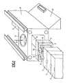
- the model plate 2 comprises, in the usual manner, bankruptcies 8 corresponding to the shape of the parts to be molded. at the joint plane (the forms beyond this plane being carried by the other model plate not shown) and also a projection 9 intended to reserve the tap hole and the pour channel (direct or at source).
- this plate model 2 in a suitable place between these various projections 8 and 9, and preferably in the heart of the root ball, a measuring ring 10 shown in detail in figs 2 and 3 .
- This ring advantageously has the shape of a bearing to allow its convenient attachment to the model plate 2 using screws passing through the holes 11 of its sole. It essentially comprises a bore 12, for example 50 mm, whose axis is parallel to direction 6, that is to say generally vertical.
- the body of this ring in wear-resistant steel, preferably in 35CD4T4 steel, is limited between two planes 13 of direction substantially perpendicular to the model plate 2, but preferably in slight draft in the direction of demolding as shown in Figure 3.
- Two lateral millings 14, for example cylindrical as shown in the figures, have the effect of reducing the section of the lateral branches of the ring, which work in the direction of extraction of the model plate, to a small section 13, for example of the order of 1.5 mm thick.
- strain gauges not shown which are coupled in a Wheatstone bridge in the usual way with thermal compensation gauges, and electrically connected by cables passing through the ring 10 through holes 16, and the model plate 2 as well as the plate 3 through suitable holes to join the measuring device and 17 by flexible connections not shown.
- the sand also fills the interior of the bore 12 of the ring 10 is there to the pressure there.
- the ring drives the sand cylinder which it contains and separates it from the rest of the clod by a double shear according to the two planes 13.
- the unraveling these two planes facilitates this separation by avoiding introducing parasitic stresses which could distort the measurement.
- the two millings 14 are preferably filled with a material intended to protect the strain gauges and at the same time avoid any undercut.
- the shear strength of the sand cylinder according to the two shear planes 13 is therefore measured exactly by the sum of the tensions of the two parts 15, measured by the strain gauges, relative to the sum of the two sections of the sand cylinder.
- the negative impression provided by the ring in the root ball is unimportant in the following since it does not communicate with the other impressions nor with the tap hole.
- the sand cylinder remaining in the bore 12 of the ring is driven out in the following molding by the projection of blown sand in direction 6, the sand thus driven down. by the pressure being brought back into cohesion with the rest of the sand during the following pressing cycle.
- the invention thus allows, at each cycle of making a clod 7, to have an accurate and instantaneous measurement of the shear strength of the sand cylinder under the compaction pressure actually present in the clod.
- the method according to the invention also makes it possible, by knowing the properties of the sand used, to also control the quality of the compaction at the heart of the mold and its development, and to adjust the pressure supplied by the press accordingly. It also makes it possible to individually check that each mold actually receives the correct pressure and instantly report any failure.
- the invention thus makes it possible to avoid the use of a controller and in addition to provide instantaneous indication of the various adjustments to be made, manually or automatically, with a view to perfect manufacturing consistency enabling parts to be obtained quality foundry with a low scrap percentage
Landscapes
- Physics & Mathematics (AREA)
- Health & Medical Sciences (AREA)
- Life Sciences & Earth Sciences (AREA)
- Chemical & Material Sciences (AREA)
- Analytical Chemistry (AREA)
- Biochemistry (AREA)
- General Health & Medical Sciences (AREA)
- General Physics & Mathematics (AREA)
- Immunology (AREA)
- Pathology (AREA)
- Engineering & Computer Science (AREA)
- Mechanical Engineering (AREA)
- Investigating Strength Of Materials By Application Of Mechanical Stress (AREA)
- Mold Materials And Core Materials (AREA)
- Measurement Of Resistance Or Impedance (AREA)
- Measuring Instrument Details And Bridges, And Automatic Balancing Devices (AREA)
Applications Claiming Priority (2)
| Application Number | Priority Date | Filing Date | Title |
|---|---|---|---|
| FR8117244A FR2512954A1 (fr) | 1981-09-11 | 1981-09-11 | Procede et dispositif de mesure automatique et en continu de la resistance au cisaillement du sable a vert utilise dans les installations de moulage modernes |
| FR8117244 | 1981-09-11 |
Publications (2)
| Publication Number | Publication Date |
|---|---|
| EP0074881A1 true EP0074881A1 (de) | 1983-03-23 |
| EP0074881B1 EP0074881B1 (de) | 1985-04-03 |
Family
ID=9262080
Family Applications (1)
| Application Number | Title | Priority Date | Filing Date |
|---|---|---|---|
| EP82401617A Expired EP0074881B1 (de) | 1981-09-11 | 1982-09-02 | Verfahren und Vorrichtung zur automatischen und kontinuierlichen Messung von Scherkräften an Formsand in einer Einrichtung zur Herstellung von Formen |
Country Status (7)
| Country | Link |
|---|---|
| US (1) | US4442884A (de) |
| EP (1) | EP0074881B1 (de) |
| JP (1) | JPS5858435A (de) |
| DE (1) | DE3262885D1 (de) |
| DK (1) | DK395082A (de) |
| FR (1) | FR2512954A1 (de) |
| NO (1) | NO823032L (de) |
Cited By (2)
| Publication number | Priority date | Publication date | Assignee | Title |
|---|---|---|---|---|
| EP0715161A1 (de) * | 1994-12-02 | 1996-06-05 | Sintokogio, Ltd. | Verfahren und Vorrichtung zum Gewinnen von Daten über das Spannungs-Dehnungs-Verhältnis von Prüflingen aus grünem Sand für Gussformen |
| CN104931338A (zh) * | 2015-06-04 | 2015-09-23 | 廊坊市阳光建设工程质量检测有限公司 | 任意角度回弹测试砼试块的固定装置及其制作和使用方法 |
Families Citing this family (2)
| Publication number | Priority date | Publication date | Assignee | Title |
|---|---|---|---|---|
| US5461933A (en) * | 1994-02-04 | 1995-10-31 | Acutus Industries, Inc. | Shear web load cell having thermal compensation |
| USH1769H (en) * | 1995-06-06 | 1999-01-05 | The United States Of America As Represented By The Secretary Of The Air Force | Optimized recursive foundry tooling fabrication method |
Citations (4)
| Publication number | Priority date | Publication date | Assignee | Title |
|---|---|---|---|---|
| US3335787A (en) * | 1964-08-05 | 1967-08-15 | Dietert Co Harry W | Automatic mold testing apparatus |
| US3373977A (en) * | 1966-06-10 | 1968-03-19 | Dietert Co Harry W | Granular material conditioning apparatus |
| FR92286E (fr) * | 1963-02-18 | 1968-10-18 | Dietert Co Harry W | Dispositif pour la pesée et le transport de matière en vrac, qui est fournie en sacs |
| DE2937473B1 (de) * | 1978-08-28 | 1981-02-05 | Klaus Dipl-Ing Ritzinger | Vorrichtung zum Messen von Scherkraeften |
Family Cites Families (1)
| Publication number | Priority date | Publication date | Assignee | Title |
|---|---|---|---|---|
| FR1389730A (fr) * | 1963-02-18 | 1965-02-19 | Dietert Co Harry W | Dispositif pour la pesée et le transport de matière en vrac, qui est fournie en sacs |
-
1981
- 1981-09-11 FR FR8117244A patent/FR2512954A1/fr active Granted
-
1982
- 1982-09-02 DE DE8282401617T patent/DE3262885D1/de not_active Expired
- 1982-09-02 EP EP82401617A patent/EP0074881B1/de not_active Expired
- 1982-09-03 DK DK395082A patent/DK395082A/da not_active Application Discontinuation
- 1982-09-07 JP JP57154729A patent/JPS5858435A/ja active Pending
- 1982-09-08 NO NO823032A patent/NO823032L/no unknown
- 1982-09-13 US US06/416,967 patent/US4442884A/en not_active Expired - Fee Related
Patent Citations (4)
| Publication number | Priority date | Publication date | Assignee | Title |
|---|---|---|---|---|
| FR92286E (fr) * | 1963-02-18 | 1968-10-18 | Dietert Co Harry W | Dispositif pour la pesée et le transport de matière en vrac, qui est fournie en sacs |
| US3335787A (en) * | 1964-08-05 | 1967-08-15 | Dietert Co Harry W | Automatic mold testing apparatus |
| US3373977A (en) * | 1966-06-10 | 1968-03-19 | Dietert Co Harry W | Granular material conditioning apparatus |
| DE2937473B1 (de) * | 1978-08-28 | 1981-02-05 | Klaus Dipl-Ing Ritzinger | Vorrichtung zum Messen von Scherkraeften |
Cited By (2)
| Publication number | Priority date | Publication date | Assignee | Title |
|---|---|---|---|---|
| EP0715161A1 (de) * | 1994-12-02 | 1996-06-05 | Sintokogio, Ltd. | Verfahren und Vorrichtung zum Gewinnen von Daten über das Spannungs-Dehnungs-Verhältnis von Prüflingen aus grünem Sand für Gussformen |
| CN104931338A (zh) * | 2015-06-04 | 2015-09-23 | 廊坊市阳光建设工程质量检测有限公司 | 任意角度回弹测试砼试块的固定装置及其制作和使用方法 |
Also Published As
| Publication number | Publication date |
|---|---|
| US4442884A (en) | 1984-04-17 |
| FR2512954B1 (de) | 1984-01-20 |
| DK395082A (da) | 1983-03-12 |
| JPS5858435A (ja) | 1983-04-07 |
| NO823032L (no) | 1983-03-14 |
| DE3262885D1 (en) | 1985-05-09 |
| FR2512954A1 (fr) | 1983-03-18 |
| EP0074881B1 (de) | 1985-04-03 |
Similar Documents
| Publication | Publication Date | Title |
|---|---|---|
| EP0802840B1 (de) | Verfahren zum einspritzen von flüssigmetall in einen formhohlräum | |
| FR2541769A1 (fr) | Procede et dispositif pour la mesure de proprietes d'une matiere a mouler et utilisation dudit dispositif | |
| EP0074881B1 (de) | Verfahren und Vorrichtung zur automatischen und kontinuierlichen Messung von Scherkräften an Formsand in einer Einrichtung zur Herstellung von Formen | |
| CH624032A5 (de) | ||
| FR2501552A1 (fr) | Agencement pour le reglage de l'inclinaison des petits cotes d'une coquille a brames | |
| GB2087100A (en) | Continuous strip casting | |
| SE430209B (sv) | Sett vid framstellning av en pelare for en rotfylld, preparerad tand samt anordning for genomforande av detta sett | |
| FR2721844A1 (fr) | Procede et dispositif de coulee continue de produits metalliques minces entre cylinders | |
| DE4444123C2 (de) | Druckgießverfahren und Druckgießvorrichtung | |
| CH644288A5 (fr) | Procede et machine de coulee continue de metal. | |
| EP0463910B1 (de) | Verfahren und Vorrichtung zur Durchführung flüssigen Metalls in eine Sandgiessform mittels Niederdruck | |
| EP0809555B1 (de) | Verfahren und vorrichtung zur trennmittelregelung in einer druckgiessmaschine | |
| RU2167740C1 (ru) | Способ активной подпитки отливок в литейных формах, устройство для подачи давления и система подачи давления для активной подпитки отливок | |
| EP0564316B1 (de) | Verfahren zum Stranggiessen | |
| US2864125A (en) | Press for dental investment material | |
| CA1086961A (en) | Method and apparatus for introducing an additive material into a molten metal at a variable rate | |
| NO180110B (no) | Fremgangsmåte og anordning for å styre mengdeströmmen av smeltet material som stöpes fra et basseng for mottak og oppbevaring av et smeltet material | |
| CN115502368B (zh) | 一种自动挤压铸造机及其控制方法 | |
| EP0055947B1 (de) | Verfahren und Vorrichtung zum Automatisieren eines Niederdruck-Giessvorganges | |
| DE60212877T2 (de) | Vorrichtung zur herstellung von metallgussteilen | |
| JPH10109339A (ja) | 射出成形機の成形条件設定方法 | |
| JPH0531564A (ja) | 局部スクイズ鋳造におけるスクイズピンの加圧タイミング制御方法 | |
| CA1237268A (fr) | Dispositif de support de produit coule en sortie d'une lingotiere pour coulee continue et procede de reglage de la position du support | |
| CN212964152U (zh) | 一种炭黑成品用的取样装置 | |
| EP1525933A2 (de) | Verfahren und Vorrichtung zur Herstellung von Bauteilen aus einer Metalllegierung |
Legal Events
| Date | Code | Title | Description |
|---|---|---|---|
| PUAI | Public reference made under article 153(3) epc to a published international application that has entered the european phase |
Free format text: ORIGINAL CODE: 0009012 |
|
| 17P | Request for examination filed |
Effective date: 19820906 |
|
| AK | Designated contracting states |
Designated state(s): CH DE LI SE |
|
| GRAA | (expected) grant |
Free format text: ORIGINAL CODE: 0009210 |
|
| AK | Designated contracting states |
Designated state(s): CH DE LI SE |
|
| REF | Corresponds to: |
Ref document number: 3262885 Country of ref document: DE Date of ref document: 19850509 |
|
| PLBE | No opposition filed within time limit |
Free format text: ORIGINAL CODE: 0009261 |
|
| STAA | Information on the status of an ep patent application or granted ep patent |
Free format text: STATUS: NO OPPOSITION FILED WITHIN TIME LIMIT |
|
| 26N | No opposition filed | ||
| PGFP | Annual fee paid to national office [announced via postgrant information from national office to epo] |
Ref country code: DE Payment date: 19890530 Year of fee payment: 8 |
|
| PGFP | Annual fee paid to national office [announced via postgrant information from national office to epo] |
Ref country code: SE Payment date: 19890821 Year of fee payment: 8 Ref country code: CH Payment date: 19890821 Year of fee payment: 8 |
|
| PG25 | Lapsed in a contracting state [announced via postgrant information from national office to epo] |
Ref country code: SE Effective date: 19900903 |
|
| PG25 | Lapsed in a contracting state [announced via postgrant information from national office to epo] |
Ref country code: LI Effective date: 19900930 Ref country code: CH Effective date: 19900930 |
|
| REG | Reference to a national code |
Ref country code: CH Ref legal event code: PL |
|
| PG25 | Lapsed in a contracting state [announced via postgrant information from national office to epo] |
Ref country code: DE Effective date: 19910601 |
|
| EUG | Se: european patent has lapsed |
Ref document number: 82401617.4 Effective date: 19910527 |