EP0074883B1 - Vorrichtung zur Übertragung geradliniger Bewegungen mittels Riemenscheiben und Treibriemen - Google Patents
Vorrichtung zur Übertragung geradliniger Bewegungen mittels Riemenscheiben und Treibriemen Download PDFInfo
- Publication number
- EP0074883B1 EP0074883B1 EP82401619A EP82401619A EP0074883B1 EP 0074883 B1 EP0074883 B1 EP 0074883B1 EP 82401619 A EP82401619 A EP 82401619A EP 82401619 A EP82401619 A EP 82401619A EP 0074883 B1 EP0074883 B1 EP 0074883B1
- Authority
- EP
- European Patent Office
- Prior art keywords
- belts
- pulley
- movable member
- fixed
- support
- Prior art date
- Legal status (The legal status is an assumption and is not a legal conclusion. Google has not performed a legal analysis and makes no representation as to the accuracy of the status listed.)
- Expired
Links
Images

Classifications
-
- B—PERFORMING OPERATIONS; TRANSPORTING
- B25—HAND TOOLS; PORTABLE POWER-DRIVEN TOOLS; MANIPULATORS
- B25J—MANIPULATORS; CHAMBERS PROVIDED WITH MANIPULATION DEVICES
- B25J9/00—Program-controlled manipulators
- B25J9/02—Program-controlled manipulators characterised by movement of the arms, e.g. cartesian coordinate type
- B25J9/023—Cartesian coordinate type
-
- F—MECHANICAL ENGINEERING; LIGHTING; HEATING; WEAPONS; BLASTING
- F16—ENGINEERING ELEMENTS AND UNITS; GENERAL MEASURES FOR PRODUCING AND MAINTAINING EFFECTIVE FUNCTIONING OF MACHINES OR INSTALLATIONS; THERMAL INSULATION IN GENERAL
- F16H—GEARING
- F16H19/00—Gearings comprising essentially only toothed gears or friction members and not capable of conveying indefinitely-continuing rotary motion
- F16H19/02—Gearings comprising essentially only toothed gears or friction members and not capable of conveying indefinitely-continuing rotary motion for interconverting rotary or oscillating motion and reciprocating motion
- F16H19/06—Gearings comprising essentially only toothed gears or friction members and not capable of conveying indefinitely-continuing rotary motion for interconverting rotary or oscillating motion and reciprocating motion comprising flexible members, e.g. an endless flexible member
- F16H19/0622—Gearings comprising essentially only toothed gears or friction members and not capable of conveying indefinitely-continuing rotary motion for interconverting rotary or oscillating motion and reciprocating motion comprising flexible members, e.g. an endless flexible member for converting reciprocating movement into oscillating movement and vice versa, the reciprocating movement is perpendicular to the axis of oscillation
-
- F—MECHANICAL ENGINEERING; LIGHTING; HEATING; WEAPONS; BLASTING
- F16—ENGINEERING ELEMENTS AND UNITS; GENERAL MEASURES FOR PRODUCING AND MAINTAINING EFFECTIVE FUNCTIONING OF MACHINES OR INSTALLATIONS; THERMAL INSULATION IN GENERAL
- F16H—GEARING
- F16H19/00—Gearings comprising essentially only toothed gears or friction members and not capable of conveying indefinitely-continuing rotary motion
- F16H19/02—Gearings comprising essentially only toothed gears or friction members and not capable of conveying indefinitely-continuing rotary motion for interconverting rotary or oscillating motion and reciprocating motion
- F16H19/06—Gearings comprising essentially only toothed gears or friction members and not capable of conveying indefinitely-continuing rotary motion for interconverting rotary or oscillating motion and reciprocating motion comprising flexible members, e.g. an endless flexible member
- F16H19/0672—Gearings comprising essentially only toothed gears or friction members and not capable of conveying indefinitely-continuing rotary motion for interconverting rotary or oscillating motion and reciprocating motion comprising flexible members, e.g. an endless flexible member characterised by means for tensioning the flexible member
-
- F—MECHANICAL ENGINEERING; LIGHTING; HEATING; WEAPONS; BLASTING
- F16—ENGINEERING ELEMENTS AND UNITS; GENERAL MEASURES FOR PRODUCING AND MAINTAINING EFFECTIVE FUNCTIONING OF MACHINES OR INSTALLATIONS; THERMAL INSULATION IN GENERAL
- F16H—GEARING
- F16H19/00—Gearings comprising essentially only toothed gears or friction members and not capable of conveying indefinitely-continuing rotary motion
- F16H19/02—Gearings comprising essentially only toothed gears or friction members and not capable of conveying indefinitely-continuing rotary motion for interconverting rotary or oscillating motion and reciprocating motion
- F16H19/06—Gearings comprising essentially only toothed gears or friction members and not capable of conveying indefinitely-continuing rotary motion for interconverting rotary or oscillating motion and reciprocating motion comprising flexible members, e.g. an endless flexible member
- F16H2019/0681—Gearings comprising essentially only toothed gears or friction members and not capable of conveying indefinitely-continuing rotary motion for interconverting rotary or oscillating motion and reciprocating motion comprising flexible members, e.g. an endless flexible member the flexible member forming a closed loop
- F16H2019/0686—Gearings comprising essentially only toothed gears or friction members and not capable of conveying indefinitely-continuing rotary motion for interconverting rotary or oscillating motion and reciprocating motion comprising flexible members, e.g. an endless flexible member the flexible member forming a closed loop the flexible member being directly driven by a pulley or chain wheel
-
- F—MECHANICAL ENGINEERING; LIGHTING; HEATING; WEAPONS; BLASTING
- F16—ENGINEERING ELEMENTS AND UNITS; GENERAL MEASURES FOR PRODUCING AND MAINTAINING EFFECTIVE FUNCTIONING OF MACHINES OR INSTALLATIONS; THERMAL INSULATION IN GENERAL
- F16H—GEARING
- F16H19/00—Gearings comprising essentially only toothed gears or friction members and not capable of conveying indefinitely-continuing rotary motion
- F16H19/02—Gearings comprising essentially only toothed gears or friction members and not capable of conveying indefinitely-continuing rotary motion for interconverting rotary or oscillating motion and reciprocating motion
- F16H19/06—Gearings comprising essentially only toothed gears or friction members and not capable of conveying indefinitely-continuing rotary motion for interconverting rotary or oscillating motion and reciprocating motion comprising flexible members, e.g. an endless flexible member
- F16H2019/069—Gearings comprising essentially only toothed gears or friction members and not capable of conveying indefinitely-continuing rotary motion for interconverting rotary or oscillating motion and reciprocating motion comprising flexible members, e.g. an endless flexible member with means for generating two superposed movements, e.g. for driving a X-Y table
-
- Y—GENERAL TAGGING OF NEW TECHNOLOGICAL DEVELOPMENTS; GENERAL TAGGING OF CROSS-SECTIONAL TECHNOLOGIES SPANNING OVER SEVERAL SECTIONS OF THE IPC; TECHNICAL SUBJECTS COVERED BY FORMER USPC CROSS-REFERENCE ART COLLECTIONS [XRACs] AND DIGESTS
- Y10—TECHNICAL SUBJECTS COVERED BY FORMER USPC
- Y10T—TECHNICAL SUBJECTS COVERED BY FORMER US CLASSIFICATION
- Y10T74/00—Machine element or mechanism
- Y10T74/18—Mechanical movements
- Y10T74/18568—Reciprocating or oscillating to or from alternating rotary
- Y10T74/18832—Reciprocating or oscillating to or from alternating rotary including flexible drive connector [e.g., belt, chain, strand, etc.]
-
- Y—GENERAL TAGGING OF NEW TECHNOLOGICAL DEVELOPMENTS; GENERAL TAGGING OF CROSS-SECTIONAL TECHNOLOGIES SPANNING OVER SEVERAL SECTIONS OF THE IPC; TECHNICAL SUBJECTS COVERED BY FORMER USPC CROSS-REFERENCE ART COLLECTIONS [XRACs] AND DIGESTS
- Y10—TECHNICAL SUBJECTS COVERED BY FORMER USPC
- Y10T—TECHNICAL SUBJECTS COVERED BY FORMER US CLASSIFICATION
- Y10T74/00—Machine element or mechanism
- Y10T74/18—Mechanical movements
- Y10T74/18568—Reciprocating or oscillating to or from alternating rotary
- Y10T74/18832—Reciprocating or oscillating to or from alternating rotary including flexible drive connector [e.g., belt, chain, strand, etc.]
- Y10T74/18848—Reciprocating or oscillating to or from alternating rotary including flexible drive connector [e.g., belt, chain, strand, etc.] with pulley
-
- Y—GENERAL TAGGING OF NEW TECHNOLOGICAL DEVELOPMENTS; GENERAL TAGGING OF CROSS-SECTIONAL TECHNOLOGIES SPANNING OVER SEVERAL SECTIONS OF THE IPC; TECHNICAL SUBJECTS COVERED BY FORMER USPC CROSS-REFERENCE ART COLLECTIONS [XRACs] AND DIGESTS
- Y10—TECHNICAL SUBJECTS COVERED BY FORMER USPC
- Y10T—TECHNICAL SUBJECTS COVERED BY FORMER US CLASSIFICATION
- Y10T74/00—Machine element or mechanism
- Y10T74/20—Control lever and linkage systems
- Y10T74/20012—Multiple controlled elements
- Y10T74/20201—Control moves in two planes
Definitions
- the invention relates to a mechanism intended to transform the rotation of a shaft into a rectilinear translation of a mobile relative to a support comprising the bearings of said shaft, and this by using a transformation by pulleys and belts, in particular metallic belts thin (foil) winding on pulleys with cylindrical rim.
- a movement transformation device is provided, using two opposing belts offset in the direction of the axis of the shaft and winding on two pulleys of the same diameter and integral with the shaft, each belt having a first end fixed on the corresponding pulley and a second end fixed directly or indirectly to the mobile, and the winding directions of the two pulleys being opposite, so that the rotation of the shaft in one direction or the other leads the winding d 'one belt and the unwinding of the other.
- Such a device, corresponding to the preamble of claim 1 is known for example from patent US-A No. 3,003,357.
- said second ends of the two belts are fixed on the mobile at closer points from which they are diverging , one towards an element of the double pulley, placed at one end of the support, and the other, which is in an offset position, towards a return pulley placed at the other end of the support and, from there, returns by a strand back to the other element of the double pulley.
- each belt can be wound over more than one turn on the corresponding pulley
- the belt made of thin metal sheet with high resistance, can advantageously be provided with a welded or glued end reinforcement, and the fixing provided by a centering foot which crosses perforations opposite, both in the pulley and in the filling part, the latter itself being fixed in the pulley, for example by means of screws.
- a centering foot which crosses perforations opposite, both in the pulley and in the filling part, the latter itself being fixed in the pulley, for example by means of screws.
- an elastic compensation device consisting of a stack of Belleville washers, arranged between a cylindrical housing and an axial rod, with a means of adjusting the compression of the micrometer. stack of washers, this device being interposed between said second end of one of the belts and the mobile (in the first mode of use, with mobile larger than the support) or, on the contrary, inserted in the return strand of the belt passing over the idler pulley (in the second mode of use, with mobile shorter than the support).
- the second belt is itself cut into two separate strands between which the compensation device is placed in a location which always remains between the double pulley and the return pulley.
- the invention is in particular applicable to a robot arm with double displacement, the first mode of use being used for the horizontal movement of the arm in a support plate, while the second mode of use is used to move relative to a frame, said support plate which then constitutes the mobile.
- a shaft 3 which is rotated by any suitable electromechanical or hydraulic means, shown diagrammatically by a servomotor 4 with two directions of rotation.
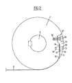
- the pulley 7, for example, keyed to the shaft 3, has at its periphery a recess of the shape shown, having in particular a flat part 9 inside the cylindrical contour of the pulley and which is connected by a rounded 10 to a large radius with this cylindrical periphery to avoid any angulation of the belt 5.
- This belt 5 is constituted by a thin metal sheet, tinsel or high-tensile steel strip of very small thickness, and its first end 11, in contact with the pulley 7, preferably comprises a reinforcement constituted by two plates 12 which are each welded on one of the faces of this end 11.
- This reinforcement is applied to the rectilinear part 9 and is there fixed and positioned with precision thanks to a centering foot 13 which passes through an orifice made in the assembly of the end 11 and its reinforcements 12, as well as in a hole 14 made in the pulley.
- a filling part 15 whose inner contour exactly matches the contour of the recess and the reinforcement, and whose outer contour very exactly reconstructs the cylindrical surface of the pulley 7 which had been removed by this recess, and this up to the rounding 10.
- This filling part 15 also includes an orifice 16 for the passage of the centering foot 13, as well as another stepped orifice 17 allowing the passage of a fixing screw 18 which is screwed into a tapped hole 19 of the pulley. In this way, during the rotation of the pulley 7, after the belt 5 has wound a full turn, covering the filling part 15, it is wound again on itself over an increased radius of a tiny amount, thanks to the thinness of the belt used.
- the other pulley 8 has a similar attachment for the belt 6, but oriented in the opposite direction and with a suitable angular setting.
- the second end 20 of the belt 5, or 21 of the belt 6, likewise comprises an end reinforcement similar to 12 to allow the fixing of these two ends on the mobile M.
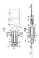
- the other end 20 is preferably fixed to the mobile M by means of an elastic compensation device C , shown in detail in FIG. 3.
- This essentially comprises a compression spring constituted by a stack of elastic washers 23 contained in a cylindrical housing 24 and traversed by a traction and guide rod 25.
- This rod 25 passes through the bottom 26 of the housing 24, and its outer end comprises a yoke 27 in which the end 20 is fixed by means of a through fastening 28.
- the other end of the rod 25 is threaded and comprises a nut 29 which presses, via a washer d 'support 30, on the elastic stack 23.
- the housing 24 can be closed by a plug 31, and the entire housing 24, externally threaded using a fine thread, passes through an end wall 32 of the mobile M, while a notched nut 33 is screwed onto the threaded part by pressing on 32 and allows the compression of the elastic stack 23 to be adjusted.
- This device thus makes it possible to precisely adjust the preload of all of the belts 5 and 6, given that an excess of tension would risk breaking these belts, while an insufficient tension would not allow the mobile M d '' exert the desired effort without introducing undesirable games.
- This elastic compensation device C 1 is therefore useful in all cases, and in particular in the envisaged case where the winding of the belts takes place over more than one turn, in order also to compensate for the minute variations in the winding radius such as set out above.
- the embodiment which has just been described for the translational movement of the mobile M relative to the plate P is applicable, whatever the orientation of the movement, to all cases where the dimension of the mobile in the direction of movement is much greater than the corresponding dimension of the support, which in this case is P.
- the double pulley 7-8 is arranged between the ends 20 and 21, the rectilinear parts of the belts 5 and 6 are in the same plane, tangent to the assembly of the two pulleys, and, from the fixing points 21 and 22, the belts therefore converge towards this double pulley.
- the sliding guide means can be constituted by a slide 101 cooperating with four grooved rollers 102 but, taking into account the fact that, in this case, the mobile P is short and the support B larger in the vertical direction, it is preferably the slide 101 which is now fixed and the rollers 102 mobile with the plate P, whereas, in the first example, it is the slide 1 which was mobile and the rollers 2 in a fixed position in the horizontal direction.
- the references 103 to 108 designate parts identical to parts 3 and 8 of the previous example, except for the length of the belts which is suitable for the desired stroke.
- the major difference comes from the fact that the two fixing points 122a and 122b of the belts 105 and 106 are relatively close together, since they are adapted to the vertical dimension of the plate P, and that, if they are always offset axially in the direction of the 'axis of the shaft 103, from these two fixing points, the two belts 105 and 106 start diverging, one towards the pulley 107, and the other towards an additional return pulley 150 whirling madly around a shaft 151 parallel to the shaft 103.
- the two strands 105 and 106 of belts are therefore always in the same plane, which this time is tangent both to the double pulley 107 and 108 and to the return pulley 150. From the latter, the belt 106 starts again towards the element 108 of the double pulley 107-108.
- the housing 124 containing the elastic washers 123 instead of pressing on the fixed part 32, is itself fixed to the reinforced end 122 of the belt 106 by means of the plug 131 which is in form of clevis to allow a through fixing or axis of attachment.
- the clevis 127 is fixed in an adjustable manner at the end of the rod 125, for example by means of a threaded connection and a lock nut. , as shown.
- the previous nut 29 is replaced by a head 129 which rests, still by means of a support washer 130, on the elastic stack 123.
- two 134 dishes made on the projecting part of this rod make it possible to ensure its rotational drive during adjustment.
- This second mode of application concerning the case where the mobile is shorter than the support, can also be used in all directions and, in the particular case just described, where it is used to move vertically the whole of the plate P and of the horizontal arm mechanism M, it is naturally possible, in the usual way, to compensate for the weight of this mobile assembly by means of a counterweight not shown.
- Such an arm with double displacement in horizontal and vertical translation is particularly suitable for making robot arms with Cartesian displacement, in which case it is particularly advantageous to have large strokes and large gears with space-saving servomotors and pulleys.
- the invention also applies in all cases where it is desired to transform a rotational movement of a shaft into a rectilinear translational movement.
Landscapes
- Engineering & Computer Science (AREA)
- General Engineering & Computer Science (AREA)
- Mechanical Engineering (AREA)
- Robotics (AREA)
- Transmission Devices (AREA)
- Manipulator (AREA)
- Devices For Conveying Motion By Means Of Endless Flexible Members (AREA)
Claims (7)
Applications Claiming Priority (2)
| Application Number | Priority Date | Filing Date | Title |
|---|---|---|---|
| FR8117427 | 1981-09-15 | ||
| FR8117427A FR2512909B1 (fr) | 1981-09-15 | 1981-09-15 | Mecanisme de translation rectiligne a poulies et courroies |
Publications (2)
| Publication Number | Publication Date |
|---|---|
| EP0074883A1 EP0074883A1 (de) | 1983-03-23 |
| EP0074883B1 true EP0074883B1 (de) | 1984-12-27 |
Family
ID=9262162
Family Applications (1)
| Application Number | Title | Priority Date | Filing Date |
|---|---|---|---|
| EP82401619A Expired EP0074883B1 (de) | 1981-09-15 | 1982-09-02 | Vorrichtung zur Übertragung geradliniger Bewegungen mittels Riemenscheiben und Treibriemen |
Country Status (5)
| Country | Link |
|---|---|
| US (1) | US4537084A (de) |
| EP (1) | EP0074883B1 (de) |
| JP (1) | JPS5857556A (de) |
| DE (1) | DE3261701D1 (de) |
| FR (1) | FR2512909B1 (de) |
Families Citing this family (27)
| Publication number | Priority date | Publication date | Assignee | Title |
|---|---|---|---|---|
| EP0330291B1 (de) * | 1985-03-23 | 1991-08-28 | Toto Ltd. | Verfahren zum Regeln der Position eines verschiebbaren Körpers |
| US4628548A (en) * | 1985-03-23 | 1986-12-16 | Toto Ltd. | Device and method of moving and controlling the position of a slidable body such as used for body cleansing |
| JPS6226675A (ja) * | 1985-07-29 | 1987-02-04 | Toshiba Corp | デイスク記憶装置 |
| US4724715A (en) * | 1986-04-30 | 1988-02-16 | Culver Craig F | Control mechanism for computer keyboard and the like |
| DE3628329C2 (de) * | 1986-08-21 | 1995-05-18 | Mueller Arnold Gmbh Co Kg | Einrichtung zur Erzeugung von Linearbewegungen |
| US4813292A (en) * | 1986-12-01 | 1989-03-21 | Maxaxam Corporation | Mechanical drive with multi-ply tape |
| US4882881A (en) * | 1987-02-24 | 1989-11-28 | Progressive Blasting Systems, Inc. | Robot positioner and seal arrangement for a closed chamber |
| GB2210350A (en) * | 1987-09-25 | 1989-06-07 | Kemble Instr Company Limited | Machine drive system |
| US5064340A (en) * | 1989-01-20 | 1991-11-12 | Genmark Automation | Precision arm mechanism |
| US5063334A (en) * | 1989-07-24 | 1991-11-05 | Canon Kabushiki Kaisha | Orthogonal two-axis moving apparatus |
| US5076517A (en) * | 1989-08-14 | 1991-12-31 | United Technologies Corporation | Programmable, linear collective control system for a helicopter |
| SE463219B (sv) * | 1989-10-16 | 1990-10-22 | Sky Park Ab | Linjaer vaexel saerskilt vid transfervagn i parkeringshus |
| US5198736A (en) * | 1990-11-15 | 1993-03-30 | Canon Kabushiki Kaisha | Orthogonal two-axis moving apparatus |
| FR2670840B1 (fr) * | 1990-12-20 | 1993-03-19 | Diebolt Remy | Actionneur d'articulation pour la mise en óoeuvre de tous mouvements rectilignes ou rotatifs. |
| JP3293638B2 (ja) * | 1991-03-15 | 2002-06-17 | 日本トムソン株式会社 | Xy駆動装置 |
| US5599268A (en) * | 1994-07-20 | 1997-02-04 | Tetra Laval Holdings & Finance S.A. | Belt driven linear transport apparatus for packaging machine |
| DE19604204A1 (de) * | 1996-02-06 | 1997-08-07 | Kodak Ag | Transportvorrichtung zum linearen Bewegen eines Transporttisches |
| US7594912B2 (en) | 2004-09-30 | 2009-09-29 | Intuitive Surgical, Inc. | Offset remote center manipulator for robotic surgery |
| DE10346450B4 (de) | 2002-10-08 | 2020-06-25 | Smc K.K. | Elektrisches Stellglied |
| FR2852373B1 (fr) * | 2003-03-14 | 2005-04-15 | Commissariat Energie Atomique | Transmission a vis, ecrou et cable |
| US9261172B2 (en) | 2004-09-30 | 2016-02-16 | Intuitive Surgical Operations, Inc. | Multi-ply strap drive trains for surgical robotic arms |
| US10646292B2 (en) | 2004-09-30 | 2020-05-12 | Intuitive Surgical Operations, Inc. | Electro-mechanical strap stack in robotic arms |
| US8128074B2 (en) * | 2006-11-14 | 2012-03-06 | General Electric Company | Automatic tensioning mount for belts |
| DK2375104T3 (da) * | 2008-12-19 | 2013-05-13 | Kawabuchi Mechanical Engineering Lab Inc | Mekanisme, som bevæger sig lineært og kan forlænges, og robotarm, der er udstyret med en mekanisme, der bevæger sig lineært og kan forlænges |
| CN104948687B (zh) * | 2015-05-07 | 2019-03-19 | 东方晶源微电子科技(北京)有限公司 | 一种适用于光机检测系统的带传动机构 |
| DE102019113372B4 (de) * | 2019-05-20 | 2022-03-31 | Gerhard Schubert Gmbh | Roboterarm sowie Verfahren zu seiner Steuerung |
| CN115673841B (zh) * | 2022-10-31 | 2024-01-26 | 无锡中叶合金制品有限公司 | 一种带轮加工用自动上下料装置 |
Family Cites Families (25)
| Publication number | Priority date | Publication date | Assignee | Title |
|---|---|---|---|---|
| DE35543C (de) * | O. GAUHE in Oberlahnstein | Seilschlösser mit selbstthätig einziehenden Keilen und umgelegten Seilenden | ||
| US55344A (en) * | 1866-06-05 | 1866-06-05 | Improved curtain-fixture | |
| US1006950A (en) * | 1911-06-06 | 1911-10-24 | Clifford L Keddy | Elastic turnbuckle. |
| CH99570A (fr) * | 1921-08-12 | 1923-06-16 | Inc C E Johansson | Dispositif pour convertir un léger mouvement rectiligue en un mouvement circulaire amplifié. |
| US1921402A (en) * | 1931-06-25 | 1933-08-08 | Dayton Scale Co | Tape drive |
| US1932305A (en) * | 1932-06-10 | 1933-10-24 | Jeumont Forges Const Elec | Surfacing apparatus |
| US2588642A (en) * | 1946-07-31 | 1952-03-11 | Wagner Electric Corp | Antibacklash coupling |
| CH299015A (fr) * | 1951-05-11 | 1954-05-31 | Gear Grinding Company Limited | Mécanisme comprenant un coulisseau relié à un organe rotatif par au moins deux bandes. |
| US2677923A (en) * | 1952-03-15 | 1954-05-11 | Parker John William | Table-actuating means for surface grinders |
| US2820187A (en) * | 1952-05-05 | 1958-01-14 | Parsons Corp | Motor controlled apparatus for positioning machine tool |
| US2837707A (en) * | 1954-01-21 | 1958-06-03 | British Thomson Houston Co Ltd | Servosystem controlled contour machining apparatus |
| FR1198914A (fr) * | 1957-08-05 | 1959-12-10 | Arnold & Stolzenberg G M B H | Mécanisme à renversement de course |
| DE1102515B (de) * | 1958-10-18 | 1961-03-16 | Kochs Adler Ag | Zugmitteltrieb zur Erzeugung von Hubbewegungen, insbesondere bei Naehmaschinen |
| US3003357A (en) * | 1960-01-25 | 1961-10-10 | American Machine & Metals | Motion transmitting device |
| FR1274566A (fr) * | 1960-09-12 | 1961-10-27 | Soc Optique Mec Haute Prec | Dispositif de transformation de précision d'un mouvement de rotation en un mouvement de translation |
| FR1359372A (fr) * | 1963-03-22 | 1966-06-17 | Ringard télescopique | |
| DE1184478B (de) * | 1963-12-27 | 1964-12-31 | Hilgers A G | Windentrommel mit einer Ausnehmung im Trommelmantel zum loesbaren Befestigen des aufliegenden Seil- oder Kettenendes |
| US3267812A (en) * | 1964-07-22 | 1966-08-23 | Gleason Works | Flexible band drive |
| US3429195A (en) * | 1967-08-15 | 1969-02-25 | Lear Siegler Inc | Lead mechanism |
| US3645144A (en) * | 1970-06-22 | 1972-02-29 | Carrier Corp | Cable tensioning structure for centrifugal compressor control |
| CH589518A5 (de) * | 1975-12-08 | 1977-07-15 | Hermes Precisa International | |
| US4059021A (en) * | 1976-06-25 | 1977-11-22 | Abram N. Spanel | Apparatus for converting oscillatory motion to reciprocating motion |
| US4161004A (en) * | 1977-04-05 | 1979-07-10 | Shugart Associates | Head positioning mechanism for recording/playback machine |
| US4170146A (en) * | 1977-08-18 | 1979-10-09 | Micro Peripherals, Inc. | Mechanism for transforming rotary motion to linear motion adapted for driving a magnetic head |
| DE2807856A1 (de) * | 1978-02-23 | 1979-09-06 | Mfe Corp | Positioniervorrichtung |
-
1981
- 1981-09-15 FR FR8117427A patent/FR2512909B1/fr not_active Expired
-
1982
- 1982-09-02 DE DE8282401619T patent/DE3261701D1/de not_active Expired
- 1982-09-02 EP EP82401619A patent/EP0074883B1/de not_active Expired
- 1982-09-09 JP JP57156016A patent/JPS5857556A/ja active Pending
- 1982-09-10 US US06/416,714 patent/US4537084A/en not_active Expired - Fee Related
Also Published As
| Publication number | Publication date |
|---|---|
| FR2512909B1 (fr) | 1987-02-20 |
| EP0074883A1 (de) | 1983-03-23 |
| JPS5857556A (ja) | 1983-04-05 |
| US4537084A (en) | 1985-08-27 |
| FR2512909A1 (fr) | 1983-03-18 |
| DE3261701D1 (en) | 1985-02-07 |
Similar Documents
| Publication | Publication Date | Title |
|---|---|---|
| EP0074883A1 (de) | Vorrichtung zur Übertragung geradliniger Bewegungen mittels Riemenscheiben und Treibriemen | |
| EP0664859B1 (de) | Bremsmotor mit geringen abmessungen | |
| FR2748054A1 (fr) | Dispositif de verrouillage motorise pour vehicule automobile comportant des moyens perfectionnes de limitation de la course du pene | |
| EP0014120B1 (de) | Pipette mit positiver Verstellung | |
| EP1370388B1 (de) | Vorrichtung zum antreiben und damit hergestelltes spannwerkeug | |
| FR2644542A1 (fr) | Dispositif tendeur a reglage par ressort | |
| FR2753920A1 (fr) | Tete d'outil pour le finissage par enlevement de copeaux d'une surface d'une piece a usiner | |
| EP0032098B1 (de) | Vorrichtung zum Entnehmen und Wiederabgeben wählbarer Flüssigkeitsmengen mit einer numerischen Anzeige | |
| WO2005077585A1 (fr) | Outil de serrage, en particulier pince a souder, avec un systeme de compensation | |
| FR2617548A1 (fr) | Regulateur automatique de la longueur de cables de commande | |
| FR2509466A1 (fr) | Capteur de deplacement inductif pour organe de reglage fluidique | |
| EP1221000B1 (de) | Spannvorrichtung in riemen-, ketten oder seilgetrieben zur übertragung der rotationsbewegung | |
| EP0091010B1 (de) | Kraftmessvorrichtung | |
| EP0564345B1 (de) | Hochleistungs-Bördelmaschine zum Verschliessen von Konservendosen | |
| EP0549390B1 (de) | Kugelhahn mit zurücknehmbarer Dichtung | |
| EP0234171B1 (de) | Ausdrehkopf | |
| FR3050494A1 (fr) | Vis a faibles pertes de matiere pour systeme de freinage de vehicule | |
| FR2629887A1 (fr) | Frein a disque a etrier coulissant a commande mecanique | |
| FR2705079A1 (fr) | Dispositif de commande pour frein et dérailleur de cycle. | |
| BE465209A (de) | ||
| FR2459891A1 (fr) | Dispositif d'actionnement a pression de fluide | |
| FR2779369A1 (fr) | Dispositif de serrage du type "pilote" ou analogue | |
| EP0761358A1 (de) | Gewindebohrwerkzeug verwendet in einer Presse | |
| EP0326501A1 (de) | Vorrichtung und Verfahren zum Positionieren eines Werkzeughalters entlang einer Achse | |
| FR2915949A1 (fr) | Ensemble de direction d'un vehicule automobile. |
Legal Events
| Date | Code | Title | Description |
|---|---|---|---|
| PUAI | Public reference made under article 153(3) epc to a published international application that has entered the european phase |
Free format text: ORIGINAL CODE: 0009012 |
|
| 17P | Request for examination filed |
Effective date: 19820906 |
|
| AK | Designated contracting states |
Designated state(s): DE GB IT SE |
|
| ITF | It: translation for a ep patent filed | ||
| GRAA | (expected) grant |
Free format text: ORIGINAL CODE: 0009210 |
|
| AK | Designated contracting states |
Designated state(s): DE GB IT SE |
|
| REF | Corresponds to: |
Ref document number: 3261701 Country of ref document: DE Date of ref document: 19850207 |
|
| PLBE | No opposition filed within time limit |
Free format text: ORIGINAL CODE: 0009261 |
|
| STAA | Information on the status of an ep patent application or granted ep patent |
Free format text: STATUS: NO OPPOSITION FILED WITHIN TIME LIMIT |
|
| 26N | No opposition filed | ||
| PGFP | Annual fee paid to national office [announced via postgrant information from national office to epo] |
Ref country code: DE Payment date: 19890530 Year of fee payment: 8 |
|
| PGFP | Annual fee paid to national office [announced via postgrant information from national office to epo] |
Ref country code: SE Payment date: 19890821 Year of fee payment: 8 |
|
| PGFP | Annual fee paid to national office [announced via postgrant information from national office to epo] |
Ref country code: GB Payment date: 19890831 Year of fee payment: 8 |
|
| ITTA | It: last paid annual fee | ||
| PG25 | Lapsed in a contracting state [announced via postgrant information from national office to epo] |
Ref country code: GB Effective date: 19900902 |
|
| PG25 | Lapsed in a contracting state [announced via postgrant information from national office to epo] |
Ref country code: SE Effective date: 19900903 |
|
| GBPC | Gb: european patent ceased through non-payment of renewal fee | ||
| PG25 | Lapsed in a contracting state [announced via postgrant information from national office to epo] |
Ref country code: DE Effective date: 19910601 |
|
| EUG | Se: european patent has lapsed |
Ref document number: 82401619.0 Effective date: 19910527 |