EP0074927A2 - Montage de commutation avec une fibre optique - Google Patents
Montage de commutation avec une fibre optique Download PDFInfo
- Publication number
- EP0074927A2 EP0074927A2 EP82810374A EP82810374A EP0074927A2 EP 0074927 A2 EP0074927 A2 EP 0074927A2 EP 82810374 A EP82810374 A EP 82810374A EP 82810374 A EP82810374 A EP 82810374A EP 0074927 A2 EP0074927 A2 EP 0074927A2
- Authority
- EP
- European Patent Office
- Prior art keywords
- optical fiber
- light
- switching device
- light sensor
- cable
- Prior art date
- Legal status (The legal status is an assumption and is not a legal conclusion. Google has not performed a legal analysis and makes no representation as to the accuracy of the status listed.)
- Granted
Links
Images



Classifications
-
- G—PHYSICS
- G02—OPTICS
- G02B—OPTICAL ELEMENTS, SYSTEMS OR APPARATUS
- G02B6/00—Light guides; Structural details of arrangements comprising light guides and other optical elements, e.g. couplings
- G02B6/24—Coupling light guides
- G02B6/26—Optical coupling means
- G02B6/35—Optical coupling means having switching means
-
- G—PHYSICS
- G02—OPTICS
- G02B—OPTICAL ELEMENTS, SYSTEMS OR APPARATUS
- G02B6/00—Light guides; Structural details of arrangements comprising light guides and other optical elements, e.g. couplings
- G02B6/24—Coupling light guides
- G02B6/26—Optical coupling means
- G02B6/35—Optical coupling means having switching means
- G02B6/3592—Means for removing polarization dependence of the switching means, i.e. polarization insensitive switching
-
- H—ELECTRICITY
- H03—ELECTRONIC CIRCUITRY
- H03K—PULSE TECHNIQUE
- H03K17/00—Electronic switching or gating, i.e. not by contact-making and –breaking
- H03K17/94—Electronic switching or gating, i.e. not by contact-making and –breaking characterised by the way in which the control signals are generated
- H03K17/941—Electronic switching or gating, i.e. not by contact-making and –breaking characterised by the way in which the control signals are generated using an optical detector
-
- G—PHYSICS
- G02—OPTICS
- G02B—OPTICAL ELEMENTS, SYSTEMS OR APPARATUS
- G02B6/00—Light guides; Structural details of arrangements comprising light guides and other optical elements, e.g. couplings
- G02B6/24—Coupling light guides
- G02B6/26—Optical coupling means
- G02B6/35—Optical coupling means having switching means
- G02B6/3564—Mechanical details of the actuation mechanism associated with the moving element or mounting mechanism details
- G02B6/3568—Mechanical details of the actuation mechanism associated with the moving element or mounting mechanism details characterised by the actuating force
- G02B6/3574—Mechanical force, e.g. pressure variations
-
- G—PHYSICS
- G02—OPTICS
- G02B—OPTICAL ELEMENTS, SYSTEMS OR APPARATUS
- G02B6/00—Light guides; Structural details of arrangements comprising light guides and other optical elements, e.g. couplings
- G02B6/24—Coupling light guides
- G02B6/26—Optical coupling means
- G02B6/35—Optical coupling means having switching means
- G02B6/3594—Characterised by additional functional means, e.g. means for variably attenuating or branching or means for switching differently polarized beams
Definitions
- the invention relates to a switching device with an optical fiber according to the preamble of claim 1.
- the optical fiber has an arcuate section at the location of the button, which is freed from the jacket of the optical fiber in the region of its apex and on its outside.
- a small deflectable plate is arranged at a short distance above this apex region, the refractive index of which is greater than that of the core of the optical fiber.
- the known switching device has various disadvantages.
- the control line formed by the optical fiber has a considerable length and if one or more actuators for influencing the intensity of the light transmitted through the optical fiber are to be arranged at any points along the optical fiber which are not fixed prior to the laying of the optical fiber, that is known switching device little suitable. Since the switching or detection criterion is a pure intensity criterion, other intensity losses can adversely affect the sensitivity of the light detector to discrimination.
- the section of the optical fiber to be influenced has to be bent in the shape of a hairpin or horseshoe, which makes it difficult or even impossible to actuate elements at any point on an elongated optical fiber without using costly and optically problematic connecting elements, e.g. Plug connections to arrange.
- alarm and measuring devices are known in which coherent light from a laser is fed into a deformable multimode optical fiber that serves as a detector line, and consequently at the optical fiber end by the light detector patterns of light spots occurring from transmission time differences are monitored.
- This light spot pattern changes when the optical fiber is shifted (e.g. in an intrusion detection system) or exposed to acoustic vibrations (e.g. in an underwater sound detection system). The change in position of the light spot pattern is determined by the light detector in order to trigger an alarm or to generate a measured variable.
- a disadvantage of the known alarm and measuring devices is that temperature changes and vibrations and vibrations other than those to be detected generate interference signals which make it difficult or even impossible to determine a targeted effect on the optical fiber.
- the claimed subject matter of the invention provides a switching device of the type mentioned at the outset, which detects a targeted, repeatable pressure or displacement action on the optical fiber at any point along the optical fiber with elimination of interference and the triggering of an ent speaking switching operation allows.
- actuating devices of the type claimed can be arranged or formed in a simple manner at any point or continuously along an optical fiber, the optical fiber being essentially of any length and any length.
- the switching device according to the invention is thus particularly suitable for a universal, cost-effective production of current-free, explosion-proof and corrosion-proof switchgear in buildings instead of the usual electrical wiring and switches, the course or placement of which must be known to be determined in advance or only subsequently changed with considerable effort or can be added.
- the optical fiber can in principle be a single-mode or a multimode optical fiber.
- a single-mode optical fiber it is expedient to use the light detector arranged at the end of the optical fiber to measure the birefringence of the optical fiber, i.e. the phase shift of two light waves with different polarization directions, in particular orthogonal polarization directions, and to change these polarizations or the corresponding light intensities on at least one optical fiber section to apply transverse pressure.
- the light detector arranged at the end of the optical fiber to detect the position of the light spots (speckling) occurring at the end of the optical fiber due to local phase shifts of the light waves and to shift at least one optical fiber section laterally to change the distribution of these light spots.
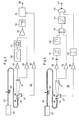
- a monomode optical fiber 1 is arranged as a control line, for example for triggering electrical switching processes in a building, the length of which can be considerable and which, while avoiding very small radii of curvature, can be laid curved.
- the core diameter is known to be only a few wavelengths long, so that only the basic mode is capable of propagation.
- the optical fiber or its jacket is surrounded by a protective covering.
- a laser light source 3 is arranged at one end 2 of the optical fiber 1.
- the laser light is guided through a lens arrangement 4 onto the end face of the optical fiber 1 at the end 2.
- a polarization element 5 e.g. an ⁇ . / 4 plate, arranged to generate a circular polarization of the light fed into the optical fiber 1.
- a light detector At the other end 6 of the optical fiber 1 there is a light detector, generally designated 7. Furthermore, at any point 8 along the optical fiber 1 there is an actuator 9, indicated by arrows, by means of which a transversal pressure can be exerted on the bare optical fiber 1, that is to say from its protective covering and possibly also from its jacket.
- the actuating element 9 and the light detector 7 are designed such that when the actuating element 9 is actuated, preferably by pressing a finger on the hand, the Light detector 7 detects a change in the phase relationships of the light waves transmitted by optical fiber 1 and outputs a corresponding switching or control signal at its output 10.
- the switching device shown is based on the effect that the transverse pressure exerted by the actuator 9 on the optical fiber 1 at the point 8 changes the refractive index in an anisotropic manner.
- the light detector 7 is designed such that it has the birefringence of the optical fiber 1, i.e. measures the phase shift between two light waves with preferably orthogonal polarizations.
- the difference in the light intensities according to two orthogonal polarizations or their change when the actuator 9 is actuated can be measured in a simple manner at the end 6 of the optical fiber 1.
- a polarizer 11 of a known type is arranged in the light bundle emerging from the end 6 of the optical fiber 1, which polarizer 11 normally converts the at least approximately circularly polarized light into two light bundles 12 and 13 with different directions of propagation and different, preferably orthogonal polarization direction splits.
- Each of these light beams 12, 13 falls on a photoelectric sensor 14 or 15, which are connected to an evaluation circuit.
- This electronic evaluation circuit which is only indicated schematically here, comprises a circuit part 16 with a separate bandpass filter and rectifier for each of the two output signals of the sensors 14 and 15, and a difference-forming circuit, for example a differential amplifier, for the two rectified signals.
- the difference signal arrives at a trigger circuit 17 which emits the switching or control signal mentioned at its output 10 when the light intensities change relative to each other by a certain minimum amount according to the actuation of the actuating element 9 in accordance with the two orthogonal polarization directions.
- the response threshold of the trigger circuit 17 can be determined taking into account the requirements for a safe function of the light detector 7, be it by specifying a predetermined value or as a function of the average intensity of the light emerging from the optical fiber. In the latter case, the output signals of the sensors 14 and 15 can be fed to a summing circuit 18, the output signal of which controls the response threshold of the trigger circuit 17. Further details of the electronic circuit parts mentioned are explained in more detail below with reference to FIG. 3.
- the use of a laser as the light source 3 would not in itself be necessary since the light source can only have a weak temporal coherence. However, since a single transverse mode of oscillation is to be fed into the optical fiber, practically only one laser remains as the light source, which, however, can be a semiconductor laser in view of the low coherence requirements.
- the insertion of the circular polarization element 5 is expedient because local states of low sensitivity can thereby be avoided.
- a plurality of actuators 9 can also be arranged along the optical fiber 1.
- the optical fiber at least freed from its protective sheath at the point in question must be arranged on a base which ensures sufficient transmission of the force exerted by placing one or more fingers on the actuator to the optical fiber.
- 2a and 2b two exemplary embodiments of suitable actuators are shown schematically.
- the base consists of a piece of metal strip 19, for example a steel strip, on which the bare optical fiber section 8 lies, of course without the optical fiber being separated.
- a plurality of cylindrical pins 20 are arranged parallel to one another and transversely to the longitudinal direction of the optical fiber, the pins 20 being elastically mounted on the metal strip 19 in a manner not shown.
- a second chain of pins 21 is provided, the pins 20 and 21 facing each other in pairs and the optical fiber section 8 between the two chains of pins 20 and 21, which is not shown in FIG shown are elastically connected to each other or are elastically mounted.
- phase changes can be recorded using interferometric measurement methods will; this, however, requires a "reference", ie a second optical fiber, which means considerable effort and, when using semiconductor lasers with relatively low coherence, requires precise monitoring of the effective lengths of the optical fibers.
- the device described which is based on the detection of the light intensities in two different polarization directions, avoids the disadvantages mentioned.
- a relative phase change based on the force exerted, of the two parallel and perpendicularly polarized light waves of 1.0 rad / N be achieved.
- this phase change was about 0.7 rad / N.
- the phase changes achieved were about half as large. Birefringence could no longer be determined for optical fibers provided with a protective sheath.
- a multimode optical fiber is used in the device of FIG. 1 instead of the single-mode optical fiber 1, it is found that no global birefringence effect can be determined at the end of the optical fiber on the light detector side, since the light bundle, taken as a whole, is unpolarized.
- a multimode optical fiber it is known that there is either a core of approximately 50 to 600 ⁇ m in diameter with a cladding with a somewhat lower refractive index and a thickness of a few ⁇ m (stepped profile fiber) or a core of approximately 50 to 100 ⁇ m in diameter, which is continuously encased in a cladding with a lower refractive index and an outer diameter of about 200 pm.
- the coat is also surrounded by a protective covering.
- the light is not uniform over the cross section of the detector-side optical fiber end with sufficiently coherent, fed-in light, but is inhomogeneous and randomly distributed due to the local phase shifts of the light waves in the form of light spots (speckles, speckling).
- a birefringence caused by the pressure exerted on the optical fiber can be measured in accordance with the exemplary embodiment described with reference to FIG. 1.
- such a measurement method has considerable disadvantages because of the small dimensions of the light spots and their variable distribution over the cross section of the optical fiber due to external influences on the optical fiber.
- the coherent light of a laser 23 is fed into a multimode optical fiber 22 of any length, which can also be laid in a curved manner, with the aid of optical means, not shown, in order to have a light distribution in the form of at the open end 24 of the optical fiber 22 To achieve light spots (speckling).
- the optical fiber 22 provided with a protective covering is provided at one or more points with an elastic base 25, which causes a lateral deformation of the optical fiber when a slight pressure, indicated by an arrow, is exerted on the optical fiber 22, e.g. by means of light finger pressure, the lateral deformation can be less than 1 mm.
- a light detector, generally designated 26 is arranged at the end 24 of the optical fiber 22.
- the light detector 26 comprises one or more photoelectric light sensors 27, each of which detects a solid angle that is smaller than the dimension of an associated light spot. This dimension is determined by the core Knife of the optical fiber and determined by the wavelength of the light used. For a standard optical fiber with a core diameter of 50 ⁇ m and for red light or light in the near infrared range, the light spot dimension corresponds to an opening angle of approximately 30 mrad or 2 °.
- the use of light sensors that are too large reduces the modulation of the recorded signal.
- the number of light sensors to be arranged depends on the security required for triggering the light detector 26 with regard to the geometric deformation of the optical fiber caused by the mechanical action on the optical fiber; this number of sensors is therefore tied to the strength of the deformable base 25. In typical applications, one to four light sensors 27 are sufficient.
- a polarizer 28 can be arranged between the end 24 of the optical fiber 22 and the light sensors 27, which in principle increases the relative modulation of the received signals by a factor V2.
- the useful signal emitted by the light sensor (s) 27 is supplied by the changes in intensity of the light falling on the sensor 27, if, according to a local De formation of the optical fiber 22 changes the spotty light distribution at the end of the optical fiber 24.
- the electrical signal of each light sensor 27 is fed to a bandpass filter 30 via an amplifier 29 (for example an operational amplifier).
- the bandpass filter 30 can be made from the series connection of a low-pass filter and a high-pass filter with fixed or adjustable frequency-determining components (capacitors and resistors).
- the low-pass filter whose cut-off frequency is typically 10 Hz, weakens acoustic and mechanical disturbances (vibrations).
- the high-pass filter whose cut-off frequency is typically 1 to 4 Hz, suppresses disturbances of thermal origin.
- a rectifier circuit 31 connected to each bandpass filter 30 enables an increase in the sensitivity of the present light detector.
- the rectified signals of both light sensors 27 are then fed to a summing amplifier 32.
- the output of the summing amplifier 32 is connected to the input of a trigger circuit 34 via an RC integration element 33.
- the integration element 33 which has a time constant of approximately 0.1 s, has the effect that the trigger circuit 34 only responds when the change in position of the light spots detected by the light sensors 27 has reached an electrical signal of sufficient magnitude in terms of amplitude and duration.
- the triggering of the trigger circuit 34 for emitting a corresponding switching or control signal at its output 35 should only take place when the input signal reaches a certain response threshold, which is to be determined depending on the intended use of the switching device.
- This response threshold can be determined, for example, as a function of the mean of the sum of the intensities determined by the light sensors 27.
- a semitransparent mirror 36 is arranged in the beam path of the light emerging from the optical fiber end 24 as a beam splitter. The deflected light is from one another light sensor 37 totally detected.
- the measurement signal of the light sensor 37 is fed to the trigger circuit 34 via an amplifier 38 in order to determine its response threshold, in such a way that the trigger circuit 34 responds when the intensity corresponding to its input signal is greater than a small fraction of the total intensity.
- the fraction, electrically adjustable, for example in the amplifier 38, is selected taking into account the respective safety requirements and the intensity and modulation levels.
- the response threshold of the trigger circuit 34 can, however, also be permanently set by means of a direct voltage supplied via a potentiometer.
- FIG. 4 describes a switching device corresponding to the switching device of FIG. 3, but which contains a digitally operating light detector 39.
- the optical and electro-optical parts are the same as in FIG. 3 and are therefore also designated identically, namely the optical fiber 22, the laser 23, the base 25, the photoelectric light sensors 27, the polarizer 28, the further photoelectric light sensor 37, receives the light through the semi-transparent mirror 36, and also the amplifiers 29 and 38, which are connected to the output lines of the light sensor 27 and the light sensor 37, respectively.
- a threshold value detector 41 with hysteresis is connected to the output of each amplifier 29 in the light detector 39 via a capacitor 40 which roughly defines the lower response frequency, e.g. a Schmitt trigger, the output of which is connected to a digital bandpass filter 42.
- Separate inputs of an exclusive-OR gate or binary comparator 43 are connected to the outputs of all bandpass filters, the output of which is connected to the one input of a NAND gate 45 via an integration element 44.
- the other input of the NAND gate 45 is connected via a further threshold value detector 46 to the output of the amplifier 38 of the further light sensor 37.
- the NAND gate 45 has an output 47 for connecting a switching element for a consumer or the like.
- the light detector 39 of FIG. 4 operates in accordance with the light detector 26 of FIG. 3 already described, but it does a digital instead of an analog evaluation of the electrical signals emitted by the light sensors 27, 37.
- the advantage of the digital evaluation by the light detector 39 lies above all in a better, simpler and less expensive design option for the circuit parts 41 to 45 than integrated circuits and in the ideal filter compared to the analog evaluation Characteristic of the digital bandpass filter 42. Because of its digital design, this bandpass filter is particularly suitable for masking out mechanical and thermal disturbance variables which can arise in the optical fiber 22 and are converted by the light sensors 27 into corresponding electrical interference signals, which is the case, for example, when using the present optical fiber switching device in Vehicles can be of great importance.
- the signal at the output 47 of the NAND gate 45 otherwise corresponds to the signal at the output 35 of the light detector 26 in FIG. 3.
- the digital bandpass filter 42 can consist, for example, of the parallel connection of two retriggerable monoflops (ie monoflops which are retriggered by each input signal, even if the monoflop's own time has not yet expired), the outputs of the two monoflops each having an input of an AND Circuit are connected.
- the monoflops have their own times according to the period lengths of the input signal at the lower or the upper limit of the pass band of the bandpass filter, such that at the lower band limit that a monoflop is not yet running, that is, is not yet returning to the idle state, and at the upper band limit the other monoflop is continuously reset.
- the pass band of the digital bandpass filter 42 can extend, for example and advantageously from 0.5 Hz to 3 Hz, in order to eliminate thermal and mechanical and acoustic interference on the one hand.
- the exclusive-OR gate 43 determines each time and outputs a corresponding output pulse that, or if a change in the light intensity occurs at a photoelectric light sensor 27 by changing the position of the light spot in question at a certain point in time and within the limits determined by the threshold value detectors 41 and bandpass filters 42 , but not on the other light sensor 27.
- the integration element 44 has the same task as the integration element 33 of FIG. 3.
- FIG. 5 Another embodiment of a digitally operating light detector is shown schematically in FIG. 5.
- the optical and mechanical parts of the switching device which correspond to those of FIG. 4, have been omitted.
- an amplifier 29 is in turn connected to each of the two photoelectric light sensors 27, the output of which is connected via a capacitor 40 to the series connection of a threshold value detector 41 and a digital bandpass filter 42.
- the outputs of the bandpass filter 42 are also connected to inputs of an exclusive OR gate or binary comparator 43.
- the output of the exclusive OR gate or binary comparator 43, at which inequality pulses of the incorrect bit comparison appear, is connected to the counting input of a decimal or dual counter 48, which thus counts the offered pulses.
- the various counting stages of the counter 48 are individually connected to connections of a selector switch 49, on which a trigger element 50, e.g. a storage element is connected, which in turn is a switching process for a consumer 51, e.g. a light bulb, triggers.
- the selector switch 39 is used to set the digital sensitivity of the light detector described, i.e. for setting the number of pulses of the exclusive OR gate 43 (i.e. the false bit rate) until the triggering element 50 is triggered.
- the counter 48 thus corresponds to the integrating element 44 in FIG. 4, with the additional setting option.
- FIGS. 6a to 6d Exemplary embodiments for the elastic base 25 (FIGS. 3 and 4) are shown in FIGS. 6a to 6d.
- 6a a section of the optical fiber 22 is attached to a plastic foam piece 52, for example glued on.
- Plastic foam profile pieces can also be used, for example a semicircular hollow profile 53 according to FIG. 6b or a T profile 54 according to FIG. 6c or a plastic foam piece 55 surrounding the optical fiber 22 according to FIG. 6d. All of these documents can be placed under an existing, ie laid optical fiber without difficulty, without the optical fiber having to be processed or separated.
- a further embodiment of the elastic underlays for the optical fiber can consist in the fact that the optical fiber is surrounded over its entire length to be laid by a plastic jacket in which the optical fiber is embedded in such a way that it can be moved laterally by finger pressure at any point and in any direction small distance can be moved.
- FIG. 7a shows a section of such a light guide switch cable 56 in a longitudinal section
- FIGS. 7b and 7c show cross sections of this cable for a four-edge version or a round version. It can be seen from these figures that the optical fiber 22 is embedded in a plastic jacket 57 in such a way that 57 minutes between the outer surface of the optical fiber 22 and the adjacent plastic jacket at least there is a cavity 58 which extends helically along the optical fiber 22.
- the optical fiber 22 abuts against the plastic jacket 57 via at least one rib 59 which extends helically along the optical fiber 22.
- the plastic jacket 57 can be designed as a square profile (FIG. 7b) or as a round profile (FIG. 7c).
- Such a light guide switch cable or opto switch cable 56 can be laid as desired and, together with a laser light source and a light detector according to FIG. 3, 4 or 5, represents a switching device which can be operated by simple finger pressure or the like. Due to the plastic sheath 57 extending over the entire length of the optical fiber 22 and its all-round symmetry with respect to the optical fiber can be triggered at any point.
- a further advantageous embodiment of an optical switch cable consists in arranging the optical fiber 22 back and forth in an elastically flexible plastic sheath in order to obtain a round cable or preferably a flat cable 60 (flat ribbon).
- the width of such a flat cable 60 can be approximately 5 to 10 mm, its length can be up to 1 km, so that such a switch cable is particularly suitable for tight laying on the wall a long corridor or tunnel. The desired switching process can then be triggered by lightly pressing the cable at any point.
- switch cable 60 Of particular advantage with switch cable 60 is the fact that at the same cable end the coherent light is fed into one end of the optical fiber 22 by a laser 23 and the detection of the light emerging from the other end of the optical fiber 22 by a light detector 26, 39 according to FIG 3, 4 or 5 can take place.
- the parallel routing of the optical fiber 22 in the cable 60 also ensures a change in the light spot pattern at the end of the optical fiber even with very little finger pressure.
- a switching device with a meandering optical fiber cable 56 laid on a wall 61 in a plaster layer 62 according to Fig. 7 is shown schematically, with one end of the optical fiber of the cable 56 according to Fig. 3, 4 or 5 a laser light source 23 and a light detector 26 or 39 are connected to the other end.
- the triggering takes place by touching the cable 56 over the plaster layer 62 with the hand 63, which causes a slight lateral displacement of the optical fiber in the plastic jacket of the cable 56 is effected and the light detector 26 or 39 emits a corresponding switching signal.
- the light guide switch cable 56 can be laid over a large area in a flexible covering 64 of a floor 65 in a manner not shown. It is then triggered by entering this large-area floor switching device.
- a planar switching device for example for subsequent attachment to a wall, can be obtained by repeatedly embedding the optical fiber back and forth in an elastic, flat-band-shaped cable sheath (corresponding to FIG. 8) (corresponding to FIG. 9a).
- a flat cable 66 is shown in section in FIG. 10.
- the meandering back and forth optical fiber 22 is embedded in a band-shaped elastic plastic sheath 67, the width of which is approximately 100 to 200 mm and the thickness of 2 to 3 mm, the length of the plastic sheath 67 being arbitrary and the ends of the optical fiber 22 at the same end emerge from the plastic jacket 67.
- One surface of the plastic jacket 67 is provided with a self-adhesive adhesive layer 68 around the flat cable formed on a wall in a simple manner to be able to attach. So that a slight pressure can be exerted on the flat cable at any point in its width direction according to the arrows shown in order to trigger a switching operation without the individual strands of the optical fiber 22 having to be very close to one another, there is a thin one in the plastic sheath 67, the optical fiber 22 covering pressure plate 69, for example made of a plastic, embedded.
- FIG. 11 schematically shows a switching device, which in turn contains the optical fiber 22 and the laser 23 at one end of the optical fiber 22, an envelope of the optical fiber 22 not being shown. At one or more points of the optical fiber 22, it wraps around a transducer element 70, which is designed to be excited to corresponding radial vibrations by applied electrical alternating voltages.
- the transducer elements 70 are preferably piezoelectric planar oscillators, which excitation voltages via the multiplex method are used in each case a modulator / oscillator 71 or 72 are supplied.
- a frequency alternating voltage f 1 in the modulator / oscillator 71 modulates a high-frequency voltage whose frequency is in the range of 30 kHz by means of frequency modulation, and data information f 2 in the modulator / oscillator 72 by means of pulse code modulation, a further high-frequency voltage whose frequency is in the range of 40 kHz.
- the transducers 70 are excited to radial vibrations of corresponding frequencies, which act on the optical fiber 22 in the transverse direction.
- the light spot pattern at the other end of the optical fiber 22 changes not only as a function of, for example, manual pressure exerted on the optical fiber 22 at some point in accordance with the arrows shown, but also as a function of the aforementioned effects of the transducer 70.
- a light detector 73 assigned to the end of the optical fiber 22 not only contains, as shown, for example, in FIG. 3, a plurality of photoelectric light sensors 27, amplifiers 29, a sum amplifier 32 and an integration element 33, but also frequency or pulse demodulators.
- the bandpass filters corresponding to the bandpass filters 30 in Fig. 3 are ge in this embodiment called integrator downstream and comprise a first bandpass filter 74 with a pass band of, for example, 0.5 Hz to 3 Hz for filtering out the signal components which result from the manual pressure effects on the optical fiber 22 and are intended to actuate a switch S.
- Two further bandpass filters 75 and 76 connected to the light detector 73 filter out the information signals f 1 and f Z.
- An exemplary converter 70 is shown in more detail in FIG. 12.
- the loop can also be multiple in order to achieve a higher sensitivity.
Landscapes
- Physics & Mathematics (AREA)
- General Physics & Mathematics (AREA)
- Optics & Photonics (AREA)
- Mechanical Light Control Or Optical Switches (AREA)
- Mechanical Coupling Of Light Guides (AREA)
Priority Applications (1)
| Application Number | Priority Date | Filing Date | Title |
|---|---|---|---|
| AT82810374T ATE34055T1 (de) | 1981-09-11 | 1982-09-08 | Schalteinrichtung mit einer lichtleitfaser. |
Applications Claiming Priority (2)
| Application Number | Priority Date | Filing Date | Title |
|---|---|---|---|
| CH5914/81 | 1981-09-11 | ||
| CH591481 | 1981-09-11 |
Publications (3)
| Publication Number | Publication Date |
|---|---|
| EP0074927A2 true EP0074927A2 (fr) | 1983-03-23 |
| EP0074927A3 EP0074927A3 (en) | 1985-01-16 |
| EP0074927B1 EP0074927B1 (fr) | 1988-05-04 |
Family
ID=4301445
Family Applications (1)
| Application Number | Title | Priority Date | Filing Date |
|---|---|---|---|
| EP82810374A Expired EP0074927B1 (fr) | 1981-09-11 | 1982-09-08 | Montage de commutation avec une fibre optique |
Country Status (3)
| Country | Link |
|---|---|
| EP (1) | EP0074927B1 (fr) |
| AT (1) | ATE34055T1 (fr) |
| DE (1) | DE3278451D1 (fr) |
Cited By (2)
| Publication number | Priority date | Publication date | Assignee | Title |
|---|---|---|---|---|
| FR2613844A1 (fr) * | 1987-01-23 | 1988-10-14 | Jaeger | Dispositif concu pour interrompre ou attenuer un signal lumineux se propageant dans un guide optique |
| CN113067572A (zh) * | 2021-03-19 | 2021-07-02 | 东北大学 | 一种温控开关效应的联结型液芯反谐振光纤及其应用 |
Family Cites Families (6)
| Publication number | Priority date | Publication date | Assignee | Title |
|---|---|---|---|---|
| AT261266B (de) * | 1965-09-18 | 1968-04-10 | Schneider Co Optische Werke | Faseroptischer Analog-Digital-Umsetzer |
| NL7802054A (nl) * | 1977-02-23 | 1978-08-25 | Nedap Nv | Contactloos bedienbare kraan. |
| FR2418506A1 (fr) * | 1978-02-28 | 1979-09-21 | Comp Generale Electricite | Dispositif pour detecter la presence d'un objet le long d'une ligne |
| GB2019561B (en) * | 1978-04-20 | 1982-09-02 | Davies D E N | Telecommunication systems |
| US4297684A (en) * | 1979-03-26 | 1981-10-27 | Honeywell Inc. | Fiber optic intruder alarm system |
| US4268116A (en) * | 1979-10-26 | 1981-05-19 | Optelecom Incorporated | Method and apparatus for radiant energy modulation in optical fibers |
-
1982
- 1982-09-08 AT AT82810374T patent/ATE34055T1/de not_active IP Right Cessation
- 1982-09-08 EP EP82810374A patent/EP0074927B1/fr not_active Expired
- 1982-09-08 DE DE8282810374T patent/DE3278451D1/de not_active Expired
Cited By (3)
| Publication number | Priority date | Publication date | Assignee | Title |
|---|---|---|---|---|
| FR2613844A1 (fr) * | 1987-01-23 | 1988-10-14 | Jaeger | Dispositif concu pour interrompre ou attenuer un signal lumineux se propageant dans un guide optique |
| CN113067572A (zh) * | 2021-03-19 | 2021-07-02 | 东北大学 | 一种温控开关效应的联结型液芯反谐振光纤及其应用 |
| CN113067572B (zh) * | 2021-03-19 | 2024-04-16 | 东北大学 | 一种温控开关效应的联结型液芯反谐振光纤及其应用 |
Also Published As
| Publication number | Publication date |
|---|---|
| DE3278451D1 (en) | 1988-06-09 |
| EP0074927B1 (fr) | 1988-05-04 |
| EP0074927A3 (en) | 1985-01-16 |
| ATE34055T1 (de) | 1988-05-15 |
Similar Documents
| Publication | Publication Date | Title |
|---|---|---|
| DE3687438T2 (de) | Optische zeit-feld-reflektometrie. | |
| EP0696782B1 (fr) | Capteur optique de force compressive | |
| DE69032810T2 (de) | Fernmessung physikalischer Variablen mit faseroptischen Systemen | |
| DE69433154T2 (de) | Optische Reflexionsmessung im Zeitbereich | |
| DE19754910C2 (de) | Wellenlängendetektion an Faser-Bragg-Gitter-Sensoren | |
| DE69414011T2 (de) | Diagnostisches system fur fibergittersensoren | |
| DE3785394T2 (de) | Messanordnung und Methode mit mehreren Sensoren und einer Pulssignalquelle. | |
| DE60309291T2 (de) | (Faser-) Optischer Sensor mit geeigneter Modulation | |
| EP0199384B1 (fr) | Appareil de mesure optique | |
| DE69115773T2 (de) | System zur Lokalisierung von Fehlerstellen in einem elektrischen Leistungskabel mit Hilfe einer Anordnung zum Verlegen von optischen Fasern | |
| DE69828788T2 (de) | Integriertes optisches wellenleiterbauelement | |
| DE60014631T2 (de) | Dehnungsmessung | |
| EP0361588A1 (fr) | Capteur à fibre optique | |
| WO1979000180A1 (fr) | Indicateur de valeur limite et de valeur de mesure | |
| DE3137387A1 (de) | Faseroptisches messgeraet zum messen physikalischer und chemischer groessen | |
| DE2748173C3 (de) | Beschleunigungsmesser | |
| DE3145795A1 (de) | "faseroptisches messgeraet zum messen physikalischer groessen" | |
| EP1049916B1 (fr) | Detecteur de force a fibres optiques, utilisation dudit detecteur pour surveiller des aretes de fermeture, et procede pour la production dudit detecteur | |
| EP0074927A2 (fr) | Montage de commutation avec une fibre optique | |
| DE69729571T2 (de) | Ein optischer wellenlängenscanner versehen mit einem referenzsystem | |
| DE3833635C2 (fr) | ||
| DE3302089C2 (de) | Vorrichtung zur Messung der optischen Brechzahl von Flüssigkeiten | |
| DE3325945A1 (de) | Faseroptischer sensor und eine diesen enthaltende sensoreinrichtung | |
| DE69209412T2 (de) | Sensor | |
| DE3640519A1 (de) | Optischer lagemesswandler |
Legal Events
| Date | Code | Title | Description |
|---|---|---|---|
| PUAI | Public reference made under article 153(3) epc to a published international application that has entered the european phase |
Free format text: ORIGINAL CODE: 0009012 |
|
| AK | Designated contracting states |
Designated state(s): AT CH DE GB LI |
|
| PUAL | Search report despatched |
Free format text: ORIGINAL CODE: 0009013 |
|
| AK | Designated contracting states |
Designated state(s): AT CH DE GB LI |
|
| 17P | Request for examination filed |
Effective date: 19841204 |
|
| R17P | Request for examination filed (corrected) |
Effective date: 19841204 |
|
| GRAA | (expected) grant |
Free format text: ORIGINAL CODE: 0009210 |
|
| AK | Designated contracting states |
Kind code of ref document: B1 Designated state(s): AT CH DE GB LI |
|
| REF | Corresponds to: |
Ref document number: 34055 Country of ref document: AT Date of ref document: 19880515 Kind code of ref document: T |
|
| GBT | Gb: translation of ep patent filed (gb section 77(6)(a)/1977) | ||
| REF | Corresponds to: |
Ref document number: 3278451 Country of ref document: DE Date of ref document: 19880609 |
|
| PLBE | No opposition filed within time limit |
Free format text: ORIGINAL CODE: 0009261 |
|
| STAA | Information on the status of an ep patent application or granted ep patent |
Free format text: STATUS: NO OPPOSITION FILED WITHIN TIME LIMIT |
|
| 26N | No opposition filed | ||
| PGFP | Annual fee paid to national office [announced via postgrant information from national office to epo] |
Ref country code: AT Payment date: 19890804 Year of fee payment: 8 |
|
| PGFP | Annual fee paid to national office [announced via postgrant information from national office to epo] |
Ref country code: CH Payment date: 19890808 Year of fee payment: 8 |
|
| PGFP | Annual fee paid to national office [announced via postgrant information from national office to epo] |
Ref country code: GB Payment date: 19890831 Year of fee payment: 8 Ref country code: DE Payment date: 19890831 Year of fee payment: 8 |
|
| PG25 | Lapsed in a contracting state [announced via postgrant information from national office to epo] |
Ref country code: GB Effective date: 19900908 Ref country code: AT Effective date: 19900908 |
|
| PG25 | Lapsed in a contracting state [announced via postgrant information from national office to epo] |
Ref country code: LI Effective date: 19900930 Ref country code: CH Effective date: 19900930 |
|
| GBPC | Gb: european patent ceased through non-payment of renewal fee | ||
| REG | Reference to a national code |
Ref country code: CH Ref legal event code: PL |
|
| PG25 | Lapsed in a contracting state [announced via postgrant information from national office to epo] |
Ref country code: DE Effective date: 19910601 |