EP0074930A2 - Méthode générative pour l'usinage par enlèvement de copeaux de flancs de dents à denture en développante avec corrections du profil transversal et longitudinal - Google Patents
Méthode générative pour l'usinage par enlèvement de copeaux de flancs de dents à denture en développante avec corrections du profil transversal et longitudinal Download PDFInfo
- Publication number
- EP0074930A2 EP0074930A2 EP82810386A EP82810386A EP0074930A2 EP 0074930 A2 EP0074930 A2 EP 0074930A2 EP 82810386 A EP82810386 A EP 82810386A EP 82810386 A EP82810386 A EP 82810386A EP 0074930 A2 EP0074930 A2 EP 0074930A2
- Authority
- EP
- European Patent Office
- Prior art keywords
- grinding
- tool
- tooth
- point
- profile
- Prior art date
- Legal status (The legal status is an assumption and is not a legal conclusion. Google has not performed a legal analysis and makes no representation as to the accuracy of the status listed.)
- Granted
Links
Images







Classifications
-
- B—PERFORMING OPERATIONS; TRANSPORTING
- B23—MACHINE TOOLS; METAL-WORKING NOT OTHERWISE PROVIDED FOR
- B23F—MAKING GEARS OR TOOTHED RACKS
- B23F5/00—Making straight gear teeth involving moving a tool relatively to a workpiece with a rolling-off or an enveloping motion with respect to the gear teeth to be made
- B23F5/02—Making straight gear teeth involving moving a tool relatively to a workpiece with a rolling-off or an enveloping motion with respect to the gear teeth to be made by grinding
- B23F5/06—Making straight gear teeth involving moving a tool relatively to a workpiece with a rolling-off or an enveloping motion with respect to the gear teeth to be made by grinding the tool being a grinding disc with a plane front surface
-
- B—PERFORMING OPERATIONS; TRANSPORTING
- B23—MACHINE TOOLS; METAL-WORKING NOT OTHERWISE PROVIDED FOR
- B23F—MAKING GEARS OR TOOTHED RACKS
- B23F19/00—Finishing gear teeth by other tools than those used for manufacturing gear teeth
- B23F19/002—Modifying the theoretical tooth flank form, e.g. crowning
-
- B—PERFORMING OPERATIONS; TRANSPORTING
- B23—MACHINE TOOLS; METAL-WORKING NOT OTHERWISE PROVIDED FOR
- B23F—MAKING GEARS OR TOOTHED RACKS
- B23F5/00—Making straight gear teeth involving moving a tool relatively to a workpiece with a rolling-off or an enveloping motion with respect to the gear teeth to be made
- B23F5/02—Making straight gear teeth involving moving a tool relatively to a workpiece with a rolling-off or an enveloping motion with respect to the gear teeth to be made by grinding
- B23F5/08—Making straight gear teeth involving moving a tool relatively to a workpiece with a rolling-off or an enveloping motion with respect to the gear teeth to be made by grinding the tool being a grinding disc having the same profile as the tooth or teeth of a rack
Definitions
- the invention relates to a rolling method for the machining of involute-shaped tooth flanks with profile and longitudinal corrections on a machine with one or two tools, which are plate-shaped, conical or double-conical, can be moved back and forth along the tooth flanks and can be advanced in the direction of the tooth flanks act on one tooth flank at one or two workplaces.
- involute-shaped tooth flanks have been ground either with a profiled shaped grinding wheel in the single-part process, with disc-shaped or conical grinding wheels in the part-rolling process or with grinding worms in a continuous process.
- Analog procedures can also be carried out with appropriately designed cutters.
- tooth flank grinding machines with a vertical workpiece axis are used, which either work with a conical grinding wheel (DE-AS 1 552 792 and DE-AS 2 029 359) or with two disc-shaped grinding wheels (MAAG-15 ° / 20 ° method, CH- PS 529 604 and DE-PS 2 050 946).
- a grinding support on an turned part that can be adjusted to the desired helix angle carries out an oscillating movement in the tooth direction.
- the workpiece is fastened on a rotary table and is rolled on the reference profile of the toothing formed by the conical grinding wheel, which creates the desired involute shape.
- Profile corrections heads and foot relief
- longitudinal corrections are created by radial delivery of the grinding wheel to the workpiece (brochure from the company Dr.-Ing. Höfler Maschinen- und Messtechnikbau "Höfler gear grinding machines H 500 to H 1000 ").
- the reference profile of the toothing is represented by the planes determined by the edges of the grinding wheel (MAAG-Taschenbuch, p.258).
- a ram with two grinding supports is on a rotating part that can be adjusted to the desired helix angle can be moved back and forth.
- the workpiece is rolled past the grinding disks as in the grinding process with a conical disk to create the involute.
- the meshing relationships are somewhat more complex than with the conical disk.
- Each of the two disc-shaped grinding wheels touches the toothing to be ground on the production line in two grinding zones. These grinding zones are moved by the rolling movement as well as by the lifting movement over the involute surface.
- a profile correction is possible with known machines of this type at most by an additional grinding circuit while changing the pressure angle of the grinding wheels. Longitudinal corrections are practically not possible.
- the invention has for its object to develop a rolling method of the type described in such a way that it can be used in machines that work in the 15 ° / 20 ° method with a pair of disc-shaped grinding wheels or milling cutters, as well as in machines with simple or double-conical grinding wheels or milling cutters.
- correction amounts in the points of the intervention field can be viewed as a topographical distribution over the field.
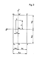
- the coordinate zero point is placed on half of the tooth width b / 2 on the generating roller axis in point W o (FIG. 3).
- the meshing distances g aO and g al on the tool rack on the pinion 1 are calculated according to the known formulas of the involute geometry.
- the generation engagement field is somewhat wider than the gear pairing engagement field g ⁇ > g ⁇ .
- the length EE ' creates the match.
- the position of a grinding point is given with the coordinates g and h.
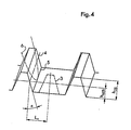
- a tool reference profile is used in a known manner to generate an involute surface using the rolling method. is won, cas is embodied, at the sub-level of which the workpiece rolls. Since cutting gear processing machines, especially gear grinding machines, generally have two working surfaces, which can be divided into two tools, in particular grinding wheels, or combined in one tool, two active flanks can be distinguished on the tool reference rack.
- the coordinate zero point in relation to the grinding stroke H and the rolling path W ' is chosen with regard to mathematical symmetry such that the symmetry point M o of both grinding wheels is centered on the wheel width and at this grinding stroke position in the In the middle of the total rolling path of both Schielfinr fall from 0074930 from this position, the grinding stroke is calculated upwards with a positive sign, downwards with a negative sign, the rolling path to the right with a positive sign and to the left with a negative sign.
- the one flank of the tool reference rack is shown in outline with the outline N'N "M” M '.
- This edge is not in the drawing plane. It is folded into the drawing plane and then has the outline N'N "[M"] [M '].
- the locating point P o for the grinding wheel in this flank is in the zero position of the grinding stroke and rolling path the base point of the normal from the rolling point W 0 to the tool rack flank. In any rolling and grinding stroke position, the locating point P o becomes the point P, which is then determined.
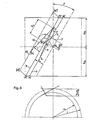
- the center of the circular circular edge of the plate-shaped grinding wheel lies on the vertical from the location point P to the foot line. The grinding edge always touches this foot line.
- the tool rack reference profile is designated in this figure with 7 and the partial line of the tool rack flank with 8.
- the base line of the tool rack flank has the reference symbol 9 and in its fold 10.
- the flank contact line between the rack flank and the wheel flank is denoted by 11 and the associated fold by 12.
- flank contact line T o C o passes through the point P o and runs from C in elevation T. In the fold it is the point [P o ] and the flank contact line runs from C to [T o ].
- the coordinates g and h of the locating point of the grinding wheel in the engagement field can be derived.
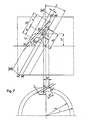
- the tool reference rod flank is shown in the drawing plane.
- the position of the flank contact line and the position of the edge of the grinding wheel are determined by the location point P.
- two grinding points on the flank contact line are determined by this grinding wheel edge, an outer grinding point P a and an inner grinding point P i .
- the grinding wheel edge (as mentioned above) is shown in the outline of the tool reference tooth flank.
- Reference 14 is used for the partial line and reference 15 for the bottom line, reference 16 for the flank contact line.
- the radius of the grinding wheel edge of the plate wheel is denoted by R s , the outer grinding point by P a and the inner grinding point by P i .
- the coordinates of the two grinding points in the engagement field are:
- rolling path values W and grinding stroke values H are continually used for EDP evaluation, from which coordinate values g and h are obtained in pairs for the two grinding points S a and S i (in the case of disc grinding wheels).
- an IT decision process is carried out as to whether and which amount of correction should be carried out via the grinding wheel axis.
- a correction is carried out when only one grinding point, namely the trailing point in the sense of traversing the intervention field, comes into effect. Since theoretically every grinding point comes across at all intervention field points, the possibility of correction is ensured.
- a variant of the grinding process which is the basis of these geo 007 4930 metric considerations, is the so-called surface grinding process (see also Fig. 15). Only the front grinding wheel edges work, which are brought closer to the tooth flanks by swiveling the wheel rear edges.
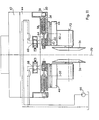
- the gear grinding machine shown in Fig.lo is set up for grinding the tooth flanks of a helical gear 19, the axis 20 of which is arranged vertically.
- the gear grinding machine includes a base 22 in which a rotary table 24 is mounted so as to be rotatable about the vertical axis 20.
- the wheel 19 is clamped on the rotary table 24 and exclusively carries out the rotary movements required for the partial grinding, namely rolling rotations, to which a partial rotation follows after grinding two tooth flanks.
- a bed slide 30 is guided so as to be adjustable radially to the wheel 19.
- a stand slide 32 is displaceably guided tangentially to the wheel 19 in order to give the grinding wheels 26 the linearly reciprocating components of the rolling movement.
- a stand 34 is fastened to the stand slide 32, on which a swivel guide 36 is mounted so as to be pivotable about a horizontal axis 38 normal to the wheel 19.
- An externally toothed ring segment 40 is arranged on the stand 34 for pivoting and locking the swivel guide 36.
- the pivot guide 36 is against the Vertical inclined by the helix angle ⁇ of the toothing of the wheel 19.
- a transverse guide 42 can be moved up and down in strokes along the swivel guide 36.
- a cross slide 44 is guided on the transverse guide 42 and carries two grinding supports 46. At each grinding support 46, one of the grinding wheels 26 is rotatably mounted; a drive motor 48 for the right grinding wheel 26 in FIGS. 10 and 11 can be seen in FIG.
- Each of the grinding supports 46 (FIG. 11) can be displaced with respect to the cross slide 44 in the direction of the axis 50 of the threaded spindle 54.
- the two grinding supports 46 can each be adjusted in angle by an axis 52 which is parallel to the swivel guide 36 in order to adapt to different pressure angles.
- a grinding spindle 54 is assigned to each grinding support 46, which is axially immovable in the cross slide 44 and can be driven by a motor 56.
- Each of the threaded spindles 54 is screwed into a nut part 58 which is displaceably guided parallel to the axis 50 with respect to the associated grinding support 46.
- a double-acting hydraulic cylinder 60 in which a piston 62 works, is attached to each grinding support 46_. The axis of the cylinder 60 is aligned with that of the associated threaded spindle 54.
- the piston 62 is connected to the nut part 58 by a piston rod 64.
- the two cylinders 60 are supplied with oil by a common pump 66 via a three-position valve 68; In the illustrated central position of these valves, the cylinder spaces formed on both sides of the associated piston 62 are cut off from the direct connection to the pump 66 in each of the two cylinders 60.
- the reference symbol 70 is used as the axis of symmetry for the two grinding supports 46.
- a variant of the device provides for the grinding wheels 26 to be displaced with respect to their grinding spindle axes 72.
- the two grinding wheels 26 operate with their essentially flat edge surfaces facing away from one another.
- Each of the two grinding wheels 26 is given the normal feed movements by the associated motor 56 via the spindle 54, the nut part 58, the piston rod 64 and the cylinder 60 without the piston 62 moving in the cylinder.
- the correction movements required for profile and / or longitudinal corrections are given to each grinding wheel 26 in that the associated cylinder 60 is supplied with oil on one or the other side of its piston 62.
- the rolling motion is broken down into a rotary and a translatory component.
- the rotation is determined by a partial wheel with a worm, the translation by the module spindle (see Fig. 10).
- Both drives are connected via change gears to generate the desired module and the desired number of teeth.
- the grinding feed is accomplished via a ram that moves up and down in a rotating part. This rotating part is inclined according to the bevel angle to be ground.
- the position of the geometric grinding points in the face cut (along the E volvente) and in section of the tooth flank with a cylinder coaxial to the wheel body (along the flank line) both from the rolling movement and at the same time from the lifting movement.
- the geometric grinding points are defined in the engagement field diagram (see Fig. 13), ie in the coordinate system wheel width b / engagement distance g ⁇ (rolling path or roll angle) and on the other hand in the coordinate system of the grinding machine, formed by grinding stroke position H and rolling path position W.
- a tooth flank is shown on the left, in which the generators and the two geometrical grinding points P a and P i are indicated, in which the grinding wheel touches the involute flank in a specific grinding stroke position and a specific rolling path position.
- the same picture is shown on the right, but in a right-angled coordinate system g ⁇ / b.
Landscapes
- Engineering & Computer Science (AREA)
- Mechanical Engineering (AREA)
- Grinding-Machine Dressing And Accessory Apparatuses (AREA)
- Finish Polishing, Edge Sharpening, And Grinding By Specific Grinding Devices (AREA)
- Micro-Organisms Or Cultivation Processes Thereof (AREA)
- Dental Tools And Instruments Or Auxiliary Dental Instruments (AREA)
Applications Claiming Priority (2)
| Application Number | Priority Date | Filing Date | Title |
|---|---|---|---|
| CH5921/81 | 1981-09-14 | ||
| CH5921/81A CH660462A5 (de) | 1981-09-14 | 1981-09-14 | Waelzverfahren zur spangebenden bearbeitung evolventenfoermiger zahnflanken mit profil- und laengskorrekturen. |
Publications (3)
| Publication Number | Publication Date |
|---|---|
| EP0074930A2 true EP0074930A2 (fr) | 1983-03-23 |
| EP0074930A3 EP0074930A3 (en) | 1983-07-27 |
| EP0074930B1 EP0074930B1 (fr) | 1986-01-02 |
Family
ID=4301550
Family Applications (1)
| Application Number | Title | Priority Date | Filing Date |
|---|---|---|---|
| EP82810386A Expired EP0074930B1 (fr) | 1981-09-14 | 1982-09-14 | Méthode générative pour l'usinage par enlèvement de copeaux de flancs de dents à denture en développante avec corrections du profil transversal et longitudinal |
Country Status (9)
| Country | Link |
|---|---|
| US (1) | US4467568A (fr) |
| EP (1) | EP0074930B1 (fr) |
| JP (1) | JPS5859729A (fr) |
| CH (1) | CH660462A5 (fr) |
| DD (1) | DD209475A1 (fr) |
| DE (2) | DE3142384A1 (fr) |
| FR (1) | FR2512713A1 (fr) |
| GB (1) | GB2106813B (fr) |
| IT (1) | IT1153566B (fr) |
Cited By (2)
| Publication number | Priority date | Publication date | Assignee | Title |
|---|---|---|---|---|
| EP0180747A3 (fr) * | 1984-11-03 | 1988-08-24 | Werkzeugmaschinenfabrik Oerlikon-Bührle AG | Procédé et dispositif pour la fabrication de flancs de dents sous forme d'arcs de développante de cercle |
| DE102010026412A1 (de) | 2010-07-07 | 2012-01-12 | Stoyan Radev | Verfahren zur Fertigung periodischer Zahnflankenmodifikationen, Werkzeugmaschine und computerlesbares Medium |
Families Citing this family (21)
| Publication number | Priority date | Publication date | Assignee | Title |
|---|---|---|---|---|
| CH658617A5 (de) * | 1982-12-24 | 1986-11-28 | Maag Zahnraeder & Maschinen Ag | Zahnflankenschleifmaschine mit doppelkegelfoermiger schleifscheibe. |
| CH665583A5 (de) * | 1983-07-08 | 1988-05-31 | Maag Zahnraeder & Maschinen Ag | Verfahren zum steuern der hubbewegung einer im teilwaelzverfahren arbeitenden zahnflankenschleifmaschine. |
| JPS6056821A (ja) * | 1983-09-09 | 1985-04-02 | Honda Motor Co Ltd | 歯車研削機 |
| CH662298A5 (de) * | 1983-10-18 | 1987-09-30 | Maag Zahnraeder & Maschinen Ag | Verfahren und anordnung zum beseitigen der zahnflankenwelligkeit auf zahnradproduktions- oder -messmaschinen. |
| US4631870A (en) * | 1985-03-28 | 1986-12-30 | Industrial Technology Research Institute | CNC grinding machine |
| US4833836A (en) * | 1987-07-31 | 1989-05-30 | Metal Industries Development Centre | Process for grinding a gear tooth blank to form an involute gear tooth |
| CH673800A5 (fr) * | 1988-03-08 | 1990-04-12 | Maag Zahnraeder & Maschinen Ag | |
| US5174699A (en) * | 1989-05-17 | 1992-12-29 | Hermann Pfauter Gmbh & Co. | Method for finishing gears via skiving |
| US5116173A (en) * | 1991-02-26 | 1992-05-26 | The Gleason Works | Method of generating bevel and hypoid gears |
| CH683970A5 (de) * | 1991-08-28 | 1994-06-30 | Reishauer Ag | Verfahren und Maschine zur Zahnradfeinbearbeitung. |
| DE502004008020D1 (de) * | 2004-04-06 | 2008-10-23 | Gleason Works | Verfahren zum Abrichten einer im wesentlichen zylindrischen Schleifschnecke |
| DE602007004003D1 (de) * | 2006-09-19 | 2010-02-04 | Gleason Works | Verfahren zur fertigung von kegelrädern zwecks herstellung einer diffusen oberflächenstruktur |
| DE102008063858A1 (de) * | 2008-12-19 | 2010-07-01 | Gebr. Heller Maschinenfabrik Gmbh | Werkzeugmaschine und Verfahren zur Herstellung von Verzahnungen |
| DE102012015846A1 (de) * | 2012-04-17 | 2013-10-17 | Liebherr-Verzahntechnik Gmbh | Verfahren und Vorrichtung zum Hartfeinbearbeiten von modifizierten Verzahnungen |
| JP5761577B2 (ja) * | 2012-06-22 | 2015-08-12 | アイシン精機株式会社 | クラウンギヤの製造装置及び製造方法 |
| US11022200B2 (en) | 2014-06-06 | 2021-06-01 | Delbert Tesar | Simplified parallel eccentric rotary actuator |
| US9623502B2 (en) * | 2014-11-07 | 2017-04-18 | Jtekt Corporation | Gear machining device and gear machining method |
| DE102015002362A1 (de) * | 2015-02-26 | 2016-09-01 | Liebherr-Verzahntechnik Gmbh | Bearbeitungskopf für eine Verzahnmaschine und Verfahren zur Verzahnung eines Werkstückes, insbesondere einer Schneckenwelle oder Zahnstange |
| US11166864B2 (en) | 2016-12-06 | 2021-11-09 | Delbert Tesar | Actuators for patient mobility devices, patient healthcare devices and human prosthetics |
| DE102021131998A1 (de) | 2021-12-03 | 2023-06-07 | Klingelnberg GmbH. | Verfahren zur schleifbearbeitung von kegelrädern |
| CN121607717B (zh) * | 2026-02-03 | 2026-06-02 | 湖南理工职业技术学院 | 一种复杂曲面齿轮的高精度加工方法 |
Family Cites Families (8)
| Publication number | Priority date | Publication date | Assignee | Title |
|---|---|---|---|---|
| DE1230650B (de) * | 1957-12-06 | 1966-12-15 | Maag Zahnraeder & Maschinen Ag | Einrichtung zur Erzeugung zusaetzlicher Relativbewegungen zwischen den beiden Schleifscheiben einer nach dem Waelzverfahren arbeitenden Zahnradschleifmaschine und dem Werkstueck |
| GB844207A (en) * | 1957-12-06 | 1960-08-10 | Maag Zahnraeder & Maschinen Ag | Improvements in or relating to gear grinding machines |
| DE2029359B1 (de) * | 1970-06-15 | 1971-12-09 | Hofler, Willy, Dr Ing , 7500 Karls | Vorrichtung zum Einstellen der Span abnähme beim Zweiweg Walzschleifen von Zahn radern |
| JPS5410755B1 (fr) * | 1970-10-16 | 1979-05-09 | ||
| CH560570A5 (fr) * | 1972-09-07 | 1975-04-15 | Maag Zahnraeder & Maschinen Ag | |
| DE2324683C3 (de) * | 1973-05-16 | 1978-12-21 | Zahnradfabrik Friedrichshafen Ag, 7990 Friedrichshafen | Korrektureinrichtung an einer Maschine zum Teilwälzschleifen von profilkorrigierten gerade- oder schräg vorverzahnten Stirnrädern |
| CH639305A5 (de) * | 1979-06-20 | 1983-11-15 | Maag Zahnraeder & Maschinen Ag | Teilwaelzverfahren und vorrichtung zum schleifen von verzahnungen mit evolventenfoermigem zahnflankenprofil. |
| CH649491A5 (de) * | 1981-04-27 | 1985-05-31 | Maag Zahnraeder & Maschinen Ag | Vorrichtung zum abrichten und nachstellen einer schleifscheibe an einer zahnflanken-schleifmaschine. |
-
1981
- 1981-09-14 CH CH5921/81A patent/CH660462A5/de not_active IP Right Cessation
- 1981-10-26 DE DE19813142384 patent/DE3142384A1/de not_active Ceased
-
1982
- 1982-08-30 IT IT23033/82A patent/IT1153566B/it active
- 1982-09-07 US US06/415,360 patent/US4467568A/en not_active Expired - Fee Related
- 1982-09-10 GB GB08225881A patent/GB2106813B/en not_active Expired
- 1982-09-13 DD DD82243204A patent/DD209475A1/de not_active IP Right Cessation
- 1982-09-14 DE DE8282810386T patent/DE3268304D1/de not_active Expired
- 1982-09-14 EP EP82810386A patent/EP0074930B1/fr not_active Expired
- 1982-09-14 FR FR8215521A patent/FR2512713A1/fr not_active Withdrawn
- 1982-09-14 JP JP57158981A patent/JPS5859729A/ja active Pending
Cited By (4)
| Publication number | Priority date | Publication date | Assignee | Title |
|---|---|---|---|---|
| EP0180747A3 (fr) * | 1984-11-03 | 1988-08-24 | Werkzeugmaschinenfabrik Oerlikon-Bührle AG | Procédé et dispositif pour la fabrication de flancs de dents sous forme d'arcs de développante de cercle |
| US4811528A (en) * | 1984-11-03 | 1989-03-14 | Werkzeugmaschinenfabrik Oerlikon-Buhrle Ag | Method for production of envolute gear tooth flanks |
| DE102010026412A1 (de) | 2010-07-07 | 2012-01-12 | Stoyan Radev | Verfahren zur Fertigung periodischer Zahnflankenmodifikationen, Werkzeugmaschine und computerlesbares Medium |
| WO2012003975A2 (fr) | 2010-07-07 | 2012-01-12 | Stoyan Radev | Procédé pour usiner des modifications périodiques de flancs de dents, machine-outil et support lisible par ordinateur |
Also Published As
| Publication number | Publication date |
|---|---|
| IT8223033A1 (it) | 1984-03-01 |
| GB2106813A (en) | 1983-04-20 |
| DE3268304D1 (en) | 1986-02-13 |
| IT8223033A0 (it) | 1982-08-30 |
| US4467568A (en) | 1984-08-28 |
| CH660462A5 (de) | 1987-04-30 |
| IT1153566B (it) | 1987-01-14 |
| FR2512713A1 (fr) | 1983-03-18 |
| DE3142384A1 (de) | 1983-04-14 |
| DD203836A5 (de) | 1983-11-09 |
| EP0074930B1 (fr) | 1986-01-02 |
| JPS5859729A (ja) | 1983-04-08 |
| GB2106813B (en) | 1985-05-22 |
| EP0074930A3 (en) | 1983-07-27 |
| DD209475A1 (de) | 1984-05-09 |
Similar Documents
| Publication | Publication Date | Title |
|---|---|---|
| EP0074930B1 (fr) | Méthode générative pour l'usinage par enlèvement de copeaux de flancs de dents à denture en développante avec corrections du profil transversal et longitudinal | |
| EP3556501B1 (fr) | Procédé de rectification de denture par génération d'une pièce de la roue dentée et machine de rectification dotée d'une commande de rectification de denture par génération d'une pièce de la roue dentée | |
| EP1987919B1 (fr) | Procédé et meuleuse destinés à profiler un outil de rectification | |
| DE3752009T3 (de) | Mehrfachachsenzahnradwälzmaschine zur herstellung von kegelrädern und hypoidrädern | |
| EP2412467B1 (fr) | Procédé de fraisage d'une dent de roue conique selon le procédé de fraisage continu | |
| EP3758876A1 (fr) | Outil de chanfreinage, système de chanfreinage, machine à tailler des dentures et procédé servant à chanfreiner des dentures | |
| EP2647459A1 (fr) | Dispositif et procédé de traitement de roues coniques utilisant un outil de rectification à mouvement excentrique | |
| DE102012008296A1 (de) | Vorrichtung und Verfahren zum Erzeugen, Bearbeiten und/oder Prüfen profiltragender Segmente | |
| EP3348354A1 (fr) | Procédé d'usinage de roues dentées coniques à l'aide d'une meule boisseau à mouvement excentrique pouvant être dressée | |
| DE3734828C1 (de) | Verfahren zum Teilwaelzschleifen von Zahnraedern sowie eine dafuer geeignete Maschine | |
| CH676099A5 (fr) | ||
| EP2851150B1 (fr) | Outil, procédé et machine destinés à fabriquer un profil denté sur une pièce par taillage des engrenages par développante | |
| EP0360953B1 (fr) | Machine pour la finition de flancs de dents de pièces dentées | |
| EP0022586B1 (fr) | Procédé pour rectifier le bombé des roues dentées à dents longitudinalement courbes et meule pour la mise en oeuvre du procédé | |
| DE3447389A1 (de) | Verfahren und einrichtung zur bearbeitung der zahnflanken eines rotierenden, verzahnten werkstuecks | |
| EP4028215B1 (fr) | Procédé de réalisation d'un rotor d'un compresseur à vis ou d'une pièce dotée d'un profil hélicoïdal | |
| DE2545565A1 (de) | Vorrichtung zur formung eines tragflaechenprofils | |
| DE2641745A1 (de) | Verfahren zur herstellung eines stirnzahnradpaares - verzahnungsmaschine zur durchfuehrung des verfahrens - stirnzahnradpaar hergestellt nach dem verfahren | |
| DE698149C (de) | Verfahren zum Schleifen von Kegelraedern mit geraden, in ihrer Laengsrichtung ballig geformten Zaehnen | |
| DE1295323B (de) | Maschine zum laengsballigen Verzahnen eines Kegel- bzw. Hypoidrades mit laengsgekruemmten Zaehnen | |
| DE19755359A1 (de) | Verfahren zum Herstellen einer Verzahnung nach dem Abwälzverfahren | |
| DE2258236B2 (de) | Maschine zum Balligbearbeiten von Zahnrädern | |
| DE2308990C3 (de) | Vorrichtung zum Fertigrollen von Stirnzahnrädern | |
| DE393184C (de) | Verfahren zur Herstellung von Schraubenkegelraedern | |
| DE1527086C3 (de) | Maschine zum Verzahnen eines Kegel- oder Hypoidzahnrades |
Legal Events
| Date | Code | Title | Description |
|---|---|---|---|
| PUAI | Public reference made under article 153(3) epc to a published international application that has entered the european phase |
Free format text: ORIGINAL CODE: 0009012 |
|
| AK | Designated contracting states |
Designated state(s): CH DE FR GB IT LI NL SE |
|
| PUAL | Search report despatched |
Free format text: ORIGINAL CODE: 0009013 |
|
| AK | Designated contracting states |
Designated state(s): CH DE FR GB IT LI NL SE |
|
| 17P | Request for examination filed |
Effective date: 19840111 |
|
| ITF | It: translation for a ep patent filed | ||
| GRAA | (expected) grant |
Free format text: ORIGINAL CODE: 0009210 |
|
| AK | Designated contracting states |
Designated state(s): CH DE FR GB IT LI NL SE |
|
| REF | Corresponds to: |
Ref document number: 3268304 Country of ref document: DE Date of ref document: 19860213 |
|
| ET | Fr: translation filed | ||
| PLBE | No opposition filed within time limit |
Free format text: ORIGINAL CODE: 0009261 |
|
| STAA | Information on the status of an ep patent application or granted ep patent |
Free format text: STATUS: NO OPPOSITION FILED WITHIN TIME LIMIT |
|
| 26N | No opposition filed | ||
| PGFP | Annual fee paid to national office [announced via postgrant information from national office to epo] |
Ref country code: FR Payment date: 19900806 Year of fee payment: 9 |
|
| PGFP | Annual fee paid to national office [announced via postgrant information from national office to epo] |
Ref country code: GB Payment date: 19900810 Year of fee payment: 9 |
|
| PGFP | Annual fee paid to national office [announced via postgrant information from national office to epo] |
Ref country code: CH Payment date: 19900815 Year of fee payment: 9 |
|
| PGFP | Annual fee paid to national office [announced via postgrant information from national office to epo] |
Ref country code: SE Payment date: 19900816 Year of fee payment: 9 |
|
| PGFP | Annual fee paid to national office [announced via postgrant information from national office to epo] |
Ref country code: DE Payment date: 19900829 Year of fee payment: 9 |
|
| ITTA | It: last paid annual fee | ||
| PGFP | Annual fee paid to national office [announced via postgrant information from national office to epo] |
Ref country code: NL Payment date: 19900930 Year of fee payment: 9 |
|
| PG25 | Lapsed in a contracting state [announced via postgrant information from national office to epo] |
Ref country code: GB Effective date: 19910914 |
|
| PG25 | Lapsed in a contracting state [announced via postgrant information from national office to epo] |
Ref country code: SE Effective date: 19910915 |
|
| PG25 | Lapsed in a contracting state [announced via postgrant information from national office to epo] |
Ref country code: LI Effective date: 19910930 Ref country code: CH Effective date: 19910930 |
|
| PG25 | Lapsed in a contracting state [announced via postgrant information from national office to epo] |
Ref country code: NL Effective date: 19920401 |
|
| GBPC | Gb: european patent ceased through non-payment of renewal fee | ||
| NLV4 | Nl: lapsed or anulled due to non-payment of the annual fee | ||
| PG25 | Lapsed in a contracting state [announced via postgrant information from national office to epo] |
Ref country code: FR Effective date: 19920529 |
|
| REG | Reference to a national code |
Ref country code: CH Ref legal event code: PL |
|
| PG25 | Lapsed in a contracting state [announced via postgrant information from national office to epo] |
Ref country code: DE Effective date: 19920602 |
|
| REG | Reference to a national code |
Ref country code: FR Ref legal event code: ST |
|
| EUG | Se: european patent has lapsed |
Ref document number: 82810386.1 Effective date: 19920408 |