EP0075105B1 - Einrichtung mit einem Lufttrockner für Druckluftanlagen - Google Patents
Einrichtung mit einem Lufttrockner für Druckluftanlagen Download PDFInfo
- Publication number
- EP0075105B1 EP0075105B1 EP82107312A EP82107312A EP0075105B1 EP 0075105 B1 EP0075105 B1 EP 0075105B1 EP 82107312 A EP82107312 A EP 82107312A EP 82107312 A EP82107312 A EP 82107312A EP 0075105 B1 EP0075105 B1 EP 0075105B1
- Authority
- EP
- European Patent Office
- Prior art keywords
- air
- valve
- chamber
- compressed
- arrangement according
- Prior art date
- Legal status (The legal status is an assumption and is not a legal conclusion. Google has not performed a legal analysis and makes no representation as to the accuracy of the status listed.)
- Expired
Links
- 239000008187 granular material Substances 0.000 claims description 12
- 239000012528 membrane Substances 0.000 claims description 10
- 238000001035 drying Methods 0.000 claims description 7
- 230000008878 coupling Effects 0.000 claims description 6
- 238000010168 coupling process Methods 0.000 claims description 6
- 238000005859 coupling reaction Methods 0.000 claims description 6
- 230000008929 regeneration Effects 0.000 claims description 3
- 238000011069 regeneration method Methods 0.000 claims description 3
- XLYOFNOQVPJJNP-UHFFFAOYSA-N water Substances O XLYOFNOQVPJJNP-UHFFFAOYSA-N 0.000 claims 1
- 238000009434 installation Methods 0.000 description 13
- 238000010586 diagram Methods 0.000 description 7
- 230000014759 maintenance of location Effects 0.000 description 5
- 238000012986 modification Methods 0.000 description 2
- 230000004048 modification Effects 0.000 description 2
- 230000006978 adaptation Effects 0.000 description 1
- 230000033228 biological regulation Effects 0.000 description 1
- 238000007664 blowing Methods 0.000 description 1
- 238000011109 contamination Methods 0.000 description 1
- 239000002274 desiccant Substances 0.000 description 1
- 238000011161 development Methods 0.000 description 1
- 230000018109 developmental process Effects 0.000 description 1
- 230000000694 effects Effects 0.000 description 1
- 230000007613 environmental effect Effects 0.000 description 1
- 238000004519 manufacturing process Methods 0.000 description 1
- 238000005259 measurement Methods 0.000 description 1
- 239000002245 particle Substances 0.000 description 1
- 230000001681 protective effect Effects 0.000 description 1
- 230000001105 regulatory effect Effects 0.000 description 1
- 230000002040 relaxant effect Effects 0.000 description 1
- 238000011144 upstream manufacturing Methods 0.000 description 1
Images


Classifications
-
- B—PERFORMING OPERATIONS; TRANSPORTING
- B60—VEHICLES IN GENERAL
- B60T—VEHICLE BRAKE CONTROL SYSTEMS OR PARTS THEREOF; BRAKE CONTROL SYSTEMS OR PARTS THEREOF, IN GENERAL; ARRANGEMENT OF BRAKING ELEMENTS ON VEHICLES IN GENERAL; PORTABLE DEVICES FOR PREVENTING UNWANTED MOVEMENT OF VEHICLES; VEHICLE MODIFICATIONS TO FACILITATE COOLING OF BRAKES
- B60T17/00—Component parts, details, or accessories of power brake systems not covered by groups B60T8/00, B60T13/00 or B60T15/00, or presenting other characteristic features
- B60T17/002—Air treatment devices
- B60T17/004—Draining and drying devices
-
- B—PERFORMING OPERATIONS; TRANSPORTING
- B01—PHYSICAL OR CHEMICAL PROCESSES OR APPARATUS IN GENERAL
- B01D—SEPARATION
- B01D53/00—Separation of gases or vapours; Recovering vapours of volatile solvents from gases; Chemical or biological purification of waste gases, e.g. engine exhaust gases, smoke, fumes, flue gases, aerosols
- B01D53/26—Drying gases or vapours
- B01D53/261—Drying gases or vapours by adsorption
-
- B—PERFORMING OPERATIONS; TRANSPORTING
- B60—VEHICLES IN GENERAL
- B60T—VEHICLE BRAKE CONTROL SYSTEMS OR PARTS THEREOF; BRAKE CONTROL SYSTEMS OR PARTS THEREOF, IN GENERAL; ARRANGEMENT OF BRAKING ELEMENTS ON VEHICLES IN GENERAL; PORTABLE DEVICES FOR PREVENTING UNWANTED MOVEMENT OF VEHICLES; VEHICLE MODIFICATIONS TO FACILITATE COOLING OF BRAKES
- B60T15/00—Construction arrangement, or operation of valves incorporated in power brake systems and not covered by groups B60T11/00 or B60T13/00
- B60T15/02—Application and release valves
- B60T15/36—Other control devices or valves characterised by definite functions
Definitions
- the invention relates to a device with an air dryer for compressed air systems, in particular for compressed air braking systems, according to the preamble of claim 1.
- a device of this type consisting of an air dryer and a switching and control device is previously known from DE-U-8 008 352, this known device in a compressed air system consisting of a compressed air generator (air compressor), a compressed air reservoir (storage container) and a pressure regulator is arranged in the pipes leading from the air compressor to the storage container.
- a compressed air generator air compressor
- a compressed air reservoir storage container
- a pressure regulator is arranged in the pipes leading from the air compressor to the storage container.
- the switching and control device of the device mentioned contains a check valve bridged by a nozzle and a pressure switch designed as a two-point controller for the changeover times, a shut-off valve being arranged in the line of the nozzle bridging the check valve, the control period of which can be controlled by means of a pneumatic delay device is.
- the measurements of the drying process or the blowing out of the condensate from the desiccant, measured in time periods, require e.g. B. in vehicles with compressed air braking systems, the different vehicle types or the different operating conditions of the vehicles adapted modifications of facilities with air dryers, for example due to different operating pressures in the compressed air systems or different volumes of the compressed air tank.
- the known device with the air dryer i. H. in particular, the time control should be designed for the worst case, which leads to excessive air consumption in all other cases.
- Another problem with this device arises from the use of the nozzle, since an exact adjustment of the time period can only be achieved with a small nozzle, which, however, entails the great risk of clogging by dirt particles.
- the invention is therefore based on the object of providing a device of the type mentioned at the outset which can be used for all conditions of use, so that the production of several modifications is dispensed with.
- the facility is also said to be insensitive to contamination.
- the regeneration of the dry granulate begins immediately by returning dried air from the vehicle's boiler system. This backflow continues until the pressure in the system has dropped by a certain predetermined value, which is required for drying the granules.
- the pressure range is independent of the boiler volume of the vehicle system and therefore it does not matter whether the vehicle is used in solo or trailer operation.
- the desired pressure drop is achieved in the device according to the invention by specifying a pressure difference between two chambers connected by check valves. The arrangement of the check valves ensures that changes in the switch-off height of the pressure regulator have no influence on the pressure drop.
- the pressure regulator can be arranged in the line from the air compressor to the consumer (pressure regulator principle) or parallel to this line (governor principle).
- Advantageous developments and refinements of the invention can be found in the subclaims, the arrangement of the device according to the invention being provided in a trailer vehicle according to subclaim 15.
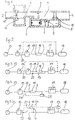
- FIG. 10 shows an installation diagram of the switching and control device according to FIG. 1 in a two-line compressed air brake system of an appendix vehicle.
- Fig. 1 shows a switching and control device for an air dryer, which is arranged according to the installation schemes shown in Figs. 2, 3, 4 and 5 in the line leading from the air dryer to the consumer.
- the housing 1 of the switching and control device has a first connection 2 which is connected on the one hand to the air dryer and on the other hand to a first compressed air chamber 3 and via a second connection 4 which is connected on the one hand to the consumer and on the other hand to a second compressed air chamber 5 .
- a shut-off valve 6, 7, which can be actuated by a valve piston 6, is arranged between the first compressed air chamber 3 and the second compressed air chamber 5, a housing web forming the valve seat 7.
- the valve piston 6 can be acted upon by the pressure in the first compressed air chamber 3 in the opening direction of the shut-off valve 6, 7, while the pressure of a control chamber 8 can be applied to the valve piston 6 in the closing direction of the shut-off valve 6, 7.
- the control chamber 8 is connected to the second compressed air chamber 5 via a first and a second check valve 9, 10 such that the first check valve 9 connects the second compressed air chamber 5 into the control chamber 8 and the second check valve 10 connects the control chamber 8 in produce the second compressed air chamber 5.
- a third check valve 11 which opens in the direction of the second connection 4, is arranged with a throttle bore 12.
- the compressed air conveyed by the air compressor 13 flows via a pressure regulator 14, an air dryer 15, the connections 2 and 4 of the switching and control device 16 and via a multi-circuit protection valve 17 into a storage container 18.
- the switching and control device 16 in this exemplary embodiment is in the main line 19 switched.
- the check valve 11 and the piston 6 or the valve 6, 7 are in the open position during the load run of the air compressor 13. Air flows from the second compressed air chamber 5 into the control chamber 8 via the first check valve 9, which has a specific retention pressure (e.g. 0.3 bar).
- the piston 6 or the shut-off valve 6, 7 closes and a further backflow of compressed air from the reservoir 18 to the air dryer 15 is prevented.
- the pressure in the reservoir 18 now only drops as a result of consumption by the connected consumers (for example when the brake is actuated).
- a certain pressure difference between the second compressed air chamber 5 and the control chamber 8 eg 0.2 bar
- the drain valve in the air dryer 15 is closed via the line 20.
- the piston 6 shown can also be a membrane piston.
- FIG. 3 shows the arrangement of the switching and control device 16 according to FIG. 1 in a secondary line 21 running parallel to the main line 19. Since only a partial air flow flows through the housing of the switching and control device 16, the nominal diameter of the flow cross section can be smaller being held. In this system, the installation of a check valve 22 in the main line 19 is necessary in order to prevent backflow past the switching and control device 16.
- FIG. 4 represents a system regulated by means of a pressure regulator (governor) 23 via a line 24, the switching and control device 16 according to FIG. 1 being arranged in the main line 19.
- the controller 23 causes, in a manner not shown, that the air compressor is controlled by the pressure in the consumer system or in the reservoir 18.
- the installation diagram shown in FIG. 5 shows a system with pressure regulation and with a switching and control device 16 according to FIG. 1 arranged in a secondary line 2.
- the regulator 23 is located behind the multi-circuit protection valve 17, while in the 4 of the controller 23 is connected upstream of the multi-circuit protection valve 17. This different arrangement in the system's consumer circuit is irrelevant.
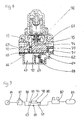
- the switching and control device for an air dryer shown in FIG. 6 is arranged in the installation diagram shown in FIG. 7 in a line leading from the air dryer to the consumer.
- the housing 31 of the switching and control device has a first connection 32 which is connected on the one hand to the air dryer and on the other hand to a first compressed air chamber 33 and via a second connection 34 which is connected on the one hand to the consumer and on the other hand to a second compressed air chamber 35.
- a shut-off valve 36, 37 which can be actuated by a membrane piston 36, is arranged between the first compressed air chamber 33 and the second compressed air chamber 35, a housing web forming the valve seat 37.
- the diaphragm piston 36 can be acted upon by the pressure in the first compressed air chamber 33 in the opening direction of the shut-off valve 36, 37, while the pressure of a first control chamber 38 can act on the diaphragm piston in the closing direction of the shut-off valve 36, 37.
- the first control chamber 38 is connected to a second control chamber 39 via a first and a second check valve 40 and 41 such that the first check valve 40 connects the second control chamber 39 to the first control chamber 38 and the second check valve 41 connects the first Establish the control chamber 38 in the second control chamber 39, the second control chamber 39 having a third connection 42.
- a throttle 43 is arranged between the first connection 32 and the first compressed air chamber 33.
- the compressed air conveyed by the air compressor 44 flows via a pressure regulator 45, an air dryer 46, a check valve 48 connected into the main line 47 and via a multi-circuit protection valve 49 into a storage container 50.
- a secondary line 51 which is parallel to the the air dryer 46 and that Protective valve 49 connecting main line 47, a partial air flow simultaneously flows through the switching and control device 52, the shut-off valve 36, 37 is in the open position.
- the open position of the shut-off valve 36, 37 is ensured by the fact that the pressure above the membrane piston 36 is lower than the pressure of the conveyed air below the membrane piston 36.
- the drain valve of the air dryer 46 receives an opening pulse via a line 53.
- the corresponding opening impulse reaches the second control chamber 39 via a line 54 and the third connection 42 of the switching and control device 52.
- This pressure which builds up in the second control chamber 39 opens the first check valve 40 and air flows into the first control chamber 38. Since the check valve 40 has a certain retention pressure (eg 0.3 bar), this pressure difference now prevails between the first compressed air chamber 33 and the first control chamber 38 so that the air can flow back from the second compressed air chamber 35 into the first compressed air chamber 33 and further to the air dryer 46 until there is a pressure equilibrium between the compressed air chambers 33, 35 and the first control chamber 38 and the diaphragm piston 36 the valve seat 37 touches down.
- the retention pressure of the second check valve 41 must be at least so great that air flows back from the first control chamber 38 into the second control chamber 39 only when the diaphragm piston 36 has sealed the shut-off valve 36, 37 exactly.
- the retention pressure of the second check valve 41 can be selected to be relatively high, thereby avoiding the risk of leaks at this valve.
- FIG. 8 shows a switching and control device which forms a structural unit with a pressure regulator (governor).
- a first control chamber 63 and a second control chamber 64 are arranged in a housing 62 flanged to the housing 61 of the controller, a membrane piston 65 being located between the two housings 61 and 62.
- This membrane piston 65 forms the shut-off valve 65, 66 with a housing web 66 of the housing 61.
- the connection of the two control chambers 63 and 64 is also established here by means of a first check valve 67 opening in the first control chamber 63 and by means of a second one in the second control chamber 64 opening check valve 68 made.
- the housing 61 has a first connection 69, which is connected on the one hand according to FIGS. 9 and 10 to the air dryer and on the other hand to a first compressed air chamber 70 and via a second connection 71 which on the one hand to the consumer and on the other hand to a second compressed air chamber 72 in Connection is established.
- the shut-off valve 65, 66 is also located in this structural unit between the first and second compressed air chambers 70 and 72.
- a throttle 73 is arranged between the first connection 69 and the first compressed air chamber 70.
- the diaphragm piston 65 can be acted upon by the pressure in the compressed air chambers 70, 72 in the opening direction of the shut-off valve 65, 66. while the pressure of the first control chamber 63 can be applied to the diaphragm piston 65 in the closing direction of the shut-off valve 65, 66.
- a third connection 74 of the housing 61 is connected on the one hand via a housing bore 75 to the shut-off valve 76 of the controller and on the other hand is connected to the second control chamber 64 via a housing bore 77.
- the pressure regulator (governor) / switching and control device unit is identified by item 78.
- the structural unit 78 is connected to a secondary line 79 to the main line 80 between the air dryer 81 and the multi-circuit protection valve 82 and the storage container 83 connected to it.
- a control line 86 connects the third connection 74 of the unit 78 to the air dryer 81.
- the air compressor 84 and the check valve 85 of the main line 80 should also be mentioned.
- the pressure in the first control chamber 63 is lower than the pressure in the compressed air chambers 70, 72 and the air can flow unhindered via the first connection 69, the throttle 73, the shut-off valve 65, 66 and the second connection 71 .
- a pressure pulse is passed to the air dryer 81 via the bore 75 and the third connection 74 in order to open its drain valve, this pressure pulse building up a pressure in the second control chamber 64 via the housing bore 77. Air flows from chamber 64 into first control chamber 63 via first check valve 67.
- the other function corresponds to the manner described in FIG. 6.
- the level of the retention pressure of the first check valve 9, 40, 67 can be made adjustable in order to make it possible to improve the drying effect in the event of changed environmental or operating conditions in order to achieve a lower dew point of the useful air.
- the switching and control device according to the invention can also be arranged in an advantageous manner in the trailer braking system, so that in addition to the regeneration of the granules of the air dryer installed in the towing vehicle, a proportion of dry air can be removed from the storage container of the trailer vehicle.
- the two-line air brake system of a trailer vehicle with a trailer supply line 90, 90a and a trailer brake line 91 is connected to the towing vehicle braking system via coupling heads 92 and 93 with coupling heads (not shown) of the towing vehicle.
- the trailer supply line 90 leads via a trailer brake valve 94 to a reservoir 95, the trailer brake valve 94 for actuating the wheel brakes of the trailer vehicle being controllable via a control connection of pressure pulses in the trailer brake line 91, by means of the pressure pulses providing a connection between the Reservoir 95 to line 90a leading to trailer brake valve 94 and a line 96 leading from trailer brake valve 94 to wheel brake cylinders, not shown, is produced.
- the switching and control device designated here as in FIGS. 2 to 5 with the position number 16 is connected with its connections 2 and 4 to a line 97 which bypasses the trailer brake valve 94 and runs parallel to the supply line 90, 90a.
- a bypass line 97 is provided here because the trailer brake valve 94 contains devices which are intended to prevent the compressed air from flowing back from the storage container 95 into the line 90 leading to the trailer supply coupling 92.
- a check valve the arrangement of which in the towing vehicle is necessary in the case of a switching and control device arranged in a parallel line in the main line, can therefore be dispensed with in the trailer vehicle.
- the trailer brake valve 94 has a manually actuated release valve 98.
- dry air not only flows from the towing vehicle's storage container through the switching and control device of the towing vehicle to the air dryer, but also dry air from the trailer's storage container 95 via the bypass line 97, the switching and control device 16, the supply line 90, the trailer supply coupling 92 and the line connection of the towing vehicle brake system which continues in the towing vehicle to the air dryer.
Landscapes
- Engineering & Computer Science (AREA)
- Chemical & Material Sciences (AREA)
- Transportation (AREA)
- Mechanical Engineering (AREA)
- Analytical Chemistry (AREA)
- General Chemical & Material Sciences (AREA)
- Oil, Petroleum & Natural Gas (AREA)
- Chemical Kinetics & Catalysis (AREA)
- Valves And Accessory Devices For Braking Systems (AREA)
- Drying Of Gases (AREA)
Description
- Die Erfindung betrifft eine Einrichtung mit einem Lufttrockner für Druckluftanlagen, insbesondere für Druckluft-Bremsanlagen, gemäß dem Oberbegriff des Anspruchs 1.
- Eine aus einem Lufttrockner und einer Schalt-und Steuereinrichtung bestehende Einrichtung dieser Art, ist durch die DE-U-8 008 352 vorbekannt, wobei diese bekannte Einrichtung in einer aus einem Drucklufterzeuger (Luftpresser), einem Druckluftspeicher (Vorratsbehälter) und einem Druckregler bestehenden Druckluftanlage in die vom Luftpresser zum Vorratsbehälter führenden Rohrleitungen angeordnet ist.
- Zur Regeneration des Trockengranulates im Lufttrockner wird bei dieser bekannten Einrichtung während der Abschaltphase des Druckreglers ein Teil der während der Lastphase getrockneten Luft im entspannten Zustand durch das Granulat ins Freie geleitet. Diese Luftmenge darf nicht zu gering sein, da sonst das Granulat nicht ausreichend regeneriert wird. Andererseits sollte diese Luftmenge jedoch nicht zu groß sein, da sonst die Einschaltdauer des Luftpressers zu groß wäre.
- Zur Lösung dieses Problems enthält die Schalt- und Steuereinrichtung der erwähnten Einrichtung ein von einer Düse überbrücktes Rückschlagventil sowie einen als Zweipunktregler für die Umschaltzeitpunkte ausgebildeten Druckwächter, wobei in der Leitung der das Rückschlagventil überbrückenden Düse ein Absperrventil angeordnet ist, dessen Steuerzeitspanne mittels einer pneumatischen Verzögerungseinrichtung steuerbar ist.
- Die in Zeitspannen gemessenen Einschaltungen des Trockenvorganges bzw. des Ausblasens des Kondensates aus dem Trockenmittel erfordern, z. B. bei Fahrzeugen mit Druckluft-Bremsanlagen, den verschiedenen Fahrzeugtypen bzw. den verschiedenen Einsatzbedingungen der Fahrzeuge angepaßte Abwandlungen von Einrichtungen mit Lufttrocknern, beispielsweise infolge unterschiedlicher Betriebsdrücke in den Druckluftanlagen oder unterschiedlicher Volumina der Druckluftbehälter.
- Bei Fahrzeugen, welche sowohl für den Solobetrieb als auch für den Anhängerbetrieb eingesetzt werden, muß die bekannte Einrichtung mit dem Lufttrockner, d. h. insbesondere die Zeitregelung für den ungünstigsten Fall ausgelegt sein, was bei allen anderen Fällen zu einem zu großen Luftverbrauch führt. Ein weiteres Problem bei dieser Einrichtung entsteht durch die Verwendung der Düse, da eine genaue Einstellung der Zeitspanne nur mit einer kleinen Düse realisierbar ist, was jedoch die große Gefahr einer Verstopfung durch Schmutzteilchen in sich birgt.
- Der Erfindung liegt deshalb die Aufgabe zugrunde, eine Einrichtung der eingangs erwähnten Art zu schaffen, welche für alle Einsatzbedingungen verwendbar ist, so daß die Herstellung von mehreren Abwandlungen entfällt. Die Einrichtung soll außerdem unempfindlich gegen Verschmutzung sein.
- Diese Aufgabe wird durch die im Patentanspruch 1 aufgeführte Erfindung gelöst.
- Im Moment des Umschaltens des Kompressors von Last- auf Leerlauf durch den Druckregler beginnt sofort das Regenerieren des Trockengranulates durch Rückströmen von getrockneter Luft aus der Fahrzeugkesselanlage. Dieses Rückströmen dauert so lange, bis der Druck in der Anlage um einen bestimmten - zum Trocknen des Granulates erforderlichen - vorgegebenen Wert abgefallen ist. Die Druckspanne ist dabei unabhängig von dem Kesselvolumen der Fahrzeuganlage und deshalb spielt es keine Rolle, ob das Fahrzeug im Solo- oder Anhängerbetrieb eingesetzt wird. Die gewünschte Druckabsenkung wird bei der erfindungsgemäßen Einrichtung durch Vorgabe einer sich zwischen zwei durch Rückschlagventile verbundenen Kammern einstellenden Druckdifferenz erreicht. Durch die Anordnung der Rückschlagventile wird erreicht, daß Änderungen in der Abschalthöhe des Druckreglers keinen Einfluß auf die Druckabsenkung haben.
- Der Druckregler kann in der Leitung von Luftpresser zum Verbraucher (Druckreglerprinzip) oder parallel zu dieser Leitung (Governorprinzip) angeordnet sein. Vorteilhafte Weiterbildungen und Ausgestaltungen der Erfindung sind den Unteransprüchen zu entnehmen, wobei gemäß Unteranspruch 15 die Anordnung der erfindungsgemäßen Einrichtung in einem Anhängefahrzeug vorgesehen ist.
- Die Erfindung wird nachfolgend an Hand von Ausführungsbeispielen, welche in der Zeichnung dargestellt sind, näher erläutert.
- Es zeigt
- Fig. 1 eine kolbengesteuerte Schalt- und Steuereinrichtung für einen Lufttrockner,
- Fig. 2 ein Einbauschema der Schalt- und Steuereinrichtung gemäß Fig. 1 (Anlage mit Druckregler),
- Fig. 3wie Fig. 2, jedoch Einbau der Schalt- und Steuereinrichtung in einer Parallelleitung,
- Fig. 4 wie Fig. 2 (Anlage mit einem Druckregler),
- Fig. 5 eine Anlagen-Kombination der Anlagen gemäß der Fig. 3 und 4,
- Fig. 6 eine membrangesteuerte Schalt- und Steuereinrichtung für einen Lufttrockner mit Steueranschluß für einen Druckregler nach dem Druckregler - oder dem Governorprinzip.
- Fig. 7 ein Einbauschema der Schalt- udn Steuereinrichtung gemäß Fig. 6,
- Fig. 8 eine an einen Druckregler angeflanschte membrangesteuerte Schalt- und Steuereinrichtung für einen Lufttrockner,
- Fig. 9 ein Einbauschema der Schalt- und Steuereinrichtung gemäß Fig. 8 und
- Fig. 10 ein Einbauschema der Schalt- und Steuereinrichtung gemäß Fig. 1 in einer Zweileitungs-Druckluftbremsanlage eines Anhängefahrzeugs.
- Die Fig. 1 stellt eine Schalt- und Steuereinrichtung für einen Lufttrockner dar, welche gemäß den in den Fig. 2, 3, 4 und 5 dargestellten Einbauschemata in der vom Lufttrockner zum Verbraucher führenden Leitung angeordnet ist. Das Gehäuse 1 der Schalt- und Steuereinrichtung verfügt über einen ersten Anschluß 2, der einerseits mit dem Lufttrockner und andererseits mit einer ersten Druckluftkammer 3 verbunden ist und über einen zweiten Anschluß 4 der einerseits mit dem Verbraucher und andererseits mit einer zweiten Druckluftkammer 5 in Verbindung steht. Zwischen der ersten Druckluftkammer 3 und der zweiten Druckluftkammer 5 ist ein von einem Ventilkolben 6 betätigbares Absperrventil 6, 7 angeordnet, wobei ein Gehäusesteg den Ventilsitz 7 bildet.
- Der Ventilkolben 6 ist in Öffnungsrichtung des Absperrventils 6, 7 von dem Druck in der ersten Druckluftkammer 3 beaufschlagbar, während die Beaufschlagung des Ventilkolbens 6 in die Schließrichtung des Absperrventils 6, 7 von dem Druck einer Steuerkammer 8 beaufschlagbar ist. Die Steuerkammer 8 ist mit der zweiten Druckluftkammer 5 über ein erstes und ein zweites Rückschlagventil 9,10 derart verbunden, daß das erste Rückschlagventil 9 eine Verbindung von der zweiten Druckluftkammer 5 in die Steuerkammer 8 und das zweite Rückschlagventil 10 eine Verbindung von der Steuerkammer 8 in die zweite Druckluftkammer 5 herstellen.
- Zwischen dem ersten Anschluß 2 und der ersten Druckluftkammer 3 ist ein sich in Richtung zweiter Anschluß 4 öffnendes drittes Rückschlagventil 11 mit einer Drosselbohrung 12 angeordnet.
- Die Funktion der Schalt- und Steuereinrichtung gemäß Fig. 1 wird nachfolgend unter Hinzuziehung des in Fig. 2 dargestellten Einbauschemas wie folgt beschrieben.
- Die vom Luftpresser 13 geförderte Druckluft strömt über einen Druckregler 14, einen Lufttrockner 15, die Anschlüsse 2 und 4 der Schalt-und Steuereinrichtung 16 und über ein Mehrkreisschutzventil 17 in einen Vorratsbehälter 18. Die Schalt- und Steuereinrichtung 16 ist bei diesem Ausführungsbeispiel in die Hauptleitung 19 geschaltet. Das Rückschlagventil 11 und der Kolben 6 bzw. das Ventil 6, 7 sind während des Lastlaufes des Luftpressers 13 in Offenstellung. Über das erste Rückschlagventil 9, welches einen bestimmten Rückhaltedruck hat (z. B. 0,3 bar) strömt dabei Luft von der zweiten Druckluftkammer 5 in die Steuerkammer 8.
- In dem Moment, in dem der Druckregler 14 bei Erreichen eines vorgegebenen Behälterdruckes den Luftpresser 13 in nicht dargestellter Weise auf Leerlauf schaltet, wird vom Druckregler 14 über eine Leitung 20 im Lufttrockner 15 ein Ablaßventil geöffnet und die unter Druck stehende Luft im Vorratsbehälter 18 beginnt durch die Schalt- und Steuereinrichtung 16 hindurch zum Lufttrockner 15 zurückzuströmen. Beim Passieren der Drosselbohrung 12 im Rückschlagventil 11 entspannt die Luft und kann infolge ihres großen Volumens das Granulat trocknen (regenerieren). Dabei sinkt der Druck in der zweiten Druckluftkammer 5, während der Druck in der Steuerkammer 8 zunächst unverändert bleibt. In dem Moment, in dem der Druck in der zweiten Druckluftkammer 5 kleiner wird als der Druck in der Steuerkammer 8 schließt der Kolben 6 bzw. das Absperrventil 6, 7 und ein weiteres Zurückströmen von Druckluft aus dem Vorratsbehälter 18 zum Lufttrockner 15 ist unterbunden. Der Druck im Vorratsbehälter 18 sinkt nunmehr nur noch infolge Verbrauches durch die angeschlossenen Verbraucher (z. B. bei einer Bremsbetätigung). Ab einer bestimmten Druckdifferenz zwischen der zweiten Druckluftkammer 5 und der Steuerkammer 8 (z. B. 0,2 bar) strömt Luft aus der Steuerkammer 8 durch das sich öffnende Rückschlagventil 10 in die zweite Druckluftkammer 5. Dadurch reduziert sich der Druck in der Steuerkammer 8, so daß beim nächsten Lastlauf eine Anpassung an einen evtl. geänderten Abschaltdruck des Druckreglers erfolgen kann. Nach dem Umschalten des Luftpressers 13 durch den Druckregler 14 auf Lastlauf wird über die Leitung 20 das erwähnte Ablaßventil im Lufttrockner 15 geschlossen.
- Der dargestellte Kolben 6 kann auch ein Membrankolben sein.
- Das Einbauschema gemäß Fig. 3 zeigt die Anordnung der Schalt- und Steuereinrichtung 16 gemäß Fig. 1 in einer parallel zur Hauptleitung 19 geführten Nebenleitung 21. Da hier nur ein Teilluftstrom das Gehäuse der Schalt- und Steuereinrichtung 16 durchströmt, kann die Nennweite des Durchflußquerschnittes kleiner gehalten werden. Bei dieser Anlage ist der Einbau eines Rückschlagventils 22 in der Hauptleitung 19 erforderlich, um eine Rückströmung an der Schalt-und Steuereinrichtung 16 vorbei zu verhindern.
- Das Einbauschema gemäß Fig. 4 stellt eine mittels eines Druckreglers (Governor) 23 über eine Leitung 24 geregelte Anlage dar, wobei die Schalt- und Steuereinrichtung 16 gemäß Fig. 1 in der Hauptleitung 19 angeordnet ist. Der Regler 23 bewirkt in nicht dargestellter Weise, daß der Luftpresser vom Druck in der Verbraucheranlage bzw. im Vorratsbehälter 18 gesteuert wird. Das in Fig. 5 dargestellte Einbauschema zeigt eine Anlage mit Druck-Regelung und mit einer in einer Nebenleitung 2 angeordneten Schalt- und Steuereinrichtung 16 gemäß Fig. 1. Bei dieser Anlage befindet sich der Regler 23 hinter dem Mehrkreis-Schutzventil 17, während in der Anlage gemäß Fig. 4 der Regler 23 vor das Mehrkreis-Schutzventil 17 geschaltet ist. Diese unterschiedliche Anordnung Im Verbraucherkreis der Anlage ist ohne Bedeutung.
- Die in Fig. 6 dargestellte Schalt- und Steuereinrichtung für einen Lufttrockner ist in dem in Fig. 7 dargestellten Einbauschema in einer vom Lufttrockner zum Verbraucher führenden Leitung angeordnet.
- Das Gehäuse 31 der Schalt- und Steuereinrichtung verfügt über einen ersten Anschluß 32 der einerseits mit dem Lufttrockner und andererseits mit einer ersten Druckluftkammer 33 verbunden ist und über einen zweiten Anschluß 34 der einerseits mit dem Verbraucher und andererseits mit einer zweiten Druckluftkammer 35 in Verbindung steht. Zwischen der ersten Druckluftkammer 33 und der zweiten Druckluftkammer 35 ist ein von einem Membrankolben 36 betätigbares Absperrventil 36, 37 angeordnet, wobei ein Gehäusesteg den Ventilsitz 37 bildet.
- Der Membrankolben 36 ist in Öffnungsrichtung des Absperrventils 36, 37 von dem Druck in der ersten Druckluftkammer 33 beaufschlagbar, während die Beaufschlagung des Membrankolbens in die Schließrichtung des Absperrventils 36, 37 von dem Druck einer ersten Steuerkammer 38 beaufschlagbar ist. Die erste Steuerkammer 38 ist mit einer zweiten Steuerkammer 39 über ein erstes und ein zweites Rückschlagventil 40 und 41 derart verbunden, daß das erste Rückschlagventil 40 eine Verbindung von der zweiten Steuerkammer 39 in die erste Steuerkammer 38 und das zweite Rückschlagventil 41 eine Verbindung von der ersten Steuerkammer 38 in die zweite Steuerkammer 39 herstellen, wobei die zweite Steuerkammer 39 einen dritten Anschluß 42 besitzt.
- Zwischen dem ersten Anschluß 32 und der ersten Druckluftkammer 33 ist eine Drossel 43 angeordnet.
- Die Funktion der Schalt- und Steuereinrichtung gemäß Fig. 6 wird nachfolgend unter Hinzuziehung des in Fig. 7 dargestellten Einbauschemas wie folgt beschrieben.
- Die vom Luftpresser 44 geförderte Druckluft strömt über einen Druckregler 45, einen Lufttrockner 46, ein in die Hauptleitung 47 geschaltetes Rückschlagventil 48 und über ein Mehrkreis-Schutzventil 49 in einen Vorratsbehälter 50. Über eine Nebenleitung 51, welche parallel zu der den Lufttrockner 46 und das Schutzventil 49 verbindenden Hauptleitung 47 verläuft, strömt gleichzeitig ein Teilluftstrom durch die Schalt- und Steuereinrichtung 52, deren Absperrventil 36, 37 sich in Offenstellung befindet. Die Offenstellung des Absperrventils 36, 37 ist dadurch sichergestellt, daß der Druck oberhalb des Membrankolbens 36 niedriger ist, als der Druck der geförderten Luft unterhalb des Membrankolbens 36.
- In dem Moment, in dem der Druckregler45 auf Leerlauf schaltet, bekommt das Ablaßventil des Lufttrockners 46 über eine Leitung 53 einen Öffnungsimpuls.
- Die Druckluft strömt nunmehr, sich über die Drossel 43 entspannend, zum Lufttrockner 46 zurück, regeneriert beim Durchströmen das Trocknungsgranulat und tritt über das Ablaßventil ins Freie.
- Gleichzeitig mit dem Öffnen des Ablaßventils des Lufttrockners 46 gelangt der entsprechende Öffnungsimpuls über eine Leitung 54 und den dritten Anschluß 42 der Schalt- und Steuereinrichtung 52 in deren zweite Steuerkammer 39.
- Dieser in der zweiten Steuerkammer 39 sich aufbauende Druck öffnet das erste Rückschlagventil 40 und Luft strömt in die erste Steuerkammer 38. Da das Rückschlagventil 40 einen bestimmten Rückhaltedruck (z. B. 0,3 bar) hat, herrscht diese Druckdifferenz nunmehr zwischen der ersten Druckluftkammer 33 und der ersten Steuerkammer 38, so daß die Luft aus der zweiten Druckluftkammer 35 in die erste Druckluftkammer 33 und weiter zum Lufttrockner 46 solange zurückströmen kann, bis ein Druckgleichgewicht zwischen den Druckluftkammern 33, 35 und der ersten Steuerkammer 38 herrscht und der Membrankolben 36 auf der Ventilsitz 37 aufsetzt. Der Rückhaltedruck des zweiten Rückschlagventils 41 muß mindestens so groß sein, daß erst Luft von der ersten Steuerkammer 38 in die zweite Steuerkammer 39 zurückströmt, wenn der Membrankolben 36 das Absperrventil 36. 37 exakt abgedichtet hat.
- Da die zweite Steuerkammer 39 beim Umschalten des Druckreglers auf Lastlauf bis auf 0 bar entlüftet wird, kann der Rückhaltedruck des zweiten Rückschlagventiles 41 relativ hoch gewählt werden, wodurch die Gefahr von Undichtigkeiten an diesem Ventil vermieden wird.
- In dem Augenblick, in dem der Druckregler 45 wieder auf Lastlauf umschaltet, wird die Leitung 54 zum Anschluß 42 drucklos und der Druck in der ersten Steuerkammer 38 sinkt durch Überströmen der Luft durch das zweite Rückschlagventil 41. Dadurch erfolgt automatisch eine Anpassung an einen evtl. geänderten Abschaltdruck des Druckreglers.
- Das in Fig. 8 dargestellte Ausführungsbeispiel zeigt eine Schalt- und Steuereinrichtung, welche mit einem Druckregler (Governor) eine Baueinheit bildet.
- Es ist zu erkennen, daß in dieser Baueinheit in einem an das Gehäuse 61 des Reglers angeflanschten Gehäuse 62 eine erste Steuerkammer 63 und eine zweite Steuerkammer 64 angeordnet sind, wobei ein Membrankolben 65 zwischen den beiden Gehäusen 61 und 62 liegt. Dieser Membrankolben 65 bildet mit einem Gehäusesteg 66 des Gehäuses 61 das Absperrventil 65, 66. Die Verbindung der beiden Steuerkammern 63 und 64 wird auch hier mittels eines ersten, in die erste Steuerkammer 63 öffnenden Rückschlagventils 67 und mittels eines zweiten, in die zweite Steuerkammer 64 öffnenden Rückschlagventils 68 hergestellt.
- Das Gehäuse 61 verfügt über einen ersten Anschluß 69, der einerseits gemäß Fig. 9 und 10 mit dem Lufttrockner und andererseits mit einer ersten Druckluftkammer 70 verbunden ist und über einen zweiten Anschluß 71, der einerseits mit dem Verbraucher und andererseits mit einer zweiten Druckluftkammer 72 in Verbindung steht. Das Absperrventil 65, 66 befindet sich auch in dieser Baueinheit zwischen der ersten und der zweiten Druckluftkammer 70 und 72. Zwischen dem ersten Anschluß 69 und der ersten Druckluftkammer 70 ist eine Drossel 73 angeordnet.
- Der Membrankolben 65 ist in Öffnungsrichtung des Absperrventils 65, 66 von dem Druck in den Druckluftkammern 70, 72 beaufschlagbar, während die Beaufschlagung des Membrankolbens 65 in Schließrichtung des Absperrventils 65, 66 von dem Druck der ersten Steuerkammer 63 beaufschlagbar ist.
- Ein dritter Anschluß 74 des Gehäuses 61 ist einerseits über eine Gehäusebohrung 75 mit dem Abschaltventil 76 des Reglers verbunden und steht andererseits über eine Gehäusebohrung 77 mit der zweiten Steuerkammer 64 in Verbindung.
- Im Einbauschema gemäß Fig. 9 ist die Baueinheit Druckregler(Governor)/Schalt- und Steuereinrichtung mit der Pos. 78 gekennzeichnet. Die Baueinheit 78 ist in diesem Ausführungsbeispiel in eine Nebenleitung 79 zur Hauptleitung 80 zwischen den Lufttrockner 81 und das Mehrkreisschutzventil 82 und den damit verbundenen Vorratsbehälter 83 geschaltet. Eine Steuerleitung 86 verbindet den dritten Anschluß 74 der Baueinheit 78 mit dem Lufttrockner 81. Zur Vervollständigung des Einbauschemas seien noch der Luftpresser 84 und das Rückschlagventil 85 der Hauptleitung 80 erwähnt.
- Während des Lastlaufes des Luftpressers 84 ist der Druck in der ersten Steuerkammer 63 geringer als der Druck in den Druckluftkammern 70, 72 und die Luft kann über den ersten Anschluß 69, die Drossel 73, das Absperrventil 65, 66 und den zweiten Anschluß 71 ungehindert strömen. Im Moment des Abschaltens des Reglers wird über die Bohrung 75 und den dritten Anschluß 74 ein Druckimpuls zum Lufttrockner 81 zwecks Öffnung dessen Ablaßventils geleitet, wobei über die Gehäusebohrung 77 dieser Druckimpuls einen Druck in der zweiten Steuerkammer 64 aufbaut. Von der Kammer 64 strömt Luft über das erste Rückschlagventil 67 in die erste Steuerkammer 63.
- Die weitere Funktion entspricht der gemäß Fig. 6 beschriebenen Weise.
- Die Höhe des Rückhaltedruckes des ersten Rückschlagventiles 9, 40, 67 kann einstellbar ausgeführt werden, um die Möglichkeit zu schaffen, bei geänderten Umwelt- oder Betriebsbedingungen die Trockenwirkung, zwecks Erreichung eines tieferen Taupunktes der Nutzluft, zu verbessern.
- Bei Fahrzeugen, deren Einsatz ständig im Anhängerbetrieb erfolgt oder deren gemeinsamer Einsatz extremen Bedingungen unterworfen ist und deren Folge ein über das normale Maß hinausgehender Druckluftverbrauch sein kann, besteht die Gefahr, daß das aus dem Vorratsbehälter des Zugfahrzeugs durch die Schalt- und Steuereinrichtung zurückströmende Trockenluftvolumen nicht ausreicht, um das Granulat des Lufttrockners zu regenerieren. Eine Erhöhung der Druckdifferenz zwischen den beiden Kammern der Schalt- und Steuereinrichtung wäre erforderlich. Dies führte jedoch zu einer unzulässigen Erhöhung des Luftverbrauches bzw. des Druckabfalls in dem Vorratsbehälter.
- In diesem Falle kann in vorteilhafter Weise die erfindungsgemäße Schalt- und Steuereinrichtung auch in der Anhänger-Bremsanlage angeordnet werden, so daß zur Regenerierung des Granulates des im Zugfahrzeug eingebauten Lufttrockners zusätzlich ein Trockenluftanteil aus dem Vorratsbehälter des Anhängefahrzeuges entnommen werden kann.
- Gemäß Fig. 10 ist die Zweileitungs-Druckluftbremsanlage eines Anhängefahrzeugs mit einer Anhänger-Vorratsleitung 90, 90a und einer Anhänger-Bremsleitung 91 über Kupplungsköpfe 92 und 93 mit nicht dargestellten Kupplungsköpfen des Zugfahrzeugs mit der Zugfahrzeug-Bremsanlage verbunden. Die Anhänge-Vorratsleitung 90 führt über ein Anhänger-Bremsventil 94 zu einem Vorratsbehälter 95, wobei das Anhänger-Bremsventil 94 zur Betätigung der Radbremsen des Anhängefahrzeugs über einen Steueranschluß von Druckimpulsen in der AnhängerBremsleitung 91 steuerbar ist, indem durch die Druckimpulse eine Verbindung zwischen der vom Vorratsbehälter 95 zum Anhänger-Bremsventil 94 führenden Leitung 90a und einer vom Anhänger-Bremsventil 94 zu nicht dargestellten Radbremszylindern führenden Leitung 96 hergestellt wird.
- Die hier wie in den Fig. 2 bis 5 mit der Positionszahl 16 bezeichnete Schalt- und Steuereinrichtung ist mit ihren Anschlüssen 2 und 4 in eine das Anhänger-Bremsventil 94 umgehende, parallel zur Vorratsleitung 90, 90a verlaufende Leitung 97 geschaltet. Die Einrichtung einer Umgehungsleitung 97 ist hier vorgesehen, weil das Anhänger-Bremsventil 94 Einrichtungen enthält, die ein Zurückströmen der Druckluft aus dem Vorratsbehälter 95 in die zur Anhänger-Vorratskupplung 92 führende Leitung 90 verhindern sollen.
- Ein Rückschlagventil, dessen Anordnung im Zugfahrzeug bei einer in einer Parallelleitung angeordneten Schalt- und Steuereinrichtung in der Hauptleitung erforderlich ist, kann demnach im Anhängefahrzeug entfallen.
- In dem dargestellten Ausführungsbeispiel verfügt das Anhänger-Bremsventil 94 über ein von Hand betätigbares Löseventil 98.
- Im Moment des durch den Druckregler ausgelösten Umschaltens des Kompressors von Lastauf Leerlauf strömt Trockenluft nicht nur aus dem Vorratsbehälter des Zugfahrzeugs durch die Schalt- und Steuereinrichtung des Zugfahrzeugs zum Lufttrockner, sondern auch Trockenluft aus dem Vorratsbehälter 95 des Anhängefahrzeugs über die Umgehungsleitung 97, die Schalt- und Steuereinrichtung 16, die Vorratsleitung 90, die Anhänger-Vorratskupplung 92 und die im Zugfahrzeug weiter zum Lufttrockner verlaufende Leitungsverbindung der Zugfahrzeug-Bremsanlage.
- Entsprechendes gilt auch bei Verwendung eines Anhängers mit Einleitungsbremse.
Claims (15)
wobei die Schalt- und Steuereinrichtung durch die folgenden Merkmale gekennzeichnet ist:
Priority Applications (1)
| Application Number | Priority Date | Filing Date | Title |
|---|---|---|---|
| AT82107312T ATE13840T1 (de) | 1981-09-17 | 1982-08-12 | Einrichtung mit einem lufttrockner fuer druckluftanlagen. |
Applications Claiming Priority (4)
| Application Number | Priority Date | Filing Date | Title |
|---|---|---|---|
| DE3136973 | 1981-09-17 | ||
| DE3136973 | 1981-09-17 | ||
| DE3213236 | 1982-04-08 | ||
| DE19823213236 DE3213236A1 (de) | 1981-09-17 | 1982-04-08 | Einrichtung mit einem lufttrockner fuer druckluftanlagen |
Publications (2)
| Publication Number | Publication Date |
|---|---|
| EP0075105A1 EP0075105A1 (de) | 1983-03-30 |
| EP0075105B1 true EP0075105B1 (de) | 1985-06-19 |
Family
ID=25796099
Family Applications (1)
| Application Number | Title | Priority Date | Filing Date |
|---|---|---|---|
| EP82107312A Expired EP0075105B1 (de) | 1981-09-17 | 1982-08-12 | Einrichtung mit einem Lufttrockner für Druckluftanlagen |
Country Status (2)
| Country | Link |
|---|---|
| EP (1) | EP0075105B1 (de) |
| DE (2) | DE3213236A1 (de) |
Cited By (1)
| Publication number | Priority date | Publication date | Assignee | Title |
|---|---|---|---|---|
| US8616231B2 (en) | 2007-02-07 | 2013-12-31 | Knorr-Bremse Systeme Fuer Nutzfahrzeuge Gmbh | Valve device for a compressed air supply device and compressed air supply system |
Families Citing this family (7)
| Publication number | Priority date | Publication date | Assignee | Title |
|---|---|---|---|---|
| DE3504884A1 (de) * | 1985-01-16 | 1986-07-17 | Robert Bosch Gmbh, 7000 Stuttgart | Druckluftaufbereitungsvorrichtung |
| DE3523403A1 (de) * | 1985-06-29 | 1987-01-02 | Wabco Westinghouse Fahrzeug | Einrichtung zum trocknen eines gasstroms |
| DE3919438C2 (de) * | 1989-06-14 | 1999-12-30 | Wabco Gmbh | Druckluftbetätigbare Einrichtung mit einem zwischen einer Druckmittelquelle und Verbrauchern befindlichem Lufttrockner |
| US5286282A (en) * | 1993-05-04 | 1994-02-15 | Allied-Signal Inc. | Continuous flow air dryer with double helix split desiccant bed |
| DE19600377B4 (de) * | 1995-12-14 | 2005-10-27 | Wabco Gmbh & Co.Ohg | Druckgasanlage mit einem Gastrockner |
| DE102010044910A1 (de) | 2010-09-09 | 2012-03-15 | Knorr-Bremse Systeme für Nutzfahrzeuge GmbH | Luftaufbereitungseinrichtung und Fahrzeug mit einer Luftaufbereitungseinrichtung |
| CN113175537B (zh) * | 2021-04-24 | 2022-02-08 | 开维喜阀门集团有限公司 | 一种基于智慧水利工程的闸阀系统及其运行方法 |
Family Cites Families (8)
| Publication number | Priority date | Publication date | Assignee | Title |
|---|---|---|---|---|
| US2955673A (en) * | 1958-08-18 | 1960-10-11 | Kahn And Company Inc | Process and apparatus for dehydrating gas |
| US3080693A (en) * | 1958-10-29 | 1963-03-12 | Westinghouse Air Brake Co | Automatic cleaning apparatus for filters in compressed air systems |
| GB1136052A (en) * | 1965-04-05 | 1968-12-11 | Hankison Corp | Drying gas in compressed gas systems |
| US3714763A (en) * | 1970-02-17 | 1973-02-06 | K Suzuki | Dehumidifying device for an air brake |
| US3696588A (en) * | 1970-12-07 | 1972-10-10 | Ingersoll Rand Co | Gas drying apparatus and method |
| US3778967A (en) * | 1971-01-18 | 1973-12-18 | Air Technologies Inc | Apparatus and process for the fractionation by the adsorption of a compressed gas |
| JPS56133015A (en) * | 1980-03-22 | 1981-10-17 | Nippon Air Brake Co Ltd | Regeneration controller for compressed-air dehumidifier |
| DE3106469A1 (de) * | 1981-02-21 | 1982-09-09 | Herbert Dr.-Ing. 5963 Wenden Brandt | Steuereinrichtung fuer den spuelluftverbrauch bei der regeneration des adsorptionsmittels in einer vorrichtung zur erzeugung trockener druckluft |
-
1982
- 1982-04-08 DE DE19823213236 patent/DE3213236A1/de not_active Withdrawn
- 1982-08-12 EP EP82107312A patent/EP0075105B1/de not_active Expired
- 1982-08-12 DE DE8282107312T patent/DE3264277D1/de not_active Expired
Cited By (1)
| Publication number | Priority date | Publication date | Assignee | Title |
|---|---|---|---|---|
| US8616231B2 (en) | 2007-02-07 | 2013-12-31 | Knorr-Bremse Systeme Fuer Nutzfahrzeuge Gmbh | Valve device for a compressed air supply device and compressed air supply system |
Also Published As
| Publication number | Publication date |
|---|---|
| DE3213236A1 (de) | 1983-06-09 |
| EP0075105A1 (de) | 1983-03-30 |
| DE3264277D1 (en) | 1985-07-25 |
Similar Documents
| Publication | Publication Date | Title |
|---|---|---|
| EP0075105B1 (de) | Einrichtung mit einem Lufttrockner für Druckluftanlagen | |
| DE102015000893B4 (de) | Vorrichtung und Verfahren zum Versorgen eines Nutzfahrzeugs mit Druckluft | |
| EP0831383A1 (de) | Steuergerät für eine Druckluftbeschaffungsanlage eines Kraftfahrzeuges | |
| DE3836105A1 (de) | Reifendruckregelanlage fuer gelaendegaengige kraftfahrzeuge | |
| DE2143733A1 (de) | Vierkreis-schutzventil | |
| EP0830997B1 (de) | Energieversorgungseinrichtung für Druckluft-Bremsanlagen von Fahrzeugen | |
| DE3004705C2 (de) | Bremse für Schienenfahrzeuge | |
| DE3044228C2 (de) | Zweileitungs-Druckluftbremsanlage für Kraftfahrzeuge mit Anhänger | |
| DE19632754A1 (de) | Energieversorgungseinrichtung einer Druckluft-Bremsanlage, insbesondere für Nutzfahrzeuge | |
| DE2246236A1 (de) | Anhaengersteuerventil | |
| DE2427778C3 (de) | Druckluft-Bremseinrichtung für Schienenfahrzeuge | |
| EP0114192B1 (de) | Anhänger-Steuerventil | |
| DE2633161A1 (de) | Zweileitungs-bremsanlage fuer kraftfahrzeuge mit anhaenger | |
| DE2302185C3 (de) | Dreikreisbremsventil für Straßenfahrzeuge | |
| DE3309238A1 (de) | Anhaengersteuerventil | |
| DE2326708C3 (de) | Anhängerbremsventil für Zweileitungs-Druckkiftbremsen | |
| DE4227017C2 (de) | Bremsanlage | |
| DE3431674A1 (de) | Anhaengersteuerventil | |
| DE2460575C2 (de) | Gleitschutzvorrichtung an einer Druckluftbremse | |
| DE2545280A1 (de) | Druckluftbremsanlage fuer kraftfahrzeuge mit anhaenger | |
| DE1655717C3 (de) | Anordnung eines Anhängerbremsventils in einer Kraftfahrzeug-Einleitungsbremsanlage | |
| AT234533B (de) | Druckregler mit Reifenfüllanschluß | |
| DE1056648B (de) | Druckluftbremseinrichtung fuer Eisenbahnen | |
| DE2655952A1 (de) | Druckluft-bremsanlage | |
| DE2548992B2 (de) | Zweileitungs-druckluftbremsanlage fuer kraftfahrzeuge mit anhaenger, mit einem anhaengersteuerventil und einem sperrventil |
Legal Events
| Date | Code | Title | Description |
|---|---|---|---|
| PUAI | Public reference made under article 153(3) epc to a published international application that has entered the european phase |
Free format text: ORIGINAL CODE: 0009012 |
|
| AK | Designated contracting states |
Designated state(s): AT CH DE FR GB IT LI SE |
|
| 17P | Request for examination filed |
Effective date: 19830228 |
|
| ITF | It: translation for a ep patent filed | ||
| GRAA | (expected) grant |
Free format text: ORIGINAL CODE: 0009210 |
|
| AK | Designated contracting states |
Designated state(s): AT CH DE FR GB IT LI SE |
|
| REF | Corresponds to: |
Ref document number: 13840 Country of ref document: AT Date of ref document: 19850715 Kind code of ref document: T |
|
| REF | Corresponds to: |
Ref document number: 3264277 Country of ref document: DE Date of ref document: 19850725 |
|
| ET | Fr: translation filed | ||
| PLBE | No opposition filed within time limit |
Free format text: ORIGINAL CODE: 0009261 |
|
| STAA | Information on the status of an ep patent application or granted ep patent |
Free format text: STATUS: NO OPPOSITION FILED WITHIN TIME LIMIT |
|
| 26N | No opposition filed | ||
| PG25 | Lapsed in a contracting state [announced via postgrant information from national office to epo] |
Ref country code: LI Effective date: 19870831 Ref country code: CH Effective date: 19870831 |
|
| REG | Reference to a national code |
Ref country code: CH Ref legal event code: PL |
|
| ITTA | It: last paid annual fee | ||
| EAL | Se: european patent in force in sweden |
Ref document number: 82107312.9 |
|
| PGFP | Annual fee paid to national office [announced via postgrant information from national office to epo] |
Ref country code: SE Payment date: 19960813 Year of fee payment: 15 |
|
| PGFP | Annual fee paid to national office [announced via postgrant information from national office to epo] |
Ref country code: FR Payment date: 19960829 Year of fee payment: 15 |
|
| PG25 | Lapsed in a contracting state [announced via postgrant information from national office to epo] |
Ref country code: SE Free format text: LAPSE BECAUSE OF NON-PAYMENT OF DUE FEES Effective date: 19970813 |
|
| PG25 | Lapsed in a contracting state [announced via postgrant information from national office to epo] |
Ref country code: FR Free format text: LAPSE BECAUSE OF NON-PAYMENT OF DUE FEES Effective date: 19980430 |
|
| EUG | Se: european patent has lapsed |
Ref document number: 82107312.9 |
|
| REG | Reference to a national code |
Ref country code: FR Ref legal event code: ST |
|
| PGFP | Annual fee paid to national office [announced via postgrant information from national office to epo] |
Ref country code: AT Payment date: 20000613 Year of fee payment: 19 |
|
| PGFP | Annual fee paid to national office [announced via postgrant information from national office to epo] |
Ref country code: DE Payment date: 20000825 Year of fee payment: 19 |
|
| PG25 | Lapsed in a contracting state [announced via postgrant information from national office to epo] |
Ref country code: AT Free format text: LAPSE BECAUSE OF NON-PAYMENT OF DUE FEES Effective date: 20010812 |
|
| PGFP | Annual fee paid to national office [announced via postgrant information from national office to epo] |
Ref country code: GB Payment date: 20011101 Year of fee payment: 20 |
|
| REG | Reference to a national code |
Ref country code: GB Ref legal event code: IF02 |
|
| PG25 | Lapsed in a contracting state [announced via postgrant information from national office to epo] |
Ref country code: DE Free format text: LAPSE BECAUSE OF NON-PAYMENT OF DUE FEES Effective date: 20020501 |
|
| REG | Reference to a national code |
Ref country code: GB Ref legal event code: 732E |
|
| PG25 | Lapsed in a contracting state [announced via postgrant information from national office to epo] |
Ref country code: GB Free format text: LAPSE BECAUSE OF EXPIRATION OF PROTECTION Effective date: 20020811 |
|
| REG | Reference to a national code |
Ref country code: GB Ref legal event code: PE20 Effective date: 20020811 |