EP0075196A1 - Commande de position de la tige de perçage d'une perceuse radiale - Google Patents
Commande de position de la tige de perçage d'une perceuse radiale Download PDFInfo
- Publication number
- EP0075196A1 EP0075196A1 EP82108276A EP82108276A EP0075196A1 EP 0075196 A1 EP0075196 A1 EP 0075196A1 EP 82108276 A EP82108276 A EP 82108276A EP 82108276 A EP82108276 A EP 82108276A EP 0075196 A1 EP0075196 A1 EP 0075196A1
- Authority
- EP
- European Patent Office
- Prior art keywords
- workpiece
- machine
- drilling
- coordinate system
- circuit
- Prior art date
- Legal status (The legal status is an assumption and is not a legal conclusion. Google has not performed a legal analysis and makes no representation as to the accuracy of the status listed.)
- Granted
Links
Images


Classifications
-
- G—PHYSICS
- G05—CONTROLLING; REGULATING
- G05B—CONTROL OR REGULATING SYSTEMS IN GENERAL; FUNCTIONAL ELEMENTS OF SUCH SYSTEMS; MONITORING OR TESTING ARRANGEMENTS FOR SUCH SYSTEMS OR ELEMENTS
- G05B19/00—Program-control systems
- G05B19/02—Program-control systems electric
- G05B19/18—Numerical control [NC], i.e. automatically operating machines, in particular machine tools, e.g. in a manufacturing environment, so as to execute positioning, movement or co-ordinated operations by means of program data in numerical form
- G05B19/408—Numerical control [NC], i.e. automatically operating machines, in particular machine tools, e.g. in a manufacturing environment, so as to execute positioning, movement or co-ordinated operations by means of program data in numerical form characterised by data handling or data format, e.g. reading, buffering or conversion of data
- G05B19/4086—Coordinate conversions; Other special calculations
-
- G—PHYSICS
- G05—CONTROLLING; REGULATING
- G05B—CONTROL OR REGULATING SYSTEMS IN GENERAL; FUNCTIONAL ELEMENTS OF SUCH SYSTEMS; MONITORING OR TESTING ARRANGEMENTS FOR SUCH SYSTEMS OR ELEMENTS
- G05B2219/00—Program-control systems
- G05B2219/30—Nc systems
- G05B2219/33—Director till display
- G05B2219/33263—Conversion, transformation of coordinates, cartesian or polar
-
- G—PHYSICS
- G05—CONTROLLING; REGULATING
- G05B—CONTROL OR REGULATING SYSTEMS IN GENERAL; FUNCTIONAL ELEMENTS OF SUCH SYSTEMS; MONITORING OR TESTING ARRANGEMENTS FOR SUCH SYSTEMS OR ELEMENTS
- G05B2219/00—Program-control systems
- G05B2219/30—Nc systems
- G05B2219/35—Nc in input of data, input till input file format
- G05B2219/35354—Polar coordinates, turntable
-
- G—PHYSICS
- G05—CONTROLLING; REGULATING
- G05B—CONTROL OR REGULATING SYSTEMS IN GENERAL; FUNCTIONAL ELEMENTS OF SUCH SYSTEMS; MONITORING OR TESTING ARRANGEMENTS FOR SUCH SYSTEMS OR ELEMENTS
- G05B2219/00—Program-control systems
- G05B2219/30—Nc systems
- G05B2219/36—Nc in input of data, input key till input tape
- G05B2219/36503—Adapt program to real coordinates, software orientation
-
- Y—GENERAL TAGGING OF NEW TECHNOLOGICAL DEVELOPMENTS; GENERAL TAGGING OF CROSS-SECTIONAL TECHNOLOGIES SPANNING OVER SEVERAL SECTIONS OF THE IPC; TECHNICAL SUBJECTS COVERED BY FORMER USPC CROSS-REFERENCE ART COLLECTIONS [XRACs] AND DIGESTS
- Y10—TECHNICAL SUBJECTS COVERED BY FORMER USPC
- Y10T—TECHNICAL SUBJECTS COVERED BY FORMER US CLASSIFICATION
- Y10T408/00—Cutting by use of rotating axially moving tool
- Y10T408/16—Cutting by use of rotating axially moving tool with control means energized in response to activator stimulated by condition sensor
- Y10T408/175—Cutting by use of rotating axially moving tool with control means energized in response to activator stimulated by condition sensor to control relative positioning of Tool and work
Definitions
- the invention relates to a method and a circuit arrangement for position control of a radial drilling machine.
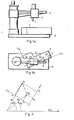
- a radial drilling machine also called boom drilling machine, has a machine body, which (Fig. 1 / a) consists of the base plate 6 and a stand fastened thereon, over which the column is placed with the boom 3, which may be up to 360 ° can be pivoted.
- the drilling carriage 2 with the drilling spindle 1 can be moved on rails along the boom 3.
- the machining position is adjusted on radial drilling machines (FIG. 1 / b) by positioning the drilling spindle 1 by the movement r of the drilling carriage 2 on the boom 5 and by pivoting a of the boom 3, similarly to a polar coordinate system.
- the position and the tolerance of the center points of the holes 5 of the workpiece 4 to be machined are indicated on the work drawing in Cartesian X and Y coordinates.
- Positioning is carried out by marking the individual workpieces or, in the case of larger series, using devices. The first method is quite lengthy and imprecise, the second is extremely expensive and time-consuming.
- the object is achieved to provide a position control of the drilling spindle of a radial drilling machine in such a way that the working positions of the drilling spindle in dependence on the predetermined X, Y coordinates of the drilling centers on the workpiece clamped in the machine regardless of its actual position and actual - Alignment in the machine can be controlled.
- the method according to the invention and the associated circuit arrangement are based on a transformation link between a machine-related polar coordinate system of the radial drilling machine and the workpiece-related Cartesian coordinate system, to which the predetermined X, Y coordinates of the center points of the holes to be formed in the workpiece are known, with knowledge of the relative Position of the two coordinate systems.
- the Cartesian coordinates of the work drawing for the drilling center points and their tolerances the values are transformed from the positioning control into the coordinate system of the radial drilling machine, so that quick and easy positioning is possible.
- coordinates recorded by the radial drilling machine can be transformed into the coordinate system of the workpiece and saved as a program.
- the coordinate systems of the radial drill and the workpiece or the mutual linkage are ig in F. 2 shown.
- the center point P of the drilling spindle moves by adjusting the drilling carriage 2 on the boom 3 along a straight line r, which lies at a distance Kp from the parallel straight line r k intersecting the pivot axis K of the boom 3, and pivots about K along the arc a.
- the polar coordinates of the orthogonal projection P K of the drilling spindle center P on the straight line r k are the radius vector R and the polar angle A.
- the origin 0 of the Cartesian coordinate system of the workpiece 4 is given in the coordinate system of the radial drilling machine with the values R 0 and A 0 , and the position with the angle A x of the axis X.
- the Cartesian coordinates X and Y of the drilling spindle center P in the coordinate system of the workpiece can be calculated from the polar coordinate values R p and A p according to the relationships / 3 /, / 4 /, / 5 / and / 6 /:
- the polar coordinate values R and A p are calculated from the Cartesian coordinates X and Y according to the relationships / 7 /, / 8 /, / 9 / and / 10 / p :
- FIG. 4 The circuit arrangement according to the invention is shown in FIG. 4 and its individual functions are explained by means of FIG. 4.
- the function control and tuning of the individual function groups are determined by the arithmetic and control circuit 10 on the basis of the content of the arithmetic and control program memory circuit 20 and in accordance with the content of the machining program memory circuit 25 by means of the address signals 14, data signals 15 and control signals 16 so that the radial drilling machine can be controlled according to the machining program.
- the arithmetic and control circuit 10 is simultaneously provided with arithmetic tasks for the coordinate transformation.
- the interrupt processing circuit 11 is evaluated by means of the interrupt request signals 17 the enumeration in order of priority and continued for decision in the arithmetic and control circuit 10.
- the clock circuit 12 is used to tune the individual circuit functions by means of the time signals 18, or the interrupt request signals 17 carried by the interrupt evaluation circuit 11 from time to time in the arithmetic and control circuit given.
- the functionality of the individual circuits is carried out by the test and monitoring circuit 13 by means of the test signals 19 and in the event of a fault, the arithmetic and control circuit 10 is reported with the interrupt request signal 17 via the interrupt evaluation circuit 11.
- the arithmetic and control program memory circuit 20 contains the algorithms and data with which the functions and connections of the individual circuits, as well as the connection to the radial drilling machine, the peripherals and the operating personnel are controlled via the arithmetic and control circuit 10 or for transformation tasks converted and executed.
- the circuit 20 is expediently constructed from non-erasable memory chips.
- the machining program storage circuit 25 contains the working data for the radial drilling machine and is determined by the machining program (drilling centers, tolerances, feed and speed values, and corresponding functions, such as loosening - clamping, switching coolant on and off, changing the speed and tool, etc.).
- the circuit is expediently constructed from read-write memory modules with a low current consumption, which keep their contents for a long time.
- the keyboard processing circuit 30 enables keyboard input signals 31 through keyboard 32 for manual input and modification of the machining programs, and generally operator intervention.
- the display processing circuit 35 provides information about the machining program, current drill position and general information for via the display processing signals 36 on the display 37 to supply the operating personnel.
- the travels of the radial drilling machine are measured by the pulse generator 42 and the increments between two queries of the measuring system processing circuit 40 are detected and used to calculate the current position of the drilling spindle point P or the values Rp and Ap continued to the arithmetic and control circuit 10.
- the calculated current position values are checked for correctness with each reference point pass, and in the event of a deviation, an error message is displayed, thereby avoiding rejects.
- the measuring system processing circuit 40 is suitable not only for measuring the coordinates A and R but also for measuring further travel paths, e.g. for the measurement of vertical movements of the drilling spindle or the boom, provided that these are equipped with pulse generators and reference point switches.
- the analog servo output circuit 45 regulates the control of the servo drives for the movement and, according to claim, the controllable main drive for the drilling spindle speed by means of analog servo output signals 46.
- the machine state input circuit 50 processes the machine state input signals 51 from limit switches, pressure switches, sensors, etc. and passes on to the arithmetic and control circuit 10. While the machining program is running, these signals are taken into account when controlling the radial drilling machine.
- the machine state output circuit 55 controls the ver based on the commands of the arithmetic and control circuit 10 via machine state output signals various machine functions (e.g. loosening - clamping, coolant, tool change, feed, level change, etc.) and drives the control panel indicator lamp.
- various machine functions e.g. loosening - clamping, coolant, tool change, feed, level change, etc.
- the machining program input circuit 60 is used to feed the machining program into the machining program storage circuit 25 from a periphery (cassette recorder, punch tape reader, etc.) via the machining program input signals 61 - controlled by the arithmetic and control circuit 10.
- the data is constantly checked for correctness during the entry.
- the machining program output circuit 65 - controlled by the arithmetic and control circuit 10 - outputs the machining program from the program memory circuit 25 through the machining program output signals 66 to a data recorder periphery (cassette recorder, punch tape punch, etc.) or by means of a line printer made a list of the machining program.
- the basic task of the positioning controller which is connected to a radial drilling machine, is to measure the position of the drilling spindle 1 or its center point P and, based on the measurement, to compare the positions of the drilling center points 5 specified in the machining program in the Cartesian coordinate system with the polar coordinate system of the radial drilling machine With the help of a suitable transformation.
- the coordinates R and A of the hole centers are dependent on the programmed parameters R 0 , A O and A of the x, y coordinate system of the template, the bore coordinates X and Y are calculated on the basis of the relationships / 1 /, / 2 /, / 3 /, / 4 /, / 5 /, and / 6 / and saved for later workpiece machining, and in the program
- the corresponding target coordinates R and A with the relationships / 7 /, / 8 /, / 9 /, / 10 /, / 11 / and / 12 / are calculated from the programmed values X and Y.
- the relationship of the two coordinate systems to one another is determined by the parameters R 0 , A O and A x , the associated values R 1 , A 1 and X 11 Y being recorded or output by the control system determining points K 1 and K 2 1 or R 2 , A 2 and X2 , Y2 can be determined with the relationships / 13 /, / 14 /, / 15 /, / 16 / and / 17 / and checked for correctness with the relationships / 18 / and / 19 / can be.
- the machining program is written in the order of work and in Cartesian (workpiece) coordinates and contains the hole centers and tolerances of the holes to be machined (in the case of an expanded configuration, it also contains the drilling depth, feed values, speed values, machine function commands, etc.).
- the entry can be made by teaching, manual entry and from an external data carrier.
- the program itself is independent of the coordinate system of the radial drilling machine and so the workpiece 4 can be clamped onto the base plate 6 in any position.
- the program is saved with test data and thereby enables the detection or improvement of faulty programs.
- the X, Y coordinates of the reference points K 1 , K 2 for determining the parameters R 0 , A 0 , A x always remain the same for all workpieces and templates, they can be permanently programmed in the memory 20, for example.
Landscapes
- Engineering & Computer Science (AREA)
- Human Computer Interaction (AREA)
- Manufacturing & Machinery (AREA)
- Physics & Mathematics (AREA)
- General Physics & Mathematics (AREA)
- Automation & Control Theory (AREA)
- Numerical Control (AREA)
- Drilling And Boring (AREA)
- Automatic Control Of Machine Tools (AREA)
- Perforating, Stamping-Out Or Severing By Means Other Than Cutting (AREA)
Priority Applications (1)
| Application Number | Priority Date | Filing Date | Title |
|---|---|---|---|
| AT82108276T ATE27502T1 (de) | 1981-09-14 | 1982-09-08 | Positionssteuerung der bohrspindel einer radialbohrmaschine. |
Applications Claiming Priority (2)
| Application Number | Priority Date | Filing Date | Title |
|---|---|---|---|
| HU812647A HU185955B (en) | 1981-09-14 | 1981-09-14 | Method and connection arrangement for controlling the positioning for radial drilling machines |
| HU264781 | 1981-09-14 |
Publications (2)
| Publication Number | Publication Date |
|---|---|
| EP0075196A1 true EP0075196A1 (fr) | 1983-03-30 |
| EP0075196B1 EP0075196B1 (fr) | 1987-05-27 |
Family
ID=10960433
Family Applications (1)
| Application Number | Title | Priority Date | Filing Date |
|---|---|---|---|
| EP82108276A Expired EP0075196B1 (fr) | 1981-09-14 | 1982-09-08 | Commande de position de la tige de perçage d'une perceuse radiale |
Country Status (6)
| Country | Link |
|---|---|
| US (1) | US4543635A (fr) |
| EP (1) | EP0075196B1 (fr) |
| AT (1) | ATE27502T1 (fr) |
| CA (1) | CA1186391A (fr) |
| DE (1) | DE3276452D1 (fr) |
| HU (1) | HU185955B (fr) |
Cited By (3)
| Publication number | Priority date | Publication date | Assignee | Title |
|---|---|---|---|---|
| WO1997046925A1 (fr) * | 1996-06-06 | 1997-12-11 | The Boeing Company | Procede permettant d'ameliorer la precision des machines |
| US5949685A (en) * | 1997-06-03 | 1999-09-07 | The Boeing Company | Real-time orientation of machine media to improve machine accuracy |
| US6681145B1 (en) | 1996-06-06 | 2004-01-20 | The Boeing Company | Method for improving the accuracy of machines |
Families Citing this family (5)
| Publication number | Priority date | Publication date | Assignee | Title |
|---|---|---|---|---|
| US4670849A (en) * | 1983-03-31 | 1987-06-02 | Hitachi, Ltd. | Position error correcting method and apparatus for industrial robot |
| JPS61128319A (ja) * | 1984-11-28 | 1986-06-16 | Nippon Kogaku Kk <Nikon> | 駆動装置 |
| ATE125775T1 (de) * | 1988-12-06 | 1995-08-15 | Boral Johns Perry Ind Pty Ltd | Regelsystem für einen motor. |
| SE512338C2 (sv) * | 1998-06-25 | 2000-02-28 | Neos Robotics Ab | System och metod för reglering av en robot |
| JP4450302B2 (ja) * | 2002-03-27 | 2010-04-14 | スター精密株式会社 | 工作機械の数値制御装置 |
Citations (4)
| Publication number | Priority date | Publication date | Assignee | Title |
|---|---|---|---|---|
| US3633011A (en) * | 1968-08-29 | 1972-01-04 | Ibm | Method and apparatus for precisely contouring a workpiece imprecisely positioned on a supporting fixture |
| DE2740507A1 (de) * | 1976-09-08 | 1978-03-16 | Unimation Inc | Verfahren zur programmierung eines programmsteuerbaren manipulators und dementsprechender manipulator |
| GB2022869A (en) * | 1978-05-23 | 1979-12-19 | Mckechnie R E | Method and Apparatus for Programming and Operating a Machine Tool |
| US4208675A (en) * | 1978-03-20 | 1980-06-17 | Agence Nationale De Valorization De La Recherche (Anvar) | Method and apparatus for positioning an object |
Family Cites Families (21)
| Publication number | Priority date | Publication date | Assignee | Title |
|---|---|---|---|---|
| DE1477390B2 (de) * | 1963-05-18 | 1971-05-19 | M Hensoldt & Sohne Optische Werke AG, 6330 Wetzlar | Geraet zur anzeige der verschiebungsgroesse eines schlittens |
| US4370720A (en) * | 1970-12-28 | 1983-01-25 | Hyatt Gilbert P | Coordinate rotation for numerical control system |
| US4120583A (en) * | 1970-12-28 | 1978-10-17 | Hyatt Gilbert P | High registration photomask method and apparatus |
| US4364110A (en) * | 1970-12-28 | 1982-12-14 | Hyatt Gilbert P | Computerized machine control system |
| US3920972A (en) * | 1974-07-16 | 1975-11-18 | Cincinnati Milacron Inc | Method and apparatus for programming a computer operated robot arm |
| US4427970A (en) * | 1974-09-18 | 1984-01-24 | Unimation, Inc. | Encoding apparatus |
| US4002827A (en) * | 1975-05-15 | 1977-01-11 | General Electric Company | Polar coordinate format to a cartesian coordinate format scan converter |
| US3986007A (en) * | 1975-08-20 | 1976-10-12 | The Bendix Corporation | Method and apparatus for calibrating mechanical-visual part manipulating system |
| US4115858A (en) * | 1976-01-12 | 1978-09-19 | Houdaille Industries, Inc. | Machine tool controller employing microprocessor system for controlling Z axis |
| US4043700A (en) * | 1976-11-15 | 1977-08-23 | Toolmatic Corporation | X-Y control for radial arm and headstock of a radial drilling machine |
| US4106021A (en) * | 1977-07-01 | 1978-08-08 | Rca Corporation | Polar to rectangular coordinate converter |
| US4162527A (en) * | 1977-07-29 | 1979-07-24 | Hamill Company, Inc. | Numerically controlled machine tool system with programmable tool offset |
| US4152765A (en) * | 1977-09-15 | 1979-05-01 | Weber John M | Programmer unit for N/C systems |
| JPS5918194B2 (ja) * | 1978-01-31 | 1984-04-25 | ファナック株式会社 | 工業用ロボット制御方法 |
| US4271471A (en) * | 1978-12-28 | 1981-06-02 | Westinghouse Electric Corp. | Method of operating a remotely controlled tool positioning table |
| US4228495A (en) * | 1978-12-19 | 1980-10-14 | Allen-Bradley Company | Multiprocessor numerical control system |
| US4272818A (en) * | 1979-07-19 | 1981-06-09 | The Bendix Corporation | Position feedback control system for a numerically controlled machine tool |
| US4279013A (en) * | 1979-10-31 | 1981-07-14 | The Valeron Corporation | Machine process controller |
| DE3001954A1 (de) * | 1980-01-21 | 1981-08-06 | Vereinigte Glaswerke Gmbh, 5100 Aachen | Verfahren und vorrichtung zur korrektur eines schneidprogramms fuer einen schneidautomaten fuer glasscheiben |
| US4401930A (en) * | 1980-12-30 | 1983-08-30 | Toyota Jidosha Kogyo Kabushiki Kaisha | Method of sensing position of movable body and apparatus therefor |
| US4434437A (en) * | 1981-01-26 | 1984-02-28 | Rca Corporation | Generating angular coordinate of raster scan of polar-coordinate addressed memory |
-
1981
- 1981-09-14 HU HU812647A patent/HU185955B/hu not_active IP Right Cessation
-
1982
- 1982-09-08 EP EP82108276A patent/EP0075196B1/fr not_active Expired
- 1982-09-08 DE DE8282108276T patent/DE3276452D1/de not_active Expired
- 1982-09-08 AT AT82108276T patent/ATE27502T1/de not_active IP Right Cessation
- 1982-09-09 US US06/416,106 patent/US4543635A/en not_active Expired - Fee Related
- 1982-09-13 CA CA000411257A patent/CA1186391A/fr not_active Expired
Patent Citations (4)
| Publication number | Priority date | Publication date | Assignee | Title |
|---|---|---|---|---|
| US3633011A (en) * | 1968-08-29 | 1972-01-04 | Ibm | Method and apparatus for precisely contouring a workpiece imprecisely positioned on a supporting fixture |
| DE2740507A1 (de) * | 1976-09-08 | 1978-03-16 | Unimation Inc | Verfahren zur programmierung eines programmsteuerbaren manipulators und dementsprechender manipulator |
| US4208675A (en) * | 1978-03-20 | 1980-06-17 | Agence Nationale De Valorization De La Recherche (Anvar) | Method and apparatus for positioning an object |
| GB2022869A (en) * | 1978-05-23 | 1979-12-19 | Mckechnie R E | Method and Apparatus for Programming and Operating a Machine Tool |
Cited By (6)
| Publication number | Priority date | Publication date | Assignee | Title |
|---|---|---|---|---|
| WO1997046925A1 (fr) * | 1996-06-06 | 1997-12-11 | The Boeing Company | Procede permettant d'ameliorer la precision des machines |
| US5903459A (en) * | 1996-06-06 | 1999-05-11 | The Boeing Company | Method for product acceptance by improving the accuracy of machines |
| US5920483A (en) * | 1996-06-06 | 1999-07-06 | The Boeing Company | Scaling machine media for thermal effects to improve machine accuracy |
| US6681145B1 (en) | 1996-06-06 | 2004-01-20 | The Boeing Company | Method for improving the accuracy of machines |
| US6980881B2 (en) | 1996-06-06 | 2005-12-27 | The Boeing Company | Software for improving the accuracy of machines |
| US5949685A (en) * | 1997-06-03 | 1999-09-07 | The Boeing Company | Real-time orientation of machine media to improve machine accuracy |
Also Published As
| Publication number | Publication date |
|---|---|
| EP0075196B1 (fr) | 1987-05-27 |
| HU185955B (en) | 1985-04-28 |
| CA1186391A (fr) | 1985-04-30 |
| DE3276452D1 (en) | 1987-07-02 |
| US4543635A (en) | 1985-09-24 |
| ATE27502T1 (de) | 1987-06-15 |
Similar Documents
| Publication | Publication Date | Title |
|---|---|---|
| DE3134315C3 (de) | Verfahren zum Messen der Ist-Position von Werkstückoberflächen und zum Modifizieren von Befehlssignalen | |
| DE102013103137B4 (de) | Normierung der Ausrichtung einer Roboter-Schweißzange | |
| DE2330054C2 (de) | Vorrichtung zur Steuerung der Bewegung eines Arbeitselementes eines Roboterarmes | |
| DE102015107436B4 (de) | Lernfähige Bahnsteuerung | |
| DE4139202C2 (de) | Funkenerosionsmaschine | |
| DE102005027947A1 (de) | Vorrichtung zum Überprüfen einer Störung | |
| DE2141088A1 (de) | Numerisch gesteuerte Werkzeugmaschine | |
| DE1638032B2 (de) | Numerisch arbeitende Programmsteuerung | |
| DE102010063244A1 (de) | Werkzeugmaschine | |
| EP0075196B1 (fr) | Commande de position de la tige de perçage d'une perceuse radiale | |
| DE3408523A1 (de) | Verfahren zur ueberwachung der durch die steuerung der antriebe einer rechnergesteuerten werkzeugmaschine oder eines industrieroboters erzeugten bahn | |
| DE102020132957A1 (de) | Steuervorrichtung, messsystem und messverfahren | |
| DE102004019653B4 (de) | Simulationsvorrichtung | |
| DE3307615C2 (fr) | ||
| DE102007004423A1 (de) | Steuerung eines Betriebes eines Koordinatenmessgerätes | |
| DE102018100490A1 (de) | Steuerung | |
| DE3438007C2 (fr) | ||
| DE102019109258A1 (de) | Wellenformanzeigevorrichtung | |
| DE2941156A1 (de) | Verfahren zum ermiteln der lage einer werkzeugspitze in bezug auf einen werkzeugschlitten einer numerisch gesteuerten werkzeugmaschine, insbesondere drehmaschine | |
| DE102020129885A1 (de) | System und verfahren zum ableiten und anwenden von globalen offsets der numerischen computersteuerung während der messung von teilen auf einem koordinatenmessgerät | |
| DE112020006668T5 (de) | Numerische Steuerungsvorrichtung und numerisches Steuerungsverfahren | |
| DE112016007216B4 (de) | Numerische Steuervorrichtung | |
| DE112021003711T5 (de) | Steuervorrichtung und Steuerverfahren für Werkzeugmaschinen und Steuervorrichtung für eine Slave-Welle | |
| DE112021005180T5 (de) | Numerische Steuervorrichtung und numerisches Steuersystem | |
| DE112021007319T5 (de) | Roboter-Simulationsvorrichtung |
Legal Events
| Date | Code | Title | Description |
|---|---|---|---|
| PUAI | Public reference made under article 153(3) epc to a published international application that has entered the european phase |
Free format text: ORIGINAL CODE: 0009012 |
|
| AK | Designated contracting states |
Designated state(s): AT BE CH DE FR GB IT LI LU NL SE |
|
| ITCL | It: translation for ep claims filed |
Representative=s name: CALVANI SALVI VERONELLI |
|
| EL | Fr: translation of claims filed | ||
| TCNL | Nl: translation of patent claims filed | ||
| 17P | Request for examination filed |
Effective date: 19830930 |
|
| GRAA | (expected) grant |
Free format text: ORIGINAL CODE: 0009210 |
|
| AK | Designated contracting states |
Kind code of ref document: B1 Designated state(s): AT BE CH DE FR GB IT LI LU NL SE |
|
| PG25 | Lapsed in a contracting state [announced via postgrant information from national office to epo] |
Ref country code: NL Effective date: 19870527 Ref country code: IT Free format text: LAPSE BECAUSE OF FAILURE TO SUBMIT A TRANSLATION OF THE DESCRIPTION OR TO PAY THE FEE WITHIN THE PRESCRIBED TIME-LIMIT;WARNING: LAPSES OF ITALIAN PATENTS WITH EFFECTIVE DATE BEFORE 2007 MAY HAVE OCCURRED AT ANY TIME BEFORE 2007. THE CORRECT EFFECTIVE DATE MAY BE DIFFERENT FROM THE ONE RECORDED. Effective date: 19870527 Ref country code: BE Effective date: 19870527 |
|
| REF | Corresponds to: |
Ref document number: 27502 Country of ref document: AT Date of ref document: 19870615 Kind code of ref document: T |
|
| REF | Corresponds to: |
Ref document number: 3276452 Country of ref document: DE Date of ref document: 19870702 |
|
| ET | Fr: translation filed | ||
| PG25 | Lapsed in a contracting state [announced via postgrant information from national office to epo] |
Ref country code: AT Effective date: 19870908 |
|
| PG25 | Lapsed in a contracting state [announced via postgrant information from national office to epo] |
Ref country code: LU Free format text: LAPSE BECAUSE OF NON-PAYMENT OF DUE FEES Effective date: 19870930 Ref country code: LI Effective date: 19870930 Ref country code: CH Effective date: 19870930 |
|
| NLV1 | Nl: lapsed or annulled due to failure to fulfill the requirements of art. 29p and 29m of the patents act | ||
| PLBE | No opposition filed within time limit |
Free format text: ORIGINAL CODE: 0009261 |
|
| STAA | Information on the status of an ep patent application or granted ep patent |
Free format text: STATUS: NO OPPOSITION FILED WITHIN TIME LIMIT |
|
| 26N | No opposition filed | ||
| REG | Reference to a national code |
Ref country code: CH Ref legal event code: PL |
|
| PGFP | Annual fee paid to national office [announced via postgrant information from national office to epo] |
Ref country code: FR Payment date: 19890713 Year of fee payment: 8 |
|
| PGFP | Annual fee paid to national office [announced via postgrant information from national office to epo] |
Ref country code: SE Payment date: 19890921 Year of fee payment: 8 |
|
| PGFP | Annual fee paid to national office [announced via postgrant information from national office to epo] |
Ref country code: GB Payment date: 19890930 Year of fee payment: 8 |
|
| PGFP | Annual fee paid to national office [announced via postgrant information from national office to epo] |
Ref country code: DE Payment date: 19891130 Year of fee payment: 8 |
|
| PG25 | Lapsed in a contracting state [announced via postgrant information from national office to epo] |
Ref country code: GB Effective date: 19900908 |
|
| PG25 | Lapsed in a contracting state [announced via postgrant information from national office to epo] |
Ref country code: SE Effective date: 19900909 |
|
| GBPC | Gb: european patent ceased through non-payment of renewal fee | ||
| PG25 | Lapsed in a contracting state [announced via postgrant information from national office to epo] |
Ref country code: FR Effective date: 19910530 |
|
| PG25 | Lapsed in a contracting state [announced via postgrant information from national office to epo] |
Ref country code: DE Effective date: 19910601 |
|
| REG | Reference to a national code |
Ref country code: FR Ref legal event code: ST |
|
| EUG | Se: european patent has lapsed |
Ref document number: 82108276.5 Effective date: 19910527 |