EP0075313B1 - Dispositif agricole - Google Patents
Dispositif agricole Download PDFInfo
- Publication number
- EP0075313B1 EP0075313B1 EP82108695A EP82108695A EP0075313B1 EP 0075313 B1 EP0075313 B1 EP 0075313B1 EP 82108695 A EP82108695 A EP 82108695A EP 82108695 A EP82108695 A EP 82108695A EP 0075313 B1 EP0075313 B1 EP 0075313B1
- Authority
- EP
- European Patent Office
- Prior art keywords
- agricultural apparatus
- reservoir
- carrier frame
- cultivation material
- microprocessor
- Prior art date
- Legal status (The legal status is an assumption and is not a legal conclusion. Google has not performed a legal analysis and makes no representation as to the accuracy of the status listed.)
- Expired
Links
- 239000000463 material Substances 0.000 claims description 28
- 239000007788 liquid Substances 0.000 claims description 8
- 230000009471 action Effects 0.000 claims description 7
- 235000014676 Phragmites communis Nutrition 0.000 claims description 6
- 230000005484 gravity Effects 0.000 claims description 6
- 238000005259 measurement Methods 0.000 claims description 5
- 238000005192 partition Methods 0.000 claims description 4
- 238000009826 distribution Methods 0.000 claims description 2
- 238000011144 upstream manufacturing Methods 0.000 claims description 2
- 230000003321 amplification Effects 0.000 claims 2
- 238000003199 nucleic acid amplification method Methods 0.000 claims 2
- 230000008878 coupling Effects 0.000 claims 1
- 238000010168 coupling process Methods 0.000 claims 1
- 238000005859 coupling reaction Methods 0.000 claims 1
- 238000003860 storage Methods 0.000 description 68
- 241000721671 Ludwigia Species 0.000 description 17
- 230000001133 acceleration Effects 0.000 description 8
- 230000007246 mechanism Effects 0.000 description 5
- 238000009331 sowing Methods 0.000 description 4
- 238000005507 spraying Methods 0.000 description 4
- 239000000725 suspension Substances 0.000 description 4
- 241000196324 Embryophyta Species 0.000 description 3
- 239000003795 chemical substances by application Substances 0.000 description 3
- 230000000694 effects Effects 0.000 description 3
- 239000003337 fertilizer Substances 0.000 description 3
- 239000012530 fluid Substances 0.000 description 3
- 239000002184 metal Substances 0.000 description 3
- 229910052751 metal Inorganic materials 0.000 description 3
- 238000000034 method Methods 0.000 description 3
- 230000007480 spreading Effects 0.000 description 3
- 238000003892 spreading Methods 0.000 description 3
- 238000012360 testing method Methods 0.000 description 3
- 230000008859 change Effects 0.000 description 2
- 238000013016 damping Methods 0.000 description 2
- 230000001419 dependent effect Effects 0.000 description 2
- 238000010586 diagram Methods 0.000 description 2
- 230000001105 regulatory effect Effects 0.000 description 2
- 230000035939 shock Effects 0.000 description 2
- 241000607479 Yersinia pestis Species 0.000 description 1
- 239000000853 adhesive Substances 0.000 description 1
- 230000001070 adhesive effect Effects 0.000 description 1
- 230000001174 ascending effect Effects 0.000 description 1
- 230000002238 attenuated effect Effects 0.000 description 1
- 230000004888 barrier function Effects 0.000 description 1
- 230000005540 biological transmission Effects 0.000 description 1
- 230000015572 biosynthetic process Effects 0.000 description 1
- 238000006243 chemical reaction Methods 0.000 description 1
- 230000006835 compression Effects 0.000 description 1
- 238000007906 compression Methods 0.000 description 1
- 238000010276 construction Methods 0.000 description 1
- 244000038559 crop plants Species 0.000 description 1
- 230000007423 decrease Effects 0.000 description 1
- 238000013461 design Methods 0.000 description 1
- 238000011161 development Methods 0.000 description 1
- 230000018109 developmental process Effects 0.000 description 1
- 238000006073 displacement reaction Methods 0.000 description 1
- 238000005553 drilling Methods 0.000 description 1
- 238000005429 filling process Methods 0.000 description 1
- 238000005755 formation reaction Methods 0.000 description 1
- 239000011521 glass Substances 0.000 description 1
- 239000008187 granular material Substances 0.000 description 1
- 238000009499 grossing Methods 0.000 description 1
- 238000003306 harvesting Methods 0.000 description 1
- 238000012423 maintenance Methods 0.000 description 1
- 150000002739 metals Chemical class 0.000 description 1
- 239000000575 pesticide Substances 0.000 description 1
- 230000000704 physical effect Effects 0.000 description 1
- 238000012545 processing Methods 0.000 description 1
- 238000004064 recycling Methods 0.000 description 1
- 230000009467 reduction Effects 0.000 description 1
- 239000002689 soil Substances 0.000 description 1
- 239000007787 solid Substances 0.000 description 1
- 239000007921 spray Substances 0.000 description 1
- 230000003068 static effect Effects 0.000 description 1
- 239000000126 substance Substances 0.000 description 1
- 238000005303 weighing Methods 0.000 description 1
- 230000004580 weight loss Effects 0.000 description 1
Images






Classifications
-
- A—HUMAN NECESSITIES
- A01—AGRICULTURE; FORESTRY; ANIMAL HUSBANDRY; HUNTING; TRAPPING; FISHING
- A01C—PLANTING; SOWING; FERTILISING
- A01C7/00—Sowing
- A01C7/08—Broadcast seeders; Seeders depositing seeds in rows
- A01C7/10—Devices for adjusting the seed-box ; Regulation of machines for depositing quantities at intervals
- A01C7/102—Regulating or controlling the seed rate
-
- A—HUMAN NECESSITIES
- A01—AGRICULTURE; FORESTRY; ANIMAL HUSBANDRY; HUNTING; TRAPPING; FISHING
- A01C—PLANTING; SOWING; FERTILISING
- A01C15/00—Fertiliser distributors
- A01C15/005—Undercarriages, tanks, hoppers, stirrers specially adapted for seeders or fertiliser distributors
- A01C15/006—Hoppers
Definitions
- the invention relates to an agricultural device for spreading liquid, powdered or granular cultivated material, with a storage container mounted on a support frame for receiving the cultivated material.
- fertilizers, spraying and spraying agents for weed and pest control machines and devices that are particularly suitable for the respective purpose are used, which carry the material to be spread in a storage container and which are carried out with the help of a tractor, tractor or tractor working agricultural land.
- the cultivation material is driven either by the machine's wheels or by a drive shaft, usually gimbal-mounted, driven by the tractor.
- seeders in which the grain is housed in the seed box carried.
- fertilizer spreaders the powdery to granular material is also carried in a storage container that is filled from above.
- Pesticides and weed control agents are usually carried in liquid form and sprayed or sprayed onto the land or the crop plants via variously operating nozzles.
- the known devices for spreading a certain amount of cultivated material per unit area work mechanically or hydromechanically, in which, depending on the driving speed via metering wheels or throwing vanes for solid substances, or for certain nozzle settings or pressurization for liquids, in advance using tables or should be achieved based on empirical values.
- the preselected settings often lead to incorrect results because the setpoint of the application rate is influenced by unpredictable or undetectable influencing factors. This includes e.g. B.
- the dosing set can only be achieved by constantly checking the amount applied in relation to the area already worked on and continuously adjusting the setting. So far, the volume of the seed box contents has been measured either mechanically by floats which are supposed to rest on the grain surface, optically by sight glasses or electrically by infrared or light barriers or contact switches. All of these methods work insufficiently, because swimmers dig themselves easily into the grain, especially when shaken, contact switches work poorly with light seeds that tend to form bridges, while the other measuring devices quickly become dusty and therefore unusable.
- the object of the invention is therefore to provide the agricultural device of the type mentioned, in which the output of the cultivated material can be metered by detecting the weight of the storage container and thus the weight of the cultivated material carried.
- a cantilever beam is attached to the support frame, on which the storage container is suspended by means of an all-round movable holding member with simultaneous guidance in a vertical direction, and in that a sensor between the storage container and is used to measure the weight of the storage container Support frame is arranged.
- a cantilever beam is fastened to the support frame, on which the storage container is supported from below by means of a holding member with simultaneous guidance in the vertical direction, and a sensor is arranged between the storage container and the supporting frame for detecting the weight of the storage container.
- the storage container is supported outside of the plane of its center of gravity via at least one connecting piece rigidly connecting it to the supporting frame, and at least one strain gauge is arranged on the connecting piece for detecting the weight of the storage container.
- a pneumatic or hydropneumatic spring system is provided between the support frame and the storage container and the spring system as a sensor for detecting the weight of the storage container and in the spring system a pressure sensor serving as a measuring sensor for detecting the weight of the storage container, the spring system having at least two hydropneumatic springs and each Hydropneumatic spring has a piston-cylinder unit and a pressure vessel, which is divided by an elastic partition into a gas pressure section and a hydraulic section, the hydraulic section being connected to the piston-cylinder unit via a line and the gas pressure section being connected to the pressure sensor via a throttle.
- All of the embodiments are based on the common principle of determining the object of the storage container by measuring the weight of the entire container, acceleration forces when starting and braking as well as forces when the device is inclined cannot largely form sources of interference for the measurement.
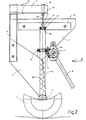
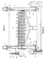
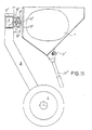
- FIGs 1 and 2 the invention is shown using the example of a sowing or drilling machine, in which the machine frame is supported on an axis 1 and driven with the wheels 2, for example with the aid of a tractor, a tractor or a tractor, over the usable area to be ordered can be.
- a machine frame 3 is attached to the axis 1 on both sides, and a vertical support strut 4 is fastened to this, which supports a horizontal bar in the form of a cantilever or torsion beam 5.
- a vertical support column 6 is also attached, on which the storage container 7, in the example shown the box for receiving the seed grain, is guided.
- the metering wheels 10 sit on the drive shaft 11 and, when the machine is not in use, can be terminated from the supply of seeds by means of the slide 12, which engage in the outlet shafts of the storage container 7.
- the storage container 7 is suspended completely freely, so that there are no fixed, in particular rigid connections to the machine frame 3, 4; it is guided smoothly on both sides in the support columns 6 in the vertical direction and with am Storage tanks attached below ball bearings 13 and above with the help of an approximately in the middle of the storage container 7 attached guide ring 14 which can slide up and down on a pin 15 formed at the upper end of the support column 6.
- the upper end face 14a of the support column 6 serves as a stop for the vertical movement of the storage container 7 in the event of impacts acting on the seeder.
- Both the guide ring 14 and a bolt 17 are fastened to a cross rail 16 which is attached in the upper region to the side faces of the storage container 7.
- a holding tab 18 with a locating bolt 19 is attached above the storage container 7 in the plane of its center of gravity, to which a holding member 20 in the form of an all-round movable support cable is attached, which is anchored at its lower end to the bolt 17 .
- Strain gauges 21 are bonded to the upper and lower surfaces of the two cantilever beams 5, which are connected as resistors in the branches of measuring bridges in such a way that their resistance changes in the deflection of the cantilever beam 5 add up due to the load suspended thereon with respect to the bridge output voltage, because in the Bridge adjacent resistors on opposite surfaces and opposed resistors on the same side of the measuring body.
- the strain gauges 21 therefore have the function of a sensor for the weight of the storage container 7 acting on the holding member 20.
- Damping an RC element then an amplifier with feedback, a balancer for the two measuring bridges and an operational amplifier with an adjusting device for setting the subsequent display instrument to zero when the storage container is empty.
- the display instrument which is expediently arranged in the field of vision of the tractor drive and can be calibrated in kg, kg or liters, shows “zero”.
- the influence of the weight of the drive device for the metering mechanism, which is an integral part of the sowing or spraying machines, on the freely suspended storage container and thus also on the measuring device is expediently avoided by using force transmission means which do not exert any mechanical and weight-distorting forces on the storage container exercise such.
- strain gauges can also be attached to the side surfaces of the cantilever 5 in order to compensate for disturbances, such as strains of the supporting structure due to temperature influences or disturbances due to acceleration forces. So that the suspension cable 20 is tensioned in every operating state, in particular when the container is slightly filled or in the event of impacts, the container 7 is preloaded with the aid of tension springs 22 by a downward force component. In order to prevent damage to the strain gauges in the event of excessive dynamic force and also to prevent their linear resistance range from being exceeded, the vertical movement of the storage container 7 is limited by the stops 14, 14a described in more detail above.
- an elastic spring guide is provided instead of the rigid guidance of the storage container through the support column 6 described above.
- an inclined pair of tension springs 23 are attached to each machine side, which are anchored with their lower ends to horizontal cross members 24 attached to the machine frame, and with their upper ends to the lower side parts of the storage container 7.
- Another tension spring pair 25 running diagonally to the center of the machine is anchored on the one hand to a holder 26 fastened in the middle of the axis 1 and on the other hand also to the two lower outer sides of the storage container 7.
- These pairs of springs 23 and 25 fix the reservoir 7 at its lower region in its desired position, while in the upper region it is held in its working position by the holding members 20 which can move on all sides and which engage in the focal plane.
- the holding members 20 which can move on all sides and which engage in the focal plane.
- the downward preloading of the container 7 is exerted by the tension spring pairs 23 and 25, so that the holding member 20 is always under tension and the seed located in the storage container as a tensile force on the cantilever beams 5 and thus also on the strain gauges 21 as electrical sensors transmits.
- the storage container 7 is suspended on all two cantilever beams 5 with the aid of rubber spring elements 27, which are also known under the name of vibrating metal.
- a tab 28 is attached to the two lateral cross rails 16, with which the rubber spring element 27 is fixedly connected.
- the elastic fixing of the container 7, not shown in this figure, can optionally be carried out in the manner shown in FIG. 4.
- the storage container 7 is supported in its focal plane either in the middle or on its lower outer edges on rubber spring elements 27, which are seated on the cantilever beams 51 laid downwards.
- the yieldingly movable guidance of the storage container is in this embodiment by a Ge provided at the upper end of the support strut 4 Steer 29 causes that together with the rubber spring element 27 allows an up and down movement about the hinge axis 29.
- the rubber spring elements also act as a damping device, so that the vibrations or shocks which may occur during operation do not trigger any undesirable vibrations of the storage container 7.
- Fig. 7 the electrical measuring circuit is shown using a simplified block diagram.
- the strain gauges fastened on the cantilever beam 5 are connected as sensors in the form of variable resistors 21 in a corresponding manner in the branches of a DC measuring bridge 30.
- the strain gauges attached to the top and bottom of the cantilever 5 are arranged in such a way that when the cantilever 5 is loaded they change their resistance values in the sense that they add up their effect in the bridge. So that they do not cancel each other out with regard to their effect in the bridge, adjacent resistances in the bridge when the cantilever beam 5 is loaded must be stressed in the opposite manner and opposite ones in the bridge in the same direction. So you can also all the stretching forces that act like a slide on the top and bottom, such as. B.
- torsion bars can also be used, with a lever arm on which the container hangs or on which it stands.
- the strain gauges must then be glued in spiral lines with a 45 ° slope. strips with opposite signs of action must sit on ascending or descending spiral lines.
- draw beams or compression beams can also be used instead of cantilever beams.
- resistors acting in opposite directions in the bridge must be glued once in the longitudinal direction and once in the transverse direction.
- the dynamic portion of the forces acting on the sensor from the movements of the storage container 7 is greater than the static portion. Therefore, the voltage derived from the measured variable is first filtered or attenuated in an RC element as a low-pass filter 31 and equalized in it as in the subsequent individual amplifier 32.
- the measured values from the two measuring bridges 30 are adapted in the subsequent balancer 33 and fed to an analog or digital indicator 35 via the operational amplifier 34.
- the display of the measuring instrument 35 which can be calibrated, for example, in kg, kg or in liters, can be adjusted with a balancing resistor in such a way that it shows a measurement variable “zero” when the storage container 7 is empty.
- the measuring bridge 30 and the other circuit parts are supplied from the on-board electrical system of the tractor.
- the working voltage of 12 V usually present there is stabilized in a known manner to, for example, 5 V using electrical or electronic switching elements.
- permanent magnets 130 are evenly distributed on the circumference, which generate electrical impulses in the reed switches 200, 300 when the impellers 12 rotate.
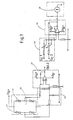
- These impulses and the electrical voltages resulting from the strain gauges 21 are converted into an electrical quantity in a metering control circuit to be described below, with which a direct current control valve 100 is acted upon.
- the energy supply for the hydraulic metering drive comes from the hydraulic pump of the tractor.
- the energy supply runs via the electrically actuated direct current control valve 100 to an oil motor 110 and from there back through the return line 80 to the hydraulic pump of the tractor .
- the oil motor 110 drives the metering drive, which consists, for example, of metering cam wheels 10 arranged on a drive shaft 11 in a known manner.
- the metering wheels 10 can be closed by slides 12 which engage in the discharge pipes 8 of the storage container 7.
- Fig. 8 shows the circuit of the metering control circuit.
- a microprocessor 400 is entered on its input side via the input station 120, the target value of the metered amount of the cultivated material, for example using a keyboard.
- voltage pulses are sent to further inputs of the microprocessor 400 depending on the rotational speed of the impellers.
- the arrangement on both sides allows the different rotational speeds of the impellers to be compensated for when cornering. Via the weighing system 30 already described for FIG.
- the individual amplifier 32, the comparator 33 and the operational amplifier 34 is also present on the microprocessor 400 with a voltage signal analogous to the respective amount of cultivated material in the storage container.
- the reed switches 200 and 300 receive pulses at certain intervals.
- the weight loss for the cultivated agricultural area is given in a simple manner for the given size of the impellers and given machine working width from the number of pulses from the reed switches 200, 300 per interval.
- the quotient thus determined in the microprocessor 400 from the quantity of cultivated material applied and the cultivated agricultural area is compared in the microprocessor 400 with the entered target value.
- Differences in this comparison are converted on the output side of the microprocessor 400 into an electrical signal, which acts in a regulating manner on the direct current control valve 100 and is fed back from there to the input of the microprocessor 400.
- This conversion is stored in an action curve in the microprocessor 400 and is continuously corrected during the application of the cultivated material on the basis of the actually occurring number of impulses - dosage quantity strength - value pairs and approximated to the target value.
- action curves are stored in the microprocessor, which can be selected via the input station 120 at the beginning of the application of the crop according to their suitability for the particular crop to be applied. A test run can also be selected before work on the stand.
- Different current intensities on the DC control valve 100 are determined during certain time intervals by metering the residual amounts in the reservoir after each test time interval, and thus the applied difference in quantity is calculated.
- the test value pairs are saved to improve the impact curve. If there are deviations of a certain amount between the target value and the actual value of the cultivated amount applied during work, a warning display appears.
- the action curve is designed for a specific driving speed, ie for a specific pulse frequency from the reed switches 200 and 300. Frequency deviations are converted by the microprocessor 400 into proportional changes in the operating speed of the metering mechanism.
- the energy supply for the hydraulic metering drive comes from the hydraulic pump of the tractor and runs via the inlet 70 and a flow distributor 90, which stabilizes the fluctuating pressure of the pump at different tractor engine speeds, via the electrically actuated direct current control valve 100 and an oil motor 110 and back through the Backflow 80 into the tractor storage tank.
- the oil motor 110 drives the metering mechanism, which consists of metering wheels 10 on the metering wheel drive shaft 11.
- the power supply for the electrical or electronic control is branched off from the tractor's electrical system.
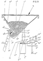
- the reference numeral 7 denotes a seed box accessible from above with a conventional V-shaped cross-sectional shape for receiving the seed 11, which, for. B. is part of a seed drill.
- This seed drill can either be attached to a tractor via a so-called lifting device (not shown) or can have its own chassis.
- a stirrer shaft 12 "for the seed 11" extends in the longitudinal direction through the seed box 7 and is driven by a gear (not shown) at one end of the seed box.
- This gear also drives a shaft 13 "on which 7 seed wheels 16" are fastened at a lateral distance from one another, in each case opposite a seed tube 14 "and an opening 15" in the bottom of the seed box, which have cams on their circumference and the seeds 11 "in feed metered amounts to the seed tubes 14 ".
- the seed wheels 16 “thus form, as it were, locks for the seed 11".
- a number of such seed tubes 14" extend downwards, over which the seed 11 "
- the openings 15 "in the bottom of the seed box 7 can be closed by individual slides 18" which can be actuated via a common operating rod 19 ".
- the slides 18 are slidably mounted in a common clip-shaped holder 20".
- the seed box 7 is supported on supports 21 on two hydropneumatic springs 22 ".
- the supports 21" are by means of piston-shaped extensions 24 "in guide tubes 25" guided vertically.
- the lower end of each support 21 is supported directly on an upwardly projecting extension of the piston 26".
- the pistons 26 ′′ can be biased upwards by the pressure of a hydraulic fluid.
- each of the two cylinders 27 ′′ is connected via a hydraulic line 28 ′′ to a hydraulic section 29 ′′ of a pressure container 30 ′′.
- Another hydraulic line device 31 "connects the hydraulic lines 28" to one another, and this hydraulic line 31 contains a connection, schematically indicated at 32 ", to the hydraulic system of the tractor pulling the drill.
- a pressure container 30" is assigned to each of the two cylinders 27 ", and each pressure vessel 30 "is divided by an elastic partition 33" into the already mentioned hydraulic section 29 "and a gas pressure section 34".
- the gas pressure sections 34 ′′ of the two pressure vessels 30 ′′ are connected to one another by a pipe 50 ′′ having a relatively narrow internal cross section.
- a manometer 52 ′′ is connected to the pipe 50 ′′ via a further pipe 51 ′′.
- a throttle 53 is installed in the pipeline 51" in front of the manometer 52 ".
- the scale of the manometer 52" is calibrated accordingly for measuring the weight of the seed 11 "in the seed box 7.
- the respective weight of the seed box contents can be read continuously during the filling process and subsequently during the work of the seed drill.
- the throttle 53" upstream of the manometer 52 dampens sudden pressure increases and decreases e.g. due to vibrations of the seed drill or due to acceleration or deceleration forces during work.
- the weight of the applied amount of grains can advantageously be continuously checked and the operator can determine relatively easily whether the actual values lie in the target range and the desired high sowing accuracy and thus an optimal plant density can be achieved.
- the seed outflow from the seed box 7 can be regulated, either by appropriate actuation of the slide 18" and / or change in the speed of the shaft 13 "with the seed wheels 16".
Landscapes
- Life Sciences & Earth Sciences (AREA)
- Soil Sciences (AREA)
- Environmental Sciences (AREA)
- Testing Or Calibration Of Command Recording Devices (AREA)
- Catching Or Destruction (AREA)
Claims (32)
Priority Applications (1)
| Application Number | Priority Date | Filing Date | Title |
|---|---|---|---|
| AT82108695T ATE16881T1 (de) | 1981-09-21 | 1982-09-20 | Landwirtschaftliche vorrichtung. |
Applications Claiming Priority (8)
| Application Number | Priority Date | Filing Date | Title |
|---|---|---|---|
| DE3137484 | 1981-09-21 | ||
| DE19813137484 DE3137484A1 (de) | 1981-09-21 | 1981-09-21 | Messvorrichtung an landwirtschaftlichen maschinen und geraeten |
| DE19813137435 DE3137435A1 (de) | 1981-09-21 | 1981-09-21 | Saemaschine, insbesondere drillmaschine zum anhaengen oder anbauen an schlepper oder dgl. |
| DE3137435 | 1981-09-21 | ||
| DE3141104 | 1981-10-16 | ||
| DE19813141104 DE3141104A1 (de) | 1981-10-16 | 1981-10-16 | Vorrichtung an landwirtschaftlichen maschinen und geraeten |
| DE3211683 | 1982-03-30 | ||
| DE19823211683 DE3211683A1 (de) | 1982-03-30 | 1982-03-30 | Messvorrichtung an fahrbaren landwirtschaftlichen maschinen und geraeten |
Publications (2)
| Publication Number | Publication Date |
|---|---|
| EP0075313A1 EP0075313A1 (fr) | 1983-03-30 |
| EP0075313B1 true EP0075313B1 (fr) | 1985-12-11 |
Family
ID=27432705
Family Applications (1)
| Application Number | Title | Priority Date | Filing Date |
|---|---|---|---|
| EP82108695A Expired EP0075313B1 (fr) | 1981-09-21 | 1982-09-20 | Dispositif agricole |
Country Status (2)
| Country | Link |
|---|---|
| EP (1) | EP0075313B1 (fr) |
| DE (1) | DE3267930D1 (fr) |
Cited By (1)
| Publication number | Priority date | Publication date | Assignee | Title |
|---|---|---|---|---|
| WO2012170548A3 (fr) * | 2011-06-10 | 2013-04-11 | Great Plains Manufacturing, Incorporated | Accessoire agricole ayant un système de pesage de trémie |
Families Citing this family (3)
| Publication number | Priority date | Publication date | Assignee | Title |
|---|---|---|---|---|
| DE3774189D1 (de) * | 1986-07-03 | 1991-12-05 | Amazonen Werke Dreyer H | Verteilmaschine. |
| NL8901903A (nl) * | 1989-07-24 | 1991-02-18 | Lely Nv C Van Der | Machine voor het verspreiden van materiaal. |
| CN120883861B (zh) * | 2025-10-09 | 2025-12-12 | 成都市尚品源生态农业有限公司 | 一种羊肚菌大田栽培方法及设备 |
Family Cites Families (3)
| Publication number | Priority date | Publication date | Assignee | Title |
|---|---|---|---|---|
| DE2438575A1 (de) * | 1974-08-10 | 1976-04-29 | Agrocomga Gaede & Co | Drillenkontrolle |
| US4100538A (en) * | 1974-11-20 | 1978-07-11 | Dickey-John Corporation | Seed level sensor for automatic seed planting apparatus |
| FR2432164A1 (fr) * | 1978-07-24 | 1980-02-22 | Lestradet M C J | Dispositif de lecture a distance du niveau d'un liquide dans une capacite, notamment pour les cuves de pulverisateur a usage agricole |
-
1982
- 1982-09-20 EP EP82108695A patent/EP0075313B1/fr not_active Expired
- 1982-09-20 DE DE8282108695T patent/DE3267930D1/de not_active Expired
Cited By (1)
| Publication number | Priority date | Publication date | Assignee | Title |
|---|---|---|---|---|
| WO2012170548A3 (fr) * | 2011-06-10 | 2013-04-11 | Great Plains Manufacturing, Incorporated | Accessoire agricole ayant un système de pesage de trémie |
Also Published As
| Publication number | Publication date |
|---|---|
| DE3267930D1 (en) | 1986-01-23 |
| EP0075313A1 (fr) | 1983-03-30 |
Similar Documents
| Publication | Publication Date | Title |
|---|---|---|
| DE2819365C2 (de) | Streugerät | |
| DE3310424C2 (de) | Vorrichtung zum Ausbringen von Schüttgut, wie Dünger, Saatgut od.dgl. | |
| EP0963690B1 (fr) | Epandeur centrifuge | |
| DE69229986T2 (de) | Streuer | |
| DE102019134184A1 (de) | Landwirtschaftliche Maschine, vorzugsweise zur Bodenbearbeitung und/oder Aussaat und Verfahren zum Steuern und/oder Regeln der Arbeitstiefe einer Werkzeugeinheit | |
| DE3886130T3 (de) | Streuer. | |
| EP2625945B1 (fr) | Procédé de détection de couple des disques d'épandage d'un épandeur à disques et tel épandeur à disques | |
| DE1902715A1 (de) | Landwirtschaftliche Maschine zum Ausstreuen von koernigem Gut,insbesondere von Saat- und/oder Duengemitteln | |
| DE2737099C2 (fr) | ||
| EP0593699A1 (fr) | Balance pour materiau en vrac-----------------------------------. | |
| DE3714642A1 (de) | Landwirtschaftlicher geraeteverbund | |
| DE69725773T2 (de) | Streuer mit Gewichtsmessung | |
| DE3033666C2 (de) | Streugerät, insbesondere Mineraldungstreuer | |
| EP0075313B1 (fr) | Dispositif agricole | |
| DE69519216T2 (de) | Wägevorrichtung | |
| DE3137484A1 (de) | Messvorrichtung an landwirtschaftlichen maschinen und geraeten | |
| DE3137435A1 (de) | Saemaschine, insbesondere drillmaschine zum anhaengen oder anbauen an schlepper oder dgl. | |
| DE102020120409A1 (de) | Verfahren zur Regelung des Streugut-Massenstromes von Scheibenstreuern und Scheibenstreuer zur Durchführung eines solchen Verfahrens | |
| DE3439590C2 (de) | Verteilmaschine zum Ausbringen von insbesondere körnigem Material | |
| DE3141104A1 (de) | Vorrichtung an landwirtschaftlichen maschinen und geraeten | |
| EP0093986B1 (fr) | Appareil agricole mobile | |
| DE3639130C2 (fr) | ||
| DE69710969T2 (de) | Streuer | |
| DE2813670C2 (de) | Fahrbare Maschine zum Ausbringen und Verteilen fließfähiger Stoffe auf oder in den Boden | |
| EP0119292B1 (fr) | Procédé de réglage de l'apport de produits agricoles sur une surface |
Legal Events
| Date | Code | Title | Description |
|---|---|---|---|
| PUAI | Public reference made under article 153(3) epc to a published international application that has entered the european phase |
Free format text: ORIGINAL CODE: 0009012 |
|
| AK | Designated contracting states |
Designated state(s): AT DE FR GB IT NL SE |
|
| 17P | Request for examination filed |
Effective date: 19830324 |
|
| GRAA | (expected) grant |
Free format text: ORIGINAL CODE: 0009210 |
|
| AK | Designated contracting states |
Designated state(s): AT DE FR GB IT NL SE |
|
| PG25 | Lapsed in a contracting state [announced via postgrant information from national office to epo] |
Ref country code: NL Effective date: 19851211 Ref country code: IT Free format text: LAPSE BECAUSE OF FAILURE TO SUBMIT A TRANSLATION OF THE DESCRIPTION OR TO PAY THE FEE WITHIN THE PRESCRIBED TIME-LIMIT;WARNING: LAPSES OF ITALIAN PATENTS WITH EFFECTIVE DATE BEFORE 2007 MAY HAVE OCCURRED AT ANY TIME BEFORE 2007. THE CORRECT EFFECTIVE DATE MAY BE DIFFERENT FROM THE ONE RECORDED. Effective date: 19851211 Ref country code: FR Free format text: THE PATENT HAS BEEN ANNULLED BY A DECISION OF A NATIONAL AUTHORITY Effective date: 19851211 |
|
| REF | Corresponds to: |
Ref document number: 16881 Country of ref document: AT Date of ref document: 19851215 Kind code of ref document: T |
|
| REF | Corresponds to: |
Ref document number: 3267930 Country of ref document: DE Date of ref document: 19860123 |
|
| PG25 | Lapsed in a contracting state [announced via postgrant information from national office to epo] |
Ref country code: SE Effective date: 19860131 |
|
| EN | Fr: translation not filed | ||
| NLV1 | Nl: lapsed or annulled due to failure to fulfill the requirements of art. 29p and 29m of the patents act | ||
| PGFP | Annual fee paid to national office [announced via postgrant information from national office to epo] |
Ref country code: AT Payment date: 19860930 Year of fee payment: 5 |
|
| PLBE | No opposition filed within time limit |
Free format text: ORIGINAL CODE: 0009261 |
|
| STAA | Information on the status of an ep patent application or granted ep patent |
Free format text: STATUS: NO OPPOSITION FILED WITHIN TIME LIMIT |
|
| 26N | No opposition filed | ||
| PG25 | Lapsed in a contracting state [announced via postgrant information from national office to epo] |
Ref country code: GB Effective date: 19890920 Ref country code: AT Effective date: 19890920 |
|
| GBPC | Gb: european patent ceased through non-payment of renewal fee | ||
| PG25 | Lapsed in a contracting state [announced via postgrant information from national office to epo] |
Ref country code: DE Effective date: 19900601 |