EP0075344A1 - Vorrichtung zum Schälen von Oberflächen - Google Patents
Vorrichtung zum Schälen von Oberflächen Download PDFInfo
- Publication number
- EP0075344A1 EP0075344A1 EP82201066A EP82201066A EP0075344A1 EP 0075344 A1 EP0075344 A1 EP 0075344A1 EP 82201066 A EP82201066 A EP 82201066A EP 82201066 A EP82201066 A EP 82201066A EP 0075344 A1 EP0075344 A1 EP 0075344A1
- Authority
- EP
- European Patent Office
- Prior art keywords
- burner
- slab
- carriage
- track
- skid
- Prior art date
- Legal status (The legal status is an assumption and is not a legal conclusion. Google has not performed a legal analysis and makes no representation as to the accuracy of the status listed.)
- Granted
Links
Images



Classifications
-
- B—PERFORMING OPERATIONS; TRANSPORTING
- B23—MACHINE TOOLS; METAL-WORKING NOT OTHERWISE PROVIDED FOR
- B23K—SOLDERING OR UNSOLDERING; WELDING; CLADDING OR PLATING BY SOLDERING OR WELDING; CUTTING BY APPLYING HEAT LOCALLY, e.g. FLAME CUTTING; WORKING BY LASER BEAM
- B23K37/00—Auxiliary devices or processes, not specially adapted for a procedure covered by only one of the other main groups of this subclass
- B23K37/02—Carriages for supporting the welding or cutting element
-
- B—PERFORMING OPERATIONS; TRANSPORTING
- B23—MACHINE TOOLS; METAL-WORKING NOT OTHERWISE PROVIDED FOR
- B23K—SOLDERING OR UNSOLDERING; WELDING; CLADDING OR PLATING BY SOLDERING OR WELDING; CUTTING BY APPLYING HEAT LOCALLY, e.g. FLAME CUTTING; WORKING BY LASER BEAM
- B23K7/00—Cutting, scarfing, or desurfacing by applying flames
- B23K7/08—Cutting, scarfing, or desurfacing by applying flames by applying additional compounds or means favouring the cutting, scarfing or desurfacing procedure
Definitions
- the invention relates to apparatus for scarfing, more particularly for scarfing an inspection track on a flat surface of a steel slab, particularly a slab of ductile steel of deep drawing quality, to enable inspection of the slab.
- the invention also relates to a method of scarfing.
- Scarfing processes are carried out on steel for three distinct reasons.
- the first is to remove flaws such as cracks in a piece of steel, e.g. a slab. This is carried out by means of a hand-held flame torch, which is used to burn away the metal entirely in order to remove the flaw. The operator applies the torch and moves it according to the nature of the flaw being removed.
- scarfing is used to remove a complete surface layer of the steel, particularly with a view to removing any flaws which may be present at the surface.
- One apparatus designed for carrying out this second process is described in GB 847,993, in this case, the entire surface of a steel bar is removed by passing the bar through a scarfing apparatus which provides an annular inwardly directed flame. The bar is moved past the apparatus. Guide means for inserting the bar are provided, and also for guiding the bar after the burned- away surface portion has been removed.
- the third purpose for which scarfing is used is to inspect the quality of a steel slab.
- flaws which may not be visible on the surface of the slab are revealed in the sheet. It is therefore desirable to estimate the number of such sub-surface flaws in the slab, before it is rolled. This may be done, as described in more detail below, by scarfing an inspection track on the slab.
- a criterion for the quality of a slab of steel which is to be rolled is thus the number and type of defects which lie 1 to 3 mm deep under the surface of the slab. These defects, which are formed by inclusions of Al 2 0 3 and Si0 2 and, in the case of continuously cast slab, also by residual casting powder, come to the surface during the further working of the slab due to oxidation of the sheet surface during heating in a furnace and hot-rolling. The oxidized surface layer falls off exposing the steel beneath. They determine the quality of the surface in the finished product. This surface quality is in many cases of great importance, for instance in the case of car bodywork.
- a known method for judging the quality of a slab of rolled steel consists of scarfing an inspection channel on the slab surface using a hand-held blow-torch, the channel having a depth equal to the thickness of the layer which will subsequently be lost by oxidation. The number and type of defects in the inspection channel can then be ascertained.
- inspection channel or track we mean here a channel obtained by scarfing over a width of e.g. about 10 cm for at least a part of the length of the slab parallel to its longitudinal direction.
- a problem in this conventional method of scarfing an inspection track by hand is that accuracy of the estimation of quality is dependent on the competence of the operator in forming an uninterrupted channel of constant depth with a blow-torch.
- the channel tends to be irregular because the operator, when forming the channel, moves continuously along the slab, so that the spacing of the burner of the blow-torch and the slab surface varies.
- the channel depth is therefore not constant.
- the object of the present invention is to provide a scarfing apparatus, which can be simple and cheap, for use in scarfing a regular inspection track, e.g. of uniform depth, in such a way that the quality of a slab of steel can be estimated in a reproducible manner.
- the invention depends on the realisation that, for a satisfactory solution of the problem, the human factor must be removed.
- scarfing machines are known for overall or partial scarfing of steel, but these machines are very expensive and are only usable profitably if there is a high throughput.
- scarfing a channel for inspecting the quality of a slab of steel for rolling one is concerned on the other hand with removing a very small part of the surface of the sheet. It is only necessary for example to form an inspection channel on a very small proportion of the products of a single charge of a continuous casting machine in order to establish the quality of the whole charge.
- Scarfing machines of the conventional type are therefore not profitable for forming tracks for the estimation of the quality of steel slabs, and for extensive technical reasons these machines are not suitable for this purpose.
- a burner carriage carries one or more burners and which slides on at least one skid over the surface of the slab while being guided by a guide track spaced from the slab surface.
- the skid makes substantial contact pressure with the slab surface so that scale is pushed aside or crushed.
- the distance between burner(s) and slab surface can remain as constant as possible, with the advantage that the possibility of obtaining a scarfed track or channel of uniform depth is good. Consequently the quality of a slab of steel can be ascertained with more certainty.
- the apparatus can be of a reliable and simple type, so that it can be cheap and economic at the less intensive usage rate at which it is operated.
- the possibility of obtaining a scarfed track of uniform depth can be improved when the carriage is provided on opposite sides of the location of the track with shields which, together with the slab surface during the scarfing of the track, form a channel, with the burner(s) having an orientation such that oxidised material is blown out of the scarfed track longitudinally along the said channel from the melt pool formed by the burner(s), so that spread of oxidised material over the surface of the slab is prevented by the shields.
- the shields provide the skid surfaces of the carriage.
- this connection is a bellows which can be operated to move the burner carriage away from the slab surface.
- the burner is rotatably mounted on the burner carriage, for rotation in the plane perpendicular to the slab surface and parallel to the inspection track,- so that the burner can be operated in a first position in which the burner forms an initial molten puddle in the slab surface and in a second position in which the burner carriage moves across the slab surface while the burner forms the inspection track.
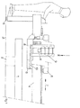
- Fig. 1 shows a horizontal slab 1 of ductile steel of deep drawing quality, supported by support columns 2 standing on the ground 3.
- a guide track 4 forming part of the scarfing apparatus can be moved perpendicularly to the plane of the drawing on schematically shown rails 5.
- a guide carriage 6 runs on the guide track 4 in the direction of the arrow 7.
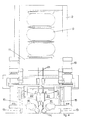
- the guide carriage (see also Fig. 2) is connected to a burner carriage 8 by a pneumatically operated bellows construction 9 and a rod 10.
- the lower end of the bellows 9 rests on a support 11 which is a part of the guide carriage 6 while the burner carriage 8 is suspended from the upper end of the bellows 9.
- a support 11 which is a part of the guide carriage 6 while the burner carriage 8 is suspended from the upper end of the bellows 9.
- the scarfing apparatus is connected to electric cables and hoses for combustible gas, oxygen and compressed air (not shown).
- Figs. 1 and 2 show that the guide track 4 has a portal structure extending over the slab 1, and also provides a stand and controls for the operator.
- Fig. 2 shows only one side of the track 4, for convenience.
- Figs. 3 and 4 show that the burner carriage 8 has a frame 12 which is connected to the guide carriage 6 by the bellows 9 and the rod 10.
- the frame 12 is attached at its underside to two parallel skids 13, through which the burner carriage 8 rests on the slab surface during the process of forming the inspection track.
- the skids extend in the direction of movement of the guide carriage 6 on the guide track 4.
- Fig. 4 shows that the skids 13 are angle forms of unequal flange lengths, with the skid surface formed by the free edge of the longer flanges 12.
- the burner carriage 8 carries two burners 14 whose axes are directed inwardly at an acute angle a to each other (see Fig. 5).
- the burners 14 are so oriented that the plane bisecting the ' angle ⁇ and perpendicular to the slab surface intersects the slab surface along a line which is generally parallel to the direction of movement of the burner carriage 8 across the surface.
- oxidised material is mainly blown out in front of the scarfed channel from the melt'pool formed by the burners due to the momentum communicated by the flame jets.
- flanges 15 which act as shields on either side of the burners.
- These flanges form a channel or gutter 16 with the slab surface.
- the skids 13 also form these shields, but they may alternatively be separate.
- the gutter 16 extends-in front of the burners in the direction of movement of the burners during scarfing.
- The,burners 14 are preferably burners of the type with which it is possible to obtain a smooth scarfed channel, since this leads to high accuracy of estimation of the slab quality.
- each burner 14 is connected to a lever 17 whch is pivotally mounted on the burner carriage by a shaft 18.
- the lever 17 is moved between the two positions by a pneumatic cylinder 19 through a rod 20.
- the burner axis is at a relatively large angle to the slab surface.
- the melt pool is started with a pre-heat flame with the aid of a starter wire 21.
- the burner carriage has for this purpose a clamping device 22 to carry the wire for each burner.
- Each burner can be adjusted to the correct position by means of an adjuster 23 and by rotation and height adjustment of the pneumatic cylinder 19.
- the skids of the burner carriage 8 make contact pressure with the slab equal to at least a part of the weight of the burner carriage, i.e. the frame 12, the bellows 9, the rod 10, the burners 14, the pneumatic cylinders 19, the starter wire devices 22 and other necessary pneumatic accessories and gas supply means, etc. Dirt and scale on the slab surface and any oxidised material which has spread out laterally over the slab surface from the scarfed channel is pushed aside by the skids 13 and/or crushed. In this way, the distance between the burners 14 and the slab surface is kept as constant as possible so that a scarfed inspection channel of uniform depth is obtained.
- skids 13 contact unscarfed regions of the slab surface (in this case regions laterally spaced from the location of the scarfed track, but the skid(s) might alternatively contact the slab surface in front of the region being scarfed). This means that a predetermined thickness of material can be accurately removed.
Landscapes
- Engineering & Computer Science (AREA)
- Mechanical Engineering (AREA)
- Physics & Mathematics (AREA)
- Optics & Photonics (AREA)
- Continuous Casting (AREA)
- Investigating Materials By The Use Of Optical Means Adapted For Particular Applications (AREA)
- Diaphragms For Electromechanical Transducers (AREA)
- Peptides Or Proteins (AREA)
- Chemical And Physical Treatments For Wood And The Like (AREA)
- Waste-Gas Treatment And Other Accessory Devices For Furnaces (AREA)
- Length Measuring Devices With Unspecified Measuring Means (AREA)
- Electrical Discharge Machining, Electrochemical Machining, And Combined Machining (AREA)
- Glass Compositions (AREA)
- Crystals, And After-Treatments Of Crystals (AREA)
Priority Applications (1)
| Application Number | Priority Date | Filing Date | Title |
|---|---|---|---|
| AT82201066T ATE11498T1 (de) | 1981-09-11 | 1982-08-30 | Verfahren und vorrichtung zum schaelen von oberflaechen. |
Applications Claiming Priority (2)
| Application Number | Priority Date | Filing Date | Title |
|---|---|---|---|
| NL8104203A NL8104203A (nl) | 1981-09-11 | 1981-09-11 | Inrichting voor het trekken van een vlamspoor. |
| NL8104203 | 1981-09-11 |
Publications (3)
| Publication Number | Publication Date |
|---|---|
| EP0075344A1 true EP0075344A1 (de) | 1983-03-30 |
| EP0075344B1 EP0075344B1 (de) | 1985-01-30 |
| EP0075344B2 EP0075344B2 (de) | 1988-06-08 |
Family
ID=19838046
Family Applications (1)
| Application Number | Title | Priority Date | Filing Date |
|---|---|---|---|
| EP82201066A Expired EP0075344B2 (de) | 1981-09-11 | 1982-08-30 | Vorrichtung zum Schälen von Oberflächen |
Country Status (8)
| Country | Link |
|---|---|
| US (1) | US4441935A (de) |
| EP (1) | EP0075344B2 (de) |
| JP (1) | JPS5952022B2 (de) |
| AT (1) | ATE11498T1 (de) |
| CA (1) | CA1195216A (de) |
| DE (1) | DE3262153D1 (de) |
| ES (1) | ES515638A0 (de) |
| NL (1) | NL8104203A (de) |
Families Citing this family (3)
| Publication number | Priority date | Publication date | Assignee | Title |
|---|---|---|---|---|
| US7682554B2 (en) * | 2005-08-30 | 2010-03-23 | Kimberly-Clark Worldwide, Inc. | Method and apparatus to mechanically shape a composite structure |
| US7687012B2 (en) * | 2005-08-30 | 2010-03-30 | Kimberly-Clark Worldwide, Inc. | Method and apparatus to shape a composite structure without contact |
| DE202012102639U1 (de) * | 2012-07-17 | 2012-08-06 | Gega Lotz Gmbh | Flämmmaschine zum Flämmen von warmen und kalten Werkstücken, wie Brammen, Blöcke und Knüppel aus Stahl |
Citations (2)
| Publication number | Priority date | Publication date | Assignee | Title |
|---|---|---|---|---|
| GB847993A (en) * | 1958-02-04 | 1960-09-14 | Union Carbide Corp | Improved thermochemical scarfing apparatus |
| FR1590231A (de) * | 1967-10-24 | 1970-04-13 |
Family Cites Families (3)
| Publication number | Priority date | Publication date | Assignee | Title |
|---|---|---|---|---|
| FR1524071A (fr) * | 1966-09-28 | 1968-05-10 | Soudure Autogene Francaise | Dispositif pour le traitement thermique de surfaces de semi-produits métallurgiques |
| AT275272B (de) * | 1967-12-12 | 1969-10-27 | Voest Ag | Flämmeinrichtung für Brammen und Blöcke |
| DE2238460B1 (de) * | 1972-08-04 | 1973-03-22 | Messer Griesheim Gmbh, 6000 Frankfurt | Verfahren zum flaemmen von fehlerstellen |
-
1981
- 1981-09-11 NL NL8104203A patent/NL8104203A/nl not_active Application Discontinuation
-
1982
- 1982-08-30 EP EP82201066A patent/EP0075344B2/de not_active Expired
- 1982-08-30 AT AT82201066T patent/ATE11498T1/de not_active IP Right Cessation
- 1982-08-30 DE DE8282201066T patent/DE3262153D1/de not_active Expired
- 1982-08-31 US US06/413,257 patent/US4441935A/en not_active Expired - Fee Related
- 1982-09-10 ES ES515638A patent/ES515638A0/es active Granted
- 1982-09-10 JP JP57156896A patent/JPS5952022B2/ja not_active Expired
- 1982-09-10 CA CA000411252A patent/CA1195216A/en not_active Expired
Patent Citations (2)
| Publication number | Priority date | Publication date | Assignee | Title |
|---|---|---|---|---|
| GB847993A (en) * | 1958-02-04 | 1960-09-14 | Union Carbide Corp | Improved thermochemical scarfing apparatus |
| FR1590231A (de) * | 1967-10-24 | 1970-04-13 |
Also Published As
| Publication number | Publication date |
|---|---|
| JPS5855173A (ja) | 1983-04-01 |
| JPS5952022B2 (ja) | 1984-12-17 |
| EP0075344B2 (de) | 1988-06-08 |
| ES8306048A1 (es) | 1983-05-01 |
| ES515638A0 (es) | 1983-05-01 |
| EP0075344B1 (de) | 1985-01-30 |
| CA1195216A (en) | 1985-10-15 |
| US4441935A (en) | 1984-04-10 |
| NL8104203A (nl) | 1983-04-05 |
| ATE11498T1 (de) | 1985-02-15 |
| DE3262153D1 (en) | 1985-03-14 |
Similar Documents
| Publication | Publication Date | Title |
|---|---|---|
| JP4632431B2 (ja) | アーク溶接装置 | |
| US4671674A (en) | Process for the detection and recording of weak points or defects on hot iron and steel industry semifinished products | |
| EP0075344B1 (de) | Vorrichtung zum Schälen von Oberflächen | |
| US7378051B2 (en) | Method and apparatus for slitting steel slabs | |
| US4405382A (en) | Scarfing burner arrangement | |
| ATE58228T1 (de) | Verfahren und vorrichtung zum unterhalten der auskleidung eines ofengefaesses. | |
| JP7347403B2 (ja) | 金属板の切断装置及び切断方法、並びに、製品金属板の製造方法 | |
| EP0029070A1 (de) | Vorrichtung für prüfung und behandlung von oberflächen an stahlstücken | |
| JPS645676A (en) | Method and apparatus for welding h-shape steel | |
| CN111590192A (zh) | 一种无缝钢轨的铝热焊方法 | |
| CN211564453U (zh) | 一种板坯角裂清理机 | |
| US4336923A (en) | Steel surface inspection apparatus | |
| JP2022143413A (ja) | 溶接装置及び溶接方法 | |
| US3948433A (en) | Process for the manufacture of a glazing unit | |
| US20070095433A1 (en) | Method and apparatus for treating cracks in slabs | |
| US4103142A (en) | Apparatus and method for use in one-sided welding | |
| KR200269521Y1 (ko) | 연주 슬라브 수동절단 안내장치 | |
| KR100709004B1 (ko) | 슬라브의 토오치 슬래그 제거장치 | |
| SU738796A1 (ru) | Устройство дл кислородной резки проката круглого сечени | |
| GB2096935A (en) | Methods of, and apparatus for, dividing metal slabs or ingots into sections | |
| JPH10193098A (ja) | 金属材料のガス切断方法及び装置 | |
| CA1135174A (en) | Steel surface insepction apparatus | |
| JPH0433560B2 (de) | ||
| JP2839743B2 (ja) | 溶断装置 | |
| JPS5788307A (en) | Method for detecting surface flow of steel billet |
Legal Events
| Date | Code | Title | Description |
|---|---|---|---|
| PUAI | Public reference made under article 153(3) epc to a published international application that has entered the european phase |
Free format text: ORIGINAL CODE: 0009012 |
|
| 17P | Request for examination filed |
Effective date: 19820830 |
|
| AK | Designated contracting states |
Designated state(s): AT BE DE FR GB IT LU NL SE |
|
| ITF | It: translation for a ep patent filed | ||
| GRAA | (expected) grant |
Free format text: ORIGINAL CODE: 0009210 |
|
| AK | Designated contracting states |
Designated state(s): AT BE DE FR GB IT LU NL SE |
|
| REF | Corresponds to: |
Ref document number: 11498 Country of ref document: AT Date of ref document: 19850215 Kind code of ref document: T |
|
| REF | Corresponds to: |
Ref document number: 3262153 Country of ref document: DE Date of ref document: 19850314 |
|
| ET | Fr: translation filed | ||
| NLR4 | Nl: receipt of corrected translation in the netherlands language at the initiative of the proprietor of the patent | ||
| PLBI | Opposition filed |
Free format text: ORIGINAL CODE: 0009260 |
|
| 26 | Opposition filed |
Opponent name: UNION CARBIDE CORPORATION Effective date: 19851030 |
|
| NLR1 | Nl: opposition has been filed with the epo |
Opponent name: UNION CARBIDE CORPORATION |
|
| PUAH | Patent maintained in amended form |
Free format text: ORIGINAL CODE: 0009272 |
|
| STAA | Information on the status of an ep patent application or granted ep patent |
Free format text: STATUS: PATENT MAINTAINED AS AMENDED |
|
| 27A | Patent maintained in amended form |
Effective date: 19880608 |
|
| AK | Designated contracting states |
Kind code of ref document: B2 Designated state(s): AT BE DE FR GB IT LU NL SE |
|
| ITF | It: translation for a ep patent filed | ||
| NLR2 | Nl: decision of opposition | ||
| ET3 | Fr: translation filed ** decision concerning opposition | ||
| NLR3 | Nl: receipt of modified translations in the netherlands language after an opposition procedure | ||
| PGFP | Annual fee paid to national office [announced via postgrant information from national office to epo] |
Ref country code: NL Payment date: 19890831 Year of fee payment: 8 |
|
| PG25 | Lapsed in a contracting state [announced via postgrant information from national office to epo] |
Ref country code: NL Effective date: 19910301 |
|
| NLV4 | Nl: lapsed or anulled due to non-payment of the annual fee | ||
| PGFP | Annual fee paid to national office [announced via postgrant information from national office to epo] |
Ref country code: FR Payment date: 19930713 Year of fee payment: 12 Ref country code: AT Payment date: 19930713 Year of fee payment: 12 |
|
| PGFP | Annual fee paid to national office [announced via postgrant information from national office to epo] |
Ref country code: GB Payment date: 19930715 Year of fee payment: 12 |
|
| PGFP | Annual fee paid to national office [announced via postgrant information from national office to epo] |
Ref country code: BE Payment date: 19930716 Year of fee payment: 12 |
|
| PGFP | Annual fee paid to national office [announced via postgrant information from national office to epo] |
Ref country code: SE Payment date: 19930719 Year of fee payment: 12 |
|
| PGFP | Annual fee paid to national office [announced via postgrant information from national office to epo] |
Ref country code: DE Payment date: 19930721 Year of fee payment: 12 |
|
| PGFP | Annual fee paid to national office [announced via postgrant information from national office to epo] |
Ref country code: LU Payment date: 19930804 Year of fee payment: 12 |
|
| ITTA | It: last paid annual fee | ||
| EPTA | Lu: last paid annual fee | ||
| PG25 | Lapsed in a contracting state [announced via postgrant information from national office to epo] |
Ref country code: LU Free format text: LAPSE BECAUSE OF NON-PAYMENT OF DUE FEES Effective date: 19940830 Ref country code: GB Effective date: 19940830 Ref country code: AT Effective date: 19940830 |
|
| PG25 | Lapsed in a contracting state [announced via postgrant information from national office to epo] |
Ref country code: SE Effective date: 19940831 Ref country code: BE Effective date: 19940831 |
|
| EAL | Se: european patent in force in sweden |
Ref document number: 82201066.6 |
|
| BERE | Be: lapsed |
Owner name: HOOGOVENS GROEP B.V. Effective date: 19940831 |
|
| GBPC | Gb: european patent ceased through non-payment of renewal fee |
Effective date: 19940830 |
|
| PG25 | Lapsed in a contracting state [announced via postgrant information from national office to epo] |
Ref country code: FR Effective date: 19950428 |
|
| PG25 | Lapsed in a contracting state [announced via postgrant information from national office to epo] |
Ref country code: DE Effective date: 19950503 |
|
| EUG | Se: european patent has lapsed |
Ref document number: 82201066.6 |
|
| REG | Reference to a national code |
Ref country code: FR Ref legal event code: ST |