EP0075363A2 - Guidage de coulissement pour panneaux suspendus, verticaux - Google Patents
Guidage de coulissement pour panneaux suspendus, verticaux Download PDFInfo
- Publication number
- EP0075363A2 EP0075363A2 EP82201139A EP82201139A EP0075363A2 EP 0075363 A2 EP0075363 A2 EP 0075363A2 EP 82201139 A EP82201139 A EP 82201139A EP 82201139 A EP82201139 A EP 82201139A EP 0075363 A2 EP0075363 A2 EP 0075363A2
- Authority
- EP
- European Patent Office
- Prior art keywords
- bar
- frame
- panel
- roller guide
- jointing
- Prior art date
- Legal status (The legal status is an assumption and is not a legal conclusion. Google has not performed a legal analysis and makes no representation as to the accuracy of the status listed.)
- Withdrawn
Links
Images
Classifications
-
- E—FIXED CONSTRUCTIONS
- E06—DOORS, WINDOWS, SHUTTERS, OR ROLLER BLINDS IN GENERAL; LADDERS
- E06B—FIXED OR MOVABLE CLOSURES FOR OPENINGS IN BUILDINGS, VEHICLES, FENCES OR LIKE ENCLOSURES IN GENERAL, e.g. DOORS, WINDOWS, BLINDS, GATES
- E06B3/00—Window sashes, door leaves, or like elements for closing wall or like openings; Layout of fixed or moving closures, e.g. windows in wall or like openings; Features of rigidly-mounted outer frames relating to the mounting of wing frames
- E06B3/32—Arrangements of wings characterised by the manner of movement; Arrangements of movable wings in openings; Features of wings or frames relating solely to the manner of movement of the wing
- E06B3/48—Wings connected at their edges, e.g. foldable wings
- E06B3/481—Wings foldable in a zig-zag manner or bi-fold wings
- E06B3/482—Wings foldable in a zig-zag manner or bi-fold wings specially adapted for furniture
-
- E—FIXED CONSTRUCTIONS
- E05—LOCKS; KEYS; WINDOW OR DOOR FITTINGS; SAFES
- E05D—HINGES OR SUSPENSION DEVICES FOR DOORS, WINDOWS OR WINGS
- E05D15/00—Suspension arrangements for wings
- E05D15/26—Suspension arrangements for wings for folding wings
- E05D15/264—Suspension arrangements for wings for folding wings for bi-fold wings
-
- E—FIXED CONSTRUCTIONS
- E05—LOCKS; KEYS; WINDOW OR DOOR FITTINGS; SAFES
- E05Y—INDEXING SCHEME ASSOCIATED WITH SUBCLASSES E05D AND E05F, RELATING TO CONSTRUCTION ELEMENTS, ELECTRIC CONTROL, POWER SUPPLY, POWER SIGNAL OR TRANSMISSION, USER INTERFACES, MOUNTING OR COUPLING, DETAILS, ACCESSORIES, AUXILIARY OPERATIONS NOT OTHERWISE PROVIDED FOR, APPLICATION THEREOF
- E05Y2900/00—Application of doors, windows, wings or fittings thereof
- E05Y2900/20—Application of doors, windows, wings or fittings thereof for furniture, e.g. cabinets
Definitions
- the present invention relates to a roller guide for suspended vertical panels.
- two panels are jointed to each other: one of them, the so-called "fixed” panel, is jointed to the vertical wall of a piece of furniture or of a space along its free vertical edge, whereas the other, the so called moving panel, is jointed along one vertical edge to the fixed panel and along the other vertical edge to a roller guide sliding on a rail placed on the upper of the ceiling or of the space.
- the so-called "fixed” panel is jointed to the vertical wall of a piece of furniture or of a space along its free vertical edge
- the so called moving panel is jointed along one vertical edge to the fixed panel and along the other vertical edge to a roller guide sliding on a rail placed on the upper of the ceiling or of the space.
- rollers which, when panels are in rest position, keep the panels themselves parallel to each other and back inclined as to closing way.
- a drawback of this position is that these rollers don't t allow the complete parallelism of folded panels and the alignment of the outer panel to lateral walls of the space to be closed, and also, as said before, they lower the window of the space.
- the object of the invention is to eliminate the drawbacks jointly and disjointly arising from these well known roller guides and to realize a roller guide which allows panels to be suspended in spaced, parallel relation to each other and to the wall of the space when they are opened, and which allows an easy and correct working in closing and opening operation.
- a roller guide for suspended vertical panels, sliding on a horizontal rail and provided with hinges with meshing gear wheels near the adjacent vertical edges characterized in that it comprises a frame provided with sliding wheels along the rail and a jointing bar placed between the frame and the corresponding panel and moving between two steady extreme symmetric positions, in one position the jointing axis between the bar and the panel being further back, with respect to the closing way, than the jointing axis between the frame and the bar, in the other position said jointing axis being more advanced than the jointing axis between the frame and the bar.
- the roller guide object of the invention, is used in vertical suspended panels, in particular in panels jointed near their vertical adjacent edges thus they have a "working" position, when they are suspended coplanar to each other to realize the doors of a wardrobe or the partition wall of the space, or a "rest” position when, pivoted at 90° and folded as an "accordion", they are suspended in spaced parallel relation to each other.
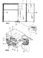
- each pair comprises a first panel 1 jointed, near a vertical edge, to pins 2 connected to the frame of the wardrobe 3, and a second panel 1', jointed to the other vertical edge of the first panel, and near its . opposite vertical edge to a roller guide, generically indicated with 4.
- the joint between the two panels 1,1' is obtained by well-known meshing gear wheels hinges, which assure a high precision and evenness of the jointing movement.
- the number of these hinges 5 is variable and depends on the total height of panels 1,1'.
- roller guide 4 comprises a metallic frame 6 which is provided with wheels 7 with vertical axis and concav outline, engaging themselves with a rail 8 having complementary outline, applied to the upper horizontal edge of the wardrobe.
- the other end of the bar 10 is jointed to the panel 1' near the vertical free edge.
- a solenoidal spring 9 is interposed amidst the bar 10 and the frame 6. This spring is used as a traction one in order to keep elastically the bar 10 in one of the two extreme positions, where it leans against two stops 12,12' provided in the frame 6.
- the stopping position of the two stops 12,12' is such that, near to the two extreme positions of bar 10, the free vertical edge of the panel 1' is adherent to the upper and lower horizontal edges of the wardrobe, and the jointing axis of the bar 10 to the panel I' is symmetrically placed with respect to the vertical orthogonal plane of the front of the wardrobe, said plane passing, through the jointing axis of the bar itself to the metallic frame 6.
- the section In order to obtain the whole camouflage of the box-shaped section when panels 1,1' are coplanar (working position), the section is placed to a level lower than the upper edge of panels, and the jointed engagement between the bar 10 and the panel 1' takes place near a recess 15 obtained in the upper edge of the panel 1'.
- roller guide according to the invention, operates as follows:
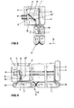
- the sizes of panels 1,1' and of the rail 8 are such that, when the roller is at the end of its running movement, the two panels are not suspended vertically to each other; this position is reached afterward by inertia or thrust owing to the rotation of the bar 10 around its pin 9 jointed to the frame 6.
- the jointing axis to the panel 1' is backward with respect to the jointing axis to the frame 10 when the closing movement begins, on the contrary it is advanced at the end of this movement.
- the spring 11 which keeps elastically the bar 10 in the two extreme positions, also is an effectual shock absorber: in fact casual rough opening and/or closing movements or strokes given to the panels 1,1' during these movements, are partly absorbed from the elastic displacement of the bar 10, and so are notably lightened before reaching the roller guide.
- wardrobes are very high a series of rails and rollers, placed at various lengths, may preferably be used thus making the frame stronger and the opening and closing operations more free.
Landscapes
- Engineering & Computer Science (AREA)
- Civil Engineering (AREA)
- Structural Engineering (AREA)
- Mechanical Engineering (AREA)
- Support Devices For Sliding Doors (AREA)
- Extensible Doors And Revolving Doors (AREA)
Applications Claiming Priority (2)
| Application Number | Priority Date | Filing Date | Title |
|---|---|---|---|
| IT8413381 | 1981-09-18 | ||
| IT84133/81A IT1147497B (it) | 1981-09-18 | 1981-09-18 | Carrello di guida di pannelli verticali sospesi |
Publications (2)
| Publication Number | Publication Date |
|---|---|
| EP0075363A2 true EP0075363A2 (fr) | 1983-03-30 |
| EP0075363A3 EP0075363A3 (fr) | 1984-08-22 |
Family
ID=11324533
Family Applications (1)
| Application Number | Title | Priority Date | Filing Date |
|---|---|---|---|
| EP82201139A Withdrawn EP0075363A3 (fr) | 1981-09-18 | 1982-09-15 | Guidage de coulissement pour panneaux suspendus, verticaux |
Country Status (2)
| Country | Link |
|---|---|
| EP (1) | EP0075363A3 (fr) |
| IT (1) | IT1147497B (fr) |
Cited By (1)
| Publication number | Priority date | Publication date | Assignee | Title |
|---|---|---|---|---|
| IT202200002462A1 (it) * | 2022-02-10 | 2023-08-10 | Salice Arturo Spa | Dispositivo di comando per porte ripiegabili di armadi, cabine armadio o mobili in genere |
Family Cites Families (4)
| Publication number | Priority date | Publication date | Assignee | Title |
|---|---|---|---|---|
| US3022818A (en) * | 1960-06-30 | 1962-02-27 | Int Paper Co | Doorway closure |
| US3344837A (en) * | 1965-07-15 | 1967-10-03 | Hinge Gear Products Inc | Folding panel assembly |
| US3610313A (en) * | 1967-12-19 | 1971-10-05 | Horst Friedrich | Guiding band for folding doors, particularly of furniture bodies |
| DE2039981A1 (de) * | 1970-08-12 | 1972-02-17 | Schmeing Geb | Klapptuerschrank |
-
1981
- 1981-09-18 IT IT84133/81A patent/IT1147497B/it active
-
1982
- 1982-09-15 EP EP82201139A patent/EP0075363A3/fr not_active Withdrawn
Cited By (3)
| Publication number | Priority date | Publication date | Assignee | Title |
|---|---|---|---|---|
| IT202200002462A1 (it) * | 2022-02-10 | 2023-08-10 | Salice Arturo Spa | Dispositivo di comando per porte ripiegabili di armadi, cabine armadio o mobili in genere |
| WO2023151964A1 (fr) * | 2022-02-10 | 2023-08-17 | Arturo Salice S.P.A. | Dispositif d'entraînement pour portes pliables d'armoires, de dressings ou de meubles en général |
| EP4636209A3 (fr) * | 2022-02-10 | 2025-11-05 | Arturo Salice S.p.A. | Dispositif d'entraînement pour portes pliantes de penderie, de placards à pied ou de meubles en général |
Also Published As
| Publication number | Publication date |
|---|---|
| IT8184133A0 (it) | 1981-09-18 |
| EP0075363A3 (fr) | 1984-08-22 |
| IT1147497B (it) | 1986-11-19 |
Similar Documents
| Publication | Publication Date | Title |
|---|---|---|
| EP2167769B1 (fr) | Mécanisme pour la fermeture alignée de portes coulissantes, en particulier pour des unités de meuble ou des compartiments avec deux ou plusieurs portes | |
| EP0119514B1 (fr) | Cloison de séparation | |
| US20120260460A1 (en) | Running gear arrangement having a guide rail for a sliding door | |
| US2895183A (en) | Door construction | |
| EP0706012B1 (fr) | Four de cuisson | |
| US3836223A (en) | Cabinet drawer suspension system | |
| ITMI990631A1 (it) | Meccanismo e complesso per apertura-chiusura di ante complanari adatto a consentire un movimento dell'anta parallelamente a se stessa second | |
| EP0075363A2 (fr) | Guidage de coulissement pour panneaux suspendus, verticaux | |
| DE2831128C2 (fr) | ||
| US11421461B2 (en) | Sliding door soft-closer device | |
| US3222734A (en) | Storm window and screen installation for existing standard window frame structure | |
| US2959827A (en) | Sliding doors and windows | |
| US2644205A (en) | Sliding door structure | |
| EP0193504A2 (fr) | Dispositif permettant le déplacement d'une porte d'armoire ou similaire hors d'un plan dans un second plan parallèle et le coulissement | |
| US2699976A (en) | Extension table with self contained overhanging leaves | |
| KR101947445B1 (ko) | 슬라이드식 3도어를 가지는 장롱의 양방향 댐핑시스템 | |
| DE841634C (de) | Schiebetor, insbesondere fuer grosse OEffnungen | |
| DE102015102139A1 (de) | Caddy-Aufbewahrungsschrank | |
| GB2191528A (en) | Door for display cabinets | |
| US2614296A (en) | Window construction | |
| AU2019229400A1 (en) | Sliding Door Soft-Closer Device | |
| GB2348233A (en) | Shutter door alignment aid | |
| DE345892C (fr) | ||
| DE2817161A1 (de) | Schrankwand | |
| JP6951284B2 (ja) | 建具 |
Legal Events
| Date | Code | Title | Description |
|---|---|---|---|
| PUAI | Public reference made under article 153(3) epc to a published international application that has entered the european phase |
Free format text: ORIGINAL CODE: 0009012 |
|
| AK | Designated contracting states |
Designated state(s): AT BE CH DE FR GB IT LI LU NL SE |
|
| PUAL | Search report despatched |
Free format text: ORIGINAL CODE: 0009013 |
|
| AK | Designated contracting states |
Designated state(s): AT BE CH DE FR GB IT LI LU NL SE |
|
| 17P | Request for examination filed |
Effective date: 19850213 |
|
| 17Q | First examination report despatched |
Effective date: 19861118 |
|
| STAA | Information on the status of an ep patent application or granted ep patent |
Free format text: STATUS: THE APPLICATION IS DEEMED TO BE WITHDRAWN |
|
| 18D | Application deemed to be withdrawn |
Effective date: 19870329 |
|
| RIN1 | Information on inventor provided before grant (corrected) |
Inventor name: BIANCHIN SCARPA, AFRA Inventor name: SCARPA, TOBIA |