EP0075455A2 - Ensemble de bornes d'alimentation de puissance - Google Patents
Ensemble de bornes d'alimentation de puissance Download PDFInfo
- Publication number
- EP0075455A2 EP0075455A2 EP82304905A EP82304905A EP0075455A2 EP 0075455 A2 EP0075455 A2 EP 0075455A2 EP 82304905 A EP82304905 A EP 82304905A EP 82304905 A EP82304905 A EP 82304905A EP 0075455 A2 EP0075455 A2 EP 0075455A2
- Authority
- EP
- European Patent Office
- Prior art keywords
- terminal
- power source
- casing
- substrate
- flange
- Prior art date
- Legal status (The legal status is an assumption and is not a legal conclusion. Google has not performed a legal analysis and makes no representation as to the accuracy of the status listed.)
- Granted
Links
Images


Classifications
-
- H—ELECTRICITY
- H01—ELECTRIC ELEMENTS
- H01R—ELECTRICALLY-CONDUCTIVE CONNECTIONS; STRUCTURAL ASSOCIATIONS OF A PLURALITY OF MUTUALLY-INSULATED ELECTRICAL CONNECTING ELEMENTS; COUPLING DEVICES; CURRENT COLLECTORS
- H01R9/00—Structural associations of a plurality of mutually-insulated electrical connecting elements, e.g. terminal strips or terminal blocks; Terminals or binding posts mounted upon a base or in a case; Bases therefor
- H01R9/16—Fastening of connecting parts to base or case; Insulating connecting parts from base or case
-
- H—ELECTRICITY
- H01—ELECTRIC ELEMENTS
- H01R—ELECTRICALLY-CONDUCTIVE CONNECTIONS; STRUCTURAL ASSOCIATIONS OF A PLURALITY OF MUTUALLY-INSULATED ELECTRICAL CONNECTING ELEMENTS; COUPLING DEVICES; CURRENT COLLECTORS
- H01R4/00—Electrically-conductive connections between two or more conductive members in direct contact, i.e. touching one another; Means for effecting or maintaining such contact; Electrically-conductive connections having two or more spaced connecting locations for conductors and using contact members penetrating insulation
- H01R4/28—Clamped connections, spring connections
- H01R4/30—Clamped connections, spring connections utilising a screw or nut clamping member
-
- H—ELECTRICITY
- H01—ELECTRIC ELEMENTS
- H01R—ELECTRICALLY-CONDUCTIVE CONNECTIONS; STRUCTURAL ASSOCIATIONS OF A PLURALITY OF MUTUALLY-INSULATED ELECTRICAL CONNECTING ELEMENTS; COUPLING DEVICES; CURRENT COLLECTORS
- H01R4/00—Electrically-conductive connections between two or more conductive members in direct contact, i.e. touching one another; Means for effecting or maintaining such contact; Electrically-conductive connections having two or more spaced connecting locations for conductors and using contact members penetrating insulation
- H01R4/58—Electrically-conductive connections between two or more conductive members in direct contact, i.e. touching one another; Means for effecting or maintaining such contact; Electrically-conductive connections having two or more spaced connecting locations for conductors and using contact members penetrating insulation characterised by the form or material of the contacting members
- H01R4/64—Connections between or with conductive parts having primarily a non-electric function, e.g. frame, casing, rail
-
- H—ELECTRICITY
- H01—ELECTRIC ELEMENTS
- H01R—ELECTRICALLY-CONDUCTIVE CONNECTIONS; STRUCTURAL ASSOCIATIONS OF A PLURALITY OF MUTUALLY-INSULATED ELECTRICAL CONNECTING ELEMENTS; COUPLING DEVICES; CURRENT COLLECTORS
- H01R9/00—Structural associations of a plurality of mutually-insulated electrical connecting elements, e.g. terminal strips or terminal blocks; Terminals or binding posts mounted upon a base or in a case; Bases therefor
- H01R9/16—Fastening of connecting parts to base or case; Insulating connecting parts from base or case
- H01R9/18—Fastening by means of screw or nut
-
- H—ELECTRICITY
- H01—ELECTRIC ELEMENTS
- H01R—ELECTRICALLY-CONDUCTIVE CONNECTIONS; STRUCTURAL ASSOCIATIONS OF A PLURALITY OF MUTUALLY-INSULATED ELECTRICAL CONNECTING ELEMENTS; COUPLING DEVICES; CURRENT COLLECTORS
- H01R9/00—Structural associations of a plurality of mutually-insulated electrical connecting elements, e.g. terminal strips or terminal blocks; Terminals or binding posts mounted upon a base or in a case; Bases therefor
- H01R9/22—Bases, e.g. strip, block, panel
- H01R9/28—Terminal boards
Definitions
- the present invention relates to a power source terminal assembly which is packaged in a casing of an electronic instrument for power supply and grounding as well.
- a power source terminal assembly for relaying power source circuits inside and outside of the casing and a grounding terminal.
- FIGs. 1 and 2 are respectively a front view and a plan view, partly in section.
- connectors for relaying crimp-style terminals 1 are constituted by conductor screw rods 3a and 3b, each carrying at opposite end portions thereof pluralities of washers and conductor nuts firmly gripping therebetween the crimp-style terminals 1.
- the screw rod 3a of the grounding terminal is inserted into a hole 5 made in a casing side wall 4 at a predetermined position and clamped by washers and nuts 6 to the side wall 4.
- the screw rods 3b of power source terminals are inserted into holes of a rectangular insulating substrate 7 and fastened thereto by the same method as in the case of the screw rod 3a, forming a power source terminal assembly.
- the substrate 7 of the power source terminal assembly is mounted on the side wall 4 to cover a window made therein in side-by-side relation to the hole 5 and is fastened by tightening its four corners with small screws 9 to the side wall 4.
- An embodiment of the present invention can reduce the large amount of time_for mounting of the terminal screw rods and the substrate.
- An embodiment of the present invention can prevent damage to the casing side wall being caused by an external force applied to the terminal screw rod of the grounding terminal.
- Fig. 3 is a front view showing the assembled state of the power source.terminal assembly of the present invention and Fig. 4 its plan view, partly in section.
- Figs. 3 and 4 the parts corresponding to those in Fig. 1 are identified by the same reference numerals.
- reference numeral lla indicates a terminal screw rod of a grounding terminal; and llb designates terminal screw rods of power source terminals, each of which rods carries at its both end portions washers and nuts 2 for firmly gripping the crimp-style terminalsl.
- the washers and nuts 2 at one end portion of each the terminal screw rods lla and llb are omitted.
- the terminal screw rods lla and llb each have a knurled flange 31 formed as a unitary structure therewith centrally thereof.
- the terminal screw rods lla and llb are molded into an insulation substrate 12 with their flanges 31 partly embedded in the substrate 12.
- a step- shaped recess 13 which extends to one side of the substrate 12, permitting one side of the flange 31 of the terminal screw rod lla to project out on the back of the substrate 12 by the depth t of the recess 13.
- the depth t of the recess 13 is selected so that one side of the flange 31 may abut against the side wall 4 regardless whether the molded substrate 13 has a burr.
- the screw rods of all the terminals including the grounding terminal are molded into a common substrate and the flange of the screw rod of the grounding terminal is disposed at such a position as mentioned above. Accordingly, the power source terminal assembly of the present invention differs in this point from the prior art structure in which the grounding terminal is isolated from the substrate.
- the terminal screw rods lla and llb molded into the substrate 12 are inserted into the hole 5 and window 8 of the side wall 4 and the terminal rod lla is clamped by tightening the nut 6 to the side wall 4 and then the other end portion of the substrate 12 is fastened by a machine screw 9 to the vicinity of the window 8 of the side wall 4.
- the terminal screw rod lla has one side of its flange 31 abutting against the side wall, and hence performs the function of the grounding terminal, but the terminal screw rods llb of the power source terminals stay in the window 8 and, consequently, they are out of contact with the side wall 4.
- the crimp-style terminals connected to wire ends are fastened by the washers and nuts 2 mounted on both sides of each terminal screw rod to perform wiring.
- the power source terminal assembly of the present invention can be mounted by tightening of one nut and one screw, and it is assured that the grounding terminal makes contact with the casing and, in addition, the grounding terminal is molded into the substrate 12. Accordingly, the present invention provides for enhanced efficiency in the mounting operation and improved reliability of wiring and, further, ensures that the grounding terminal is firmly retained to the side wall 4.
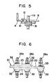
- Fig. 5 shows another means for fixing the substrate 12.
- one end portion of the substrate 12 is retained to the side wall 4 by fastening thereto the terminal rod lla as in the above case, but the other end portion of the substrate 12 is retained to the side wall 4 by engaging the marginal portion of the window 8 of the side wall 4 with a guide groove 41 cut in the edge of the other end portion of the substrate 12.
- F ig. 6 illustrates a modified embodiment/of the present invention.
- a molded insulation substrate 21 is formed by a mounting plate 23 having a recess 22 as in the foregoing embodiment and projections 24 and 25 on both sides thereof, and terminal screw rods 26b of the power source terminal are disposed to extend through the substrate 21 and the projections 24 and 25 formed integrally therewith.
- Both sides of flanges 32 of the terminal screw rods 26b project out of the projections 24 and 25, and crimp-style terminals (not shown ⁇ connected to wire ends are fastened to the end faces of the flanges 32 with nuts inside and outside the casing to perform power source wiring.
- a terminal screw rod 26a of the grounding terminal is disposed to extend through the recessed portion of the mounting plate 23 in the same manner as in the foregoing embodiment.
- Reference numeral 33 indicates a flange of the terminal screw rod 26a.
- this power source terminal block is mounted to the casing by fastening a nut of the terminal screw rod 26a inserted through a hole made in the side wall and engaging the projection 25 with the window of the side wall.
- the present invention produces the following excellent effects:
Landscapes
- Connections Arranged To Contact A Plurality Of Conductors (AREA)
- Connections By Means Of Piercing Elements, Nuts, Or Screws (AREA)
- Coupling Device And Connection With Printed Circuit (AREA)
- Multi-Conductor Connections (AREA)
Applications Claiming Priority (2)
| Application Number | Priority Date | Filing Date | Title |
|---|---|---|---|
| JP148079/81 | 1981-09-18 | ||
| JP56148079A JPS5851479A (ja) | 1981-09-18 | 1981-09-18 | 電源端子板 |
Publications (3)
| Publication Number | Publication Date |
|---|---|
| EP0075455A2 true EP0075455A2 (fr) | 1983-03-30 |
| EP0075455A3 EP0075455A3 (en) | 1983-08-17 |
| EP0075455B1 EP0075455B1 (fr) | 1986-12-03 |
Family
ID=15444748
Family Applications (1)
| Application Number | Title | Priority Date | Filing Date |
|---|---|---|---|
| EP82304905A Expired EP0075455B1 (fr) | 1981-09-18 | 1982-09-17 | Ensemble de bornes d'alimentation de puissance |
Country Status (6)
| Country | Link |
|---|---|
| US (1) | US4486058A (fr) |
| EP (1) | EP0075455B1 (fr) |
| JP (1) | JPS5851479A (fr) |
| AU (1) | AU541481B2 (fr) |
| DE (1) | DE3274603D1 (fr) |
| ES (1) | ES276154Y (fr) |
Cited By (2)
| Publication number | Priority date | Publication date | Assignee | Title |
|---|---|---|---|---|
| EP0895306A1 (fr) * | 1997-07-30 | 1999-02-03 | Sumitomo Wiring Systems, Ltd. | Dispositif de connexion pour un faisceau de câbles pour automobile |
| CN112652912A (zh) * | 2020-12-16 | 2021-04-13 | 迈杰科输配电设备江苏有限公司 | 一种接线端子 |
Families Citing this family (11)
| Publication number | Priority date | Publication date | Assignee | Title |
|---|---|---|---|---|
| JPH047661Y2 (fr) * | 1986-08-20 | 1992-02-27 | ||
| US4764127A (en) * | 1987-05-28 | 1988-08-16 | Edison Price Incorporated | Electrical connector for high-level audio signals |
| JP4030646B2 (ja) * | 1998-02-27 | 2008-01-09 | 花王株式会社 | 脂肪族1級アルコールの酸化方法 |
| JP2000011778A (ja) | 1998-06-22 | 2000-01-14 | Sumitomo Wiring Syst Ltd | ワイヤハーネス用電線の切断寸法設定方法 |
| DE102004045609A1 (de) * | 2004-09-16 | 2006-04-06 | Lowitzki, Jürgen | Anordnung zur Befestigung von Anschlußkabeln |
| FR2877774B1 (fr) * | 2004-11-08 | 2010-11-05 | Airbus France | Ensemble connecteur pour aeronef |
| US7568871B2 (en) * | 2006-01-27 | 2009-08-04 | Panduit Corp. | Data center cabinet bonding stud |
| US8647159B2 (en) * | 2010-03-02 | 2014-02-11 | General Electric Company | Apparatus and method for effecting electrical termination with a plurality of types of termination structures |
| JP5991077B2 (ja) * | 2012-08-27 | 2016-09-14 | ダイキン工業株式会社 | 接続端子の取付構造、ターボ圧縮機及びターボ冷凍機 |
| US10144371B1 (en) * | 2017-09-29 | 2018-12-04 | GM Global Technology Operations LLC | Grounding element including block and plate |
| CN112310702B (zh) * | 2020-11-19 | 2025-08-12 | 上海法雷奥汽车电器系统有限公司 | 一种电源端子 |
Family Cites Families (12)
| Publication number | Priority date | Publication date | Assignee | Title |
|---|---|---|---|---|
| US1768422A (en) * | 1926-11-30 | 1930-06-24 | Pass & Seymour Inc | Electric sign |
| US1741723A (en) * | 1926-12-30 | 1929-12-31 | Pass & Seymour Inc | Sign receptacle |
| US1813716A (en) * | 1930-02-24 | 1931-07-07 | Thordarson Electric Mfg Co | Insulating and supporting washers for electrical binding posts |
| US1984036A (en) * | 1932-10-12 | 1934-12-11 | Western Electric Co | Electrical insulating device having a terminal thereon and a method of making it |
| CH275941A (de) * | 1948-12-23 | 1951-06-15 | Sauter Ag | Klemmenblock, bei der Blockkörper aus Isolierstoff besteht und der zum Einsetzen in Gehäuse elektrischer Apparate bestimmt ist. |
| DE965510C (de) * | 1953-10-20 | 1957-06-13 | Georgii Elektro Motoren Appbau | Halterung fuer durch Bohrungen eines Klemmbrettes durchgesteckte Kontaktverbindungen |
| DE1186123B (de) * | 1960-03-14 | 1965-01-28 | Schoenherr Combinorm Schaltanl | Nulleitertrennklemmleiste |
| US3167608A (en) * | 1961-04-10 | 1965-01-26 | Ansul Chemical Co | Hermetically sealed terminal structure |
| FR1303520A (fr) * | 1961-07-29 | 1962-09-14 | Organe de connexion électrique | |
| US3335387A (en) * | 1965-05-26 | 1967-08-08 | Sperry Rand Corp | Lamp socket |
| US3548360A (en) * | 1966-02-03 | 1970-12-15 | Zenith Radio Corp | Terminal strip |
| US4161622A (en) * | 1976-12-22 | 1979-07-17 | Drayer Sanford A | Insulator assembly having novel feedthrough portion |
-
1981
- 1981-09-18 JP JP56148079A patent/JPS5851479A/ja active Granted
-
1982
- 1982-09-14 US US06/418,009 patent/US4486058A/en not_active Expired - Lifetime
- 1982-09-15 AU AU88414/82A patent/AU541481B2/en not_active Ceased
- 1982-09-17 ES ES1982276154U patent/ES276154Y/es not_active Expired
- 1982-09-17 DE DE8282304905T patent/DE3274603D1/de not_active Expired
- 1982-09-17 EP EP82304905A patent/EP0075455B1/fr not_active Expired
Cited By (4)
| Publication number | Priority date | Publication date | Assignee | Title |
|---|---|---|---|---|
| EP0895306A1 (fr) * | 1997-07-30 | 1999-02-03 | Sumitomo Wiring Systems, Ltd. | Dispositif de connexion pour un faisceau de câbles pour automobile |
| US6036554A (en) * | 1997-07-30 | 2000-03-14 | Sumitomo Wiring Systems, Ltd. | Joint device for an automotive wiring harness |
| CN112652912A (zh) * | 2020-12-16 | 2021-04-13 | 迈杰科输配电设备江苏有限公司 | 一种接线端子 |
| CN112652912B (zh) * | 2020-12-16 | 2022-12-16 | 迈杰科输配电设备江苏有限公司 | 一种接线端子 |
Also Published As
| Publication number | Publication date |
|---|---|
| DE3274603D1 (en) | 1987-01-15 |
| ES276154Y (es) | 1985-03-01 |
| EP0075455A3 (en) | 1983-08-17 |
| AU8841482A (en) | 1983-03-24 |
| JPS5851479A (ja) | 1983-03-26 |
| ES276154U (es) | 1984-08-01 |
| JPS6232582B2 (fr) | 1987-07-15 |
| EP0075455B1 (fr) | 1986-12-03 |
| AU541481B2 (en) | 1985-01-10 |
| US4486058A (en) | 1984-12-04 |
Similar Documents
| Publication | Publication Date | Title |
|---|---|---|
| US3158421A (en) | Electrical connector for a printed circuit board and cable | |
| US6004163A (en) | Electrical multi-pole plug-and-socket-type connector with associated socket part | |
| US4486058A (en) | Power source terminal assembly | |
| US4029377A (en) | Push-on bus bar | |
| US5008493A (en) | Holder with busbars for a busbar system | |
| MY103199A (en) | Slab-like jack module | |
| JP3424150B2 (ja) | 電気コネクタ | |
| US2916721A (en) | Electric control panel | |
| US4580864A (en) | Modular connecting blocks | |
| US3214722A (en) | Terminal assembly for heating panel or the like | |
| US4533195A (en) | Pre-wired modular connecting blocks | |
| US4613192A (en) | Power cord strain relief | |
| JP3285999B2 (ja) | コネクタ用ブスバーホルダ | |
| US5883953A (en) | Telephone and data communications line protection module and grounding spring clip | |
| US4740175A (en) | Electrical receptacle apparatus | |
| JPS5873297A (ja) | 通信ラインのタ−ミナル構造 | |
| JPS5846551Y2 (ja) | プリント配線板用コネクタ | |
| JPS6276167A (ja) | 端子台 | |
| JPH0418190Y2 (fr) | ||
| JPS5873975A (ja) | コネクタ | |
| US3536961A (en) | Wiring device using channel means as a bus bar | |
| JP3055643B2 (ja) | 端子装置 | |
| EP0247006B1 (fr) | Structure de contact en forme de lame pour un appareil électrique | |
| JPH0955269A (ja) | ブスバー回路板 | |
| JP2000201407A (ja) | 分電盤のア―ス中継端子 |
Legal Events
| Date | Code | Title | Description |
|---|---|---|---|
| PUAI | Public reference made under article 153(3) epc to a published international application that has entered the european phase |
Free format text: ORIGINAL CODE: 0009012 |
|
| AK | Designated contracting states |
Designated state(s): DE FR GB |
|
| PUAL | Search report despatched |
Free format text: ORIGINAL CODE: 0009013 |
|
| RHK1 | Main classification (correction) |
Ipc: H01R 9/22 |
|
| AK | Designated contracting states |
Designated state(s): DE FR GB |
|
| 17P | Request for examination filed |
Effective date: 19831021 |
|
| GRAA | (expected) grant |
Free format text: ORIGINAL CODE: 0009210 |
|
| AK | Designated contracting states |
Kind code of ref document: B1 Designated state(s): DE FR GB |
|
| ET | Fr: translation filed | ||
| REF | Corresponds to: |
Ref document number: 3274603 Country of ref document: DE Date of ref document: 19870115 |
|
| PLBE | No opposition filed within time limit |
Free format text: ORIGINAL CODE: 0009261 |
|
| STAA | Information on the status of an ep patent application or granted ep patent |
Free format text: STATUS: NO OPPOSITION FILED WITHIN TIME LIMIT |
|
| 26N | No opposition filed | ||
| PGFP | Annual fee paid to national office [announced via postgrant information from national office to epo] |
Ref country code: GB Payment date: 19920707 Year of fee payment: 11 |
|
| PGFP | Annual fee paid to national office [announced via postgrant information from national office to epo] |
Ref country code: FR Payment date: 19920929 Year of fee payment: 11 |
|
| PGFP | Annual fee paid to national office [announced via postgrant information from national office to epo] |
Ref country code: DE Payment date: 19921125 Year of fee payment: 11 |
|
| PG25 | Lapsed in a contracting state [announced via postgrant information from national office to epo] |
Ref country code: GB Effective date: 19930917 |
|
| GBPC | Gb: european patent ceased through non-payment of renewal fee |
Effective date: 19930917 |
|
| PG25 | Lapsed in a contracting state [announced via postgrant information from national office to epo] |
Ref country code: FR Free format text: LAPSE BECAUSE OF NON-PAYMENT OF DUE FEES Effective date: 19940531 |
|
| PG25 | Lapsed in a contracting state [announced via postgrant information from national office to epo] |
Ref country code: DE Effective date: 19940601 |
|
| REG | Reference to a national code |
Ref country code: FR Ref legal event code: ST |