EP0075488A2 - Convoyeur oscillant - Google Patents
Convoyeur oscillant Download PDFInfo
- Publication number
- EP0075488A2 EP0075488A2 EP82304999A EP82304999A EP0075488A2 EP 0075488 A2 EP0075488 A2 EP 0075488A2 EP 82304999 A EP82304999 A EP 82304999A EP 82304999 A EP82304999 A EP 82304999A EP 0075488 A2 EP0075488 A2 EP 0075488A2
- Authority
- EP
- European Patent Office
- Prior art keywords
- trough
- support structure
- spring plates
- secured
- mounting
- Prior art date
- Legal status (The legal status is an assumption and is not a legal conclusion. Google has not performed a legal analysis and makes no representation as to the accuracy of the status listed.)
- Granted
Links
- 230000005540 biological transmission Effects 0.000 abstract description 5
- 230000001737 promoting effect Effects 0.000 abstract 1
- 238000005303 weighing Methods 0.000 description 31
- 238000005452 bending Methods 0.000 description 5
- 229910000639 Spring steel Inorganic materials 0.000 description 2
- 230000000694 effects Effects 0.000 description 1
- 230000005489 elastic deformation Effects 0.000 description 1
- 230000006698 induction Effects 0.000 description 1
- 238000004806 packaging method and process Methods 0.000 description 1
Images

Classifications
-
- B—PERFORMING OPERATIONS; TRANSPORTING
- B65—CONVEYING; PACKING; STORING; HANDLING THIN OR FILAMENTARY MATERIAL
- B65G—TRANSPORT OR STORAGE DEVICES, e.g. CONVEYORS FOR LOADING OR TIPPING, SHOP CONVEYOR SYSTEMS OR PNEUMATIC TUBE CONVEYORS
- B65G27/00—Jigging conveyors
- B65G27/08—Supports or mountings for load-carriers, e.g. framework, bases, spring arrangements
-
- G—PHYSICS
- G01—MEASURING; TESTING
- G01G—WEIGHING
- G01G13/00—Weighing apparatus with automatic feed or discharge for weighing-out batches of material
- G01G13/02—Means for automatically loading weigh pans or other receptacles, e.g. disposable containers, under control of the weighing mechanism
- G01G13/04—Means for automatically loading weigh pans or other receptacles, e.g. disposable containers, under control of the weighing mechanism involving dribble-feed means controlled by the weighing mechanism to top up the receptacle to the target weight
- G01G13/08—Means for automatically loading weigh pans or other receptacles, e.g. disposable containers, under control of the weighing mechanism involving dribble-feed means controlled by the weighing mechanism to top up the receptacle to the target weight wherein the main feed is effected by mechanical conveying means, e.g. by belt conveyors, by vibratory conveyors
Definitions
- This invention relates to a support structure for a supply trough.
- Supply troughs are used in general for transporting articles and, in the case of a computerized combinatorial weighing apparatus, they are used for transporting articles to be weighed to respective weighing hoppers.
- Such supply trough is so designed and constructed that the trough proper is set into vibration by operation of a vibrator for transporting the articles on the trough proper.
- the supply trough may be resiliently supported on some stationary portion of the combinatorial weighing apparatus by means of coil springs.
- the coil springs may be subjected to a bending stress besides elastic elongation and retraction, the vibrating mode of the coil springs tends to change frequently. Hence, transmission of vibration to the supply trough may not take place as desired, resulting in the articles being transported in an undesirably non- smooth manner on the supply trough.
- An embodiment of the present invention can provide a support structure for resiliently supporting a supply trough on a foundation or other stationary structure, the supply trough being supported on a support base by mounting means and set into vibration by operation of a vibrator for transporting articles on the trough, wherein the support structure consists advantageously of a pair of substantially U-shaped spring plates, one leg of each of the spring plates is secured to front and rear portions on the bottom surface of the mounting base and the other legs of the spring plates are secured to the foundation or stationary structure, whereby the supply trough is supported on the stationary -structure by the medium of the supporting spring plates.
- Such an embodiment can be constructed so that transmission of vibration from the vibrator to the trough may be effected reliably so as to realise a desirably smooth transport of articles on the support trough.
- the design of such a support structure can ensure that it is at least substantially free from undesired lateral bending.
- Figure 1 shows in side elevation a computerized combinatorial weighing apparatus in which embodiments of the present invention can advantageously be incorporated.
- a plurality of weighing hoppers 2 are mounted in a circular array above the circumference of the top opening of a collecting chute 1.
- Each weighing hopper 2 is operatively associated with a weighing machine 3 designed to weigh articles contained in the weighing hopper 2.
- a distribution table 4 is supported on an electromagnetically operated vibrator 5 for supply troughs 6 and is set into helical reciprocating rotation.
- the supply troughs 6 are mounted radially at the outer periphery of the distribution table 4.
- Sensors 8 are used for optically sensing the quantity of the articles received on the distribution table 4.
- a pool hopper 9 is provided between each weighing hopper 2 and the corresponding supply trough 6.
- Each weighing hopper 2 and the corresponding pool hopper 9 are provided with a drive unit 12 and levers 10, 11 adapted for opening and closing the hoppers 2, 9.
- the computerized combination weighing apparatus thus constructed operates as follows.
- the articles are supplied from the distribution table 4 through supply troughs 6 into pool hoppers 9 and thence into weighing hoppers 2.
- the articles thus received in the weighing hoppers 2 are weighed by the weighing machines 3 associated therewith.
- a control unit, not shown, of the computerized combinatorial weighing apparatus Based on the weights measured by the weighing machines, a control unit, not shown, of the computerized combinatorial weighing apparatus performs a combinatorial weighing operation by comparing the result of each combinatorial adding operation performed on the article weights with a preset target weight and selecting the combination of articles, known as the best combination, that gives a total weight equal to the target weight or closest to the target weight.
- the number of articles in the combination may be arbitrary or predetermined, as desired.
- the control unit then operates to open the thus selected weighing hoppers 2 by the operation of the levers 10, 11 so that the articles giving said best combination are released into the collecting chute 1 from the weighing hoppers 2 to be discharged towards a packaging machine or bucket conveyor, not shown. This will leave the selected weighing hoppers 2 empty. Articles are then newly delivered from the corresponding pool hoppers into said weighing hoppers, leaving these pool hoppers empty, whereupon a new supply of articles is delivered from the distribution table 4 and the corresponding supply troughs 6. The weighing operation can be continued in this fashion by repeating the foregoing steps.
- the articles supplied from the distribution table 4 are received in the supply troughs 6 and selected ones of the troughs are vibrated,by the electromagnetically operated vibrators 7 for transporting the articles from the corresponding supply troughs 6 into the corresponding pool hoppers 9.
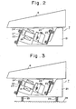
- Figure 2 shows a supply trough assembly
- vibration spring plates 22, 23 are mounted in an inclined attitude to the front and rear parts of a mounting base 21, and a channel-shaped trough 6 is mounted on these spring plates by a mounting metallic fitting 24.
- An intermittently energized induction coil 26 is mounted on the base 21, and a magnetic armature 27 is secured to a bent portion 24' of the fitting 24 so as to be integrated with the spring plate 22 while facing the coil 26.
- the armature 27 is attracted intermittently towards the coil 26 due to elastic deformation of the driving plate springs 22, 23.
- the trough 6 is set into vibration with the left-hand side extremity of the trough, when viewed in Figure 2,being pitched downwardly during vibration owing to the arrangement of the springs 22, 23 and fitting 24.
- the articles placed on the trough 6 may be transported forwardly or from right to left in Figure 2.
- the trough is supported resiliently on a stationary portion of the weighing apparatus by means of resilient elements in the hope that the vibration of the spring plates 22, 23 will be transmitted to the trough smoothly while no transmission of vibration to members other than the troughs will normally occur.
- Figure 3 shows such support means for the conventional supply trough, wherein like numerals are used to designate the same parts shown in Figure 2.
- coil springs 29, 29 of a comparatively large spring constant are used for resiliently supporting the mounting base 21 of the supply trough on a stationary portion 28 of the combinatorial-weighing apparatus.
- the trough 6 is supported resiliently by coil springs 29, 29 on the stationary portion 28, since the coil springs . 29, 29 may be subjected to a bending stress besides elastic elongation and retraction, there may be frequent changes in the vibratory mode of the coil springs, thereby affecting the transmission of the vibratory force to the trough. The result is that the articles may not be transported along the trough 6 in a sufficiently smooth fashion.
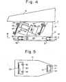
- Figure 4 shows supply trough apparatus embodying the present invention, in side elevation, and Figure 5 shows part of that apparatus in underneath plan view corresponding to section line IV-IV in Figure 4.
- the numerals 30, 31 designate U-shaped support springs having a spring constant substantially equal to that of the aforementioned coil springs 29.
- the numerals 32, 33, 34, 35 - designate bolts for securing the spring plates 30, 31 to the mounting base 21 and the stationary portion of the apparatus.
- the supporting spring plates 30, 31 are formed by bending spring steel plates into a U-shaped configuration.
- the spring constants of the support plate springs 30, 31 are selected to be approximately equal to those of the coil springs 29 mentioned above.
- First legs 30', 31' of the respective U-shaped springs 30, 31 are respectively secured by bolts 32, 33 to the base 21, while the other legs 30", 31" of the U-shaped springs are respectively secured by bolts 34, 35 to the stationary part 28 of the weighing apparatus.
- the bolts 32 through 35 may be replaced by nuts and stud bolts inserted into the base 21 and the stationary part 28 of the weighing apparatus.
- the supporting spring plates 30, 31, used as resilient members or elements for resiliently supporting the supply trough on the stationary part 28, are formed of U-shaped spring steel plates (leaf-springs). Hence, some lateral bending effects that areencountered with the coil springs 29 may be avoided and the vibratory force of the vibration spring plates 22, 23 may be transmitted desirably smoothly to the trough 6, so that the articles can be transported more continuously and uniformly on the supply trough 6.
- the supply trough is supported by vibration spring plates mounted in the inclined position on the mounting base, and may be set into vibration by operation of a vibrator, whereby the articles may be transported on the supply trough.
- the trough is supported on some stationary portion of the automatic combination weighing apparatus or the like by the medium of resilient elements in the form of substantially U-shaped support spring plates. Respective first legs of these U-shaped spring plates are secured to forward and rearward portions of the bottom surface of the supply trough base, and the other legs of the spring plates are secured to the stationary part of the automatic combination weighing apparatus or the like.
- the supply trough thus supported on the support structure can operate in a near optimum vibrating condition.
Landscapes
- Physics & Mathematics (AREA)
- General Physics & Mathematics (AREA)
- Engineering & Computer Science (AREA)
- Mechanical Engineering (AREA)
- Jigging Conveyors (AREA)
- Weight Measurement For Supplying Or Discharging Of Specified Amounts Of Material (AREA)
Applications Claiming Priority (2)
| Application Number | Priority Date | Filing Date | Title |
|---|---|---|---|
| JP14076781U JPS5847138U (ja) | 1981-09-22 | 1981-09-22 | 供給トラフの支持構造 |
| JP140767/81 | 1981-09-22 |
Publications (3)
| Publication Number | Publication Date |
|---|---|
| EP0075488A2 true EP0075488A2 (fr) | 1983-03-30 |
| EP0075488A3 EP0075488A3 (en) | 1983-08-24 |
| EP0075488B1 EP0075488B1 (fr) | 1986-07-30 |
Family
ID=15276268
Family Applications (1)
| Application Number | Title | Priority Date | Filing Date |
|---|---|---|---|
| EP19820304999 Expired EP0075488B1 (fr) | 1981-09-22 | 1982-09-22 | Convoyeur oscillant |
Country Status (4)
| Country | Link |
|---|---|
| EP (1) | EP0075488B1 (fr) |
| JP (1) | JPS5847138U (fr) |
| AU (1) | AU544008B2 (fr) |
| DE (1) | DE3272333D1 (fr) |
Cited By (2)
| Publication number | Priority date | Publication date | Assignee | Title |
|---|---|---|---|---|
| DE4008905A1 (de) * | 1990-03-20 | 1991-09-26 | Cyrus Gmbh Schwingtechnik | Schwingfoerderer |
| WO2003087736A1 (fr) | 2002-04-07 | 2003-10-23 | Bilwinco A/S | Machine de pesage |
Families Citing this family (2)
| Publication number | Priority date | Publication date | Assignee | Title |
|---|---|---|---|---|
| CN107323968A (zh) * | 2017-08-12 | 2017-11-07 | 福建德丰智能装备有限公司 | 45°送料结构 |
| DE102024115769B4 (de) * | 2024-06-06 | 2026-05-13 | Qlar Europe Gmbh | Vibrationsfördereinrichtung mit einer Förderrinne sowie Dosiereinrichtung mit einer Vibrationsfördereinrichtung |
Family Cites Families (5)
| Publication number | Priority date | Publication date | Assignee | Title |
|---|---|---|---|---|
| DE625492C (de) * | 1936-02-10 | Alois Gattner | Auf Schwingfedern abtestuetzte Sieb- oder Foerderrutsche | |
| DE591471C (de) * | 1931-12-20 | 1934-01-22 | Fried Krupp Grusonwerk Akt Ges | Kreis- oder Ellipsenschwingungen ausfuehrende mechanische Vorrichtung |
| GB776699A (en) * | 1955-05-27 | 1957-06-12 | Pneumatic Scale Corp | Material feeding device |
| US3087603A (en) * | 1961-07-11 | 1963-04-30 | Sperry Rand Corp | Vibratory feeder |
| DE2646988A1 (de) * | 1976-10-18 | 1978-04-20 | Technical Development Corp | Einrichtung zum abwaegen von tabakportionen (ii) |
-
1981
- 1981-09-22 JP JP14076781U patent/JPS5847138U/ja active Pending
-
1982
- 1982-09-16 AU AU88443/82A patent/AU544008B2/en not_active Ceased
- 1982-09-22 EP EP19820304999 patent/EP0075488B1/fr not_active Expired
- 1982-09-22 DE DE8282304999T patent/DE3272333D1/de not_active Expired
Cited By (3)
| Publication number | Priority date | Publication date | Assignee | Title |
|---|---|---|---|---|
| DE4008905A1 (de) * | 1990-03-20 | 1991-09-26 | Cyrus Gmbh Schwingtechnik | Schwingfoerderer |
| WO2003087736A1 (fr) | 2002-04-07 | 2003-10-23 | Bilwinco A/S | Machine de pesage |
| US7071425B2 (en) | 2002-04-07 | 2006-07-04 | Bilwinco A/S | Weighing machine having a central distributor to scales |
Also Published As
| Publication number | Publication date |
|---|---|
| JPS5847138U (ja) | 1983-03-30 |
| AU8844382A (en) | 1983-03-31 |
| EP0075488B1 (fr) | 1986-07-30 |
| DE3272333D1 (en) | 1986-09-04 |
| AU544008B2 (en) | 1985-05-16 |
| EP0075488A3 (en) | 1983-08-24 |
Similar Documents
| Publication | Publication Date | Title |
|---|---|---|
| EP0109844B1 (fr) | Peser d'un lot d'articles melangés | |
| EP0074260A2 (fr) | Dispositif de pesage combinatoire | |
| EP0464944B1 (fr) | Dispositif pour remplir des récipients avec des produits tels que des fruits | |
| US6376784B1 (en) | Vibrating transport apparatus and method of detecting vibration characteristic | |
| US4515231A (en) | Combinatorial weighing apparatus with serial weighing operations | |
| US4564103A (en) | Method and apparatus for conveying linear articles | |
| EP0075488B1 (fr) | Convoyeur oscillant | |
| GB2153092A (en) | Dispersion feeder | |
| EP0074826B1 (fr) | Table de distribution pour régler la vitesse d'alimentation d'articles | |
| GB2136974A (en) | Feeding device for combination weighing machine | |
| CN214113918U (zh) | 一种高精度微型微电脑组合秤 | |
| EP0076113B1 (fr) | Dispositif de pesage avec une série de machines de pesage | |
| US5258581A (en) | Product feeding mechanism for a combination machine | |
| JP5590977B2 (ja) | 直進フィーダ及びそれを用いた組合せ秤 | |
| EP1847817A2 (fr) | Appareil de pesée par combinaison | |
| US3703233A (en) | Vibratory feeding apparatus | |
| US6464070B1 (en) | Linear conveyor and method for controlling the same | |
| EP0076114B1 (fr) | Transporteurs à vibrations | |
| JP2579347Y2 (ja) | 組合せ秤の物品供給装置 | |
| US2804992A (en) | Bowl feeding gravimetric feeder | |
| US3228517A (en) | Apparatus for conveying powdery material | |
| US3334787A (en) | Vibratory hopper feeder | |
| US4565279A (en) | Product accumulating conveyor apparatus and method | |
| US3020966A (en) | Automatic weighing machine | |
| JP4528407B2 (ja) | リニア搬送装置およびその制御方法 |
Legal Events
| Date | Code | Title | Description |
|---|---|---|---|
| PUAI | Public reference made under article 153(3) epc to a published international application that has entered the european phase |
Free format text: ORIGINAL CODE: 0009012 |
|
| AK | Designated contracting states |
Designated state(s): DE FR GB IT |
|
| PUAL | Search report despatched |
Free format text: ORIGINAL CODE: 0009013 |
|
| AK | Designated contracting states |
Designated state(s): DE FR GB IT |
|
| 17P | Request for examination filed |
Effective date: 19840215 |
|
| GRAA | (expected) grant |
Free format text: ORIGINAL CODE: 0009210 |
|
| STAA | Information on the status of an ep patent application or granted ep patent |
Free format text: STATUS: THE PATENT HAS BEEN GRANTED |
|
| AK | Designated contracting states |
Kind code of ref document: B1 Designated state(s): DE FR GB IT |
|
| ITF | It: translation for a ep patent filed | ||
| REF | Corresponds to: |
Ref document number: 3272333 Country of ref document: DE Date of ref document: 19860904 |
|
| ET | Fr: translation filed | ||
| PLBI | Opposition filed |
Free format text: ORIGINAL CODE: 0009260 |
|
| 26 | Opposition filed |
Opponent name: CYRUS GMBH SCHWINGTECHNIK Effective date: 19861125 |
|
| PLBG | Opposition deemed not to have been filed |
Free format text: ORIGINAL CODE: 0009274 |
|
| 26D | Opposition deemed not to have been filed |
Opponent name: CYRUS GMBH SCHWINGTECHNIK Effective date: 19870815 |
|
| ITTA | It: last paid annual fee | ||
| PGFP | Annual fee paid to national office [announced via postgrant information from national office to epo] |
Ref country code: FR Payment date: 19950911 Year of fee payment: 14 |
|
| PGFP | Annual fee paid to national office [announced via postgrant information from national office to epo] |
Ref country code: GB Payment date: 19950913 Year of fee payment: 14 |
|
| PGFP | Annual fee paid to national office [announced via postgrant information from national office to epo] |
Ref country code: DE Payment date: 19950928 Year of fee payment: 14 |
|
| PG25 | Lapsed in a contracting state [announced via postgrant information from national office to epo] |
Ref country code: GB Effective date: 19960922 |
|
| PG25 | Lapsed in a contracting state [announced via postgrant information from national office to epo] |
Ref country code: FR Effective date: 19960930 |
|
| GBPC | Gb: european patent ceased through non-payment of renewal fee |
Effective date: 19960922 |
|
| PG25 | Lapsed in a contracting state [announced via postgrant information from national office to epo] |
Ref country code: DE Effective date: 19970603 |
|
| REG | Reference to a national code |
Ref country code: FR Ref legal event code: ST |
|
| REG | Reference to a national code |
Ref country code: FR Ref legal event code: ST |
|
| RIN2 | Information on inventor provided after grant (corrected) |
Inventor name: KITAGAWA, KAZUMI |