EP0075498A1 - Hohlraumresonatorfilter mit Verkopplung nicht benachbarter Resonatoren - Google Patents
Hohlraumresonatorfilter mit Verkopplung nicht benachbarter Resonatoren Download PDFInfo
- Publication number
- EP0075498A1 EP0075498A1 EP82401575A EP82401575A EP0075498A1 EP 0075498 A1 EP0075498 A1 EP 0075498A1 EP 82401575 A EP82401575 A EP 82401575A EP 82401575 A EP82401575 A EP 82401575A EP 0075498 A1 EP0075498 A1 EP 0075498A1
- Authority
- EP
- European Patent Office
- Prior art keywords
- slot
- cavities
- guide
- coupling
- filter
- Prior art date
- Legal status (The legal status is an assumption and is not a legal conclusion. Google has not performed a legal analysis and makes no representation as to the accuracy of the status listed.)
- Granted
Links
- 238000010168 coupling process Methods 0.000 title claims abstract description 37
- 238000005859 coupling reaction Methods 0.000 title claims abstract description 37
- 230000008878 coupling Effects 0.000 title claims abstract description 36
- 239000002184 metal Substances 0.000 claims description 3
- 230000000149 penetrating effect Effects 0.000 claims 1
- 210000000554 iris Anatomy 0.000 description 14
- 230000003313 weakening effect Effects 0.000 description 3
- 230000015572 biosynthetic process Effects 0.000 description 2
- 238000007796 conventional method Methods 0.000 description 2
- 230000007423 decrease Effects 0.000 description 2
- 238000003786 synthesis reaction Methods 0.000 description 2
- 238000013459 approach Methods 0.000 description 1
- 239000006185 dispersion Substances 0.000 description 1
- 230000000694 effects Effects 0.000 description 1
- 230000005684 electric field Effects 0.000 description 1
- 238000005516 engineering process Methods 0.000 description 1
- 238000003780 insertion Methods 0.000 description 1
- 230000037431 insertion Effects 0.000 description 1
- 238000004519 manufacturing process Methods 0.000 description 1
- 238000005259 measurement Methods 0.000 description 1
- 238000000034 method Methods 0.000 description 1
- 238000012552 review Methods 0.000 description 1
- 238000012546 transfer Methods 0.000 description 1
Images
Classifications
-
- H—ELECTRICITY
- H01—ELECTRIC ELEMENTS
- H01P—WAVEGUIDES; RESONATORS, LINES, OR OTHER DEVICES OF THE WAVEGUIDE TYPE
- H01P1/00—Auxiliary devices
- H01P1/20—Frequency-selective devices, e.g. filters
- H01P1/207—Hollow waveguide filters
- H01P1/208—Cascaded cavities; Cascaded resonators inside a hollow waveguide structure
Definitions
- the present invention relates to band pass type cavity filters.
- these filters are obtained by a series mounting of resonant cavities each tuned by a movable plunger (screw), the adjacent cavities being coupled together by irises or by rod curtains.
- the coupling coefficient existing between two adjacent cavities is defined by the opening of the iris or the spacing between the rod curtains according to the technology used and can be adjusted by means of a coupling screw which modifies the susceptance presented by the iris or the curtain of stems.
- Such filters have a symmetrical amplitude / frequency response, of the Chebyshev type or of the Butterworth type.
- the object of the present invention is to avoid the aforementioned drawbacks.
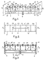
- the filter shown in FIG. 1 is a filter of the bandpass type, produced in a waveguide of rectangular section, 1.
- the incident signal enters through an access E located at one end 3 of the guide and exits through an access S located at the other end 4 of the guide.
- the filter comprises a set of 6 cavities CI to C6 arranged in series in the waveguide which is straight.
- These cavities which are mounted in series, are electrically coupled by means of the irises 12 to 16. These irises are all aligned and their dimensions are determined so that they each have a given susceptibility to the incoming electromagnetic wave. . This susceptance defines the value of the coupling coefficient between each cavity.
- Screws ql to q7, emerging from the waveguide, are respectively screwed through the coupling plates Vl to V7 to open into the irises II to 17; by driving them into the irises, the screws make it possible to adjust the coupling coefficient by slightly modifying the susceptance of the irises.
- a slot, L In this lower face 2, represented in FIG. 2, is cut a slot, L, the length of which is determined by the distance which separates the cavities to be coupled in order to obtain a pseudo-elliptical response.
- This slot L which goes from the cavity C2 to the cavity C5 is arranged parallel to the longitudinal edges of the guide and its ends are located respectively at the middle of the cavities C2 and C5 in order to maintain the symmetry of the response and to obtain a good performance, because the slot L behaves like a slot line or an antenna and allows part of the energy to pass directly from the cavity C2 to the cavity C5.
- the ends of the slot have an enlarged part in the shape of T, E and E ', so as to amplify this phenomenon. Indeed, the widened slot ends make it possible to strongly couple the cavities C2 and C5 while there is practically no transfer of energy between the cavities C3 and C4 and the slot L due to the small width of the slot where it cuts the bottom of these cavities.
- This embodiment is improved by adding two small antennas A, A ', which radiate respectively inside the cavities C2 and C5.
- Each antenna is constituted by a conducting wire, one of the ends of which is electrically connected to one end of the slot; A is connected to E and A 'is connected to E'.
- the housing 5 of parallelepiped shape, shown in section in FIG. 3, is integral with the guide by its ends 8 and 9 which are welded respectively to the ends 3 and 4 of the guide.
- the wall of the housing 5 opposite the slot L is crossed by a screw, 6, accessible from the outside of the filter to allow frequency adjustment.
- a screw, 6, accessible from the outside of the filter to allow frequency adjustment.
- this screw, 6, is provided at its end with a plate 7 of dimension greater than that of the end of the screw 6, the screw 6 is screwed onto the housing 5 facing the slot L.
- the insertion of the screw 6 deforms the electric field lines which are established around the slot L, which makes it possible to modify the coupling M 2 , 5 produced by the slot L.
- the screw 6 makes it possible to increase or decrease the value of the coupling produced, which has the consequence of varying the frequency of the two weakening peaks obtained by the coupling of the cavities C2 and C5.
- This frequency adjustment increases or decreases the value of the slopes of the filter response curve.
- the closer the end of the screw 6 to the slot L the weaker the coupling and therefore the more the infinite weakening point moves away from the central frequency and the more the slopes become flat.
- the further the screw is from the slot the stronger the coupling and therefore the more the weakening point approaches the center frequency and the more the slopes stiffen.
- the slot makes it possible to correct the out-of-band response of the filter without significantly modifying the characteristics in the bandwidth.
- a six-pole filter that is to say with six cavities
- a slot coupling to obtain the same steepness for the amplitude / frequency response curve, as with an eight-pole filter.
- the coupling can be carried out with only one slot, that is to say without the antennas and without the housing or else with the slot and the antennas or the slot and the housing.
- the screw 6 is not essential; the value of the coupling then results, for a given slot, from the choice of the distance between the slot and the wall of the housing opposite the slot.
Landscapes
- Control Of Motors That Do Not Use Commutators (AREA)
Applications Claiming Priority (2)
| Application Number | Priority Date | Filing Date | Title |
|---|---|---|---|
| FR8116873A FR2512593A1 (fr) | 1981-09-04 | 1981-09-04 | Filtre en guide d'onde |
| FR8116873 | 1981-09-04 |
Publications (2)
| Publication Number | Publication Date |
|---|---|
| EP0075498A1 true EP0075498A1 (de) | 1983-03-30 |
| EP0075498B1 EP0075498B1 (de) | 1985-10-16 |
Family
ID=9261913
Family Applications (1)
| Application Number | Title | Priority Date | Filing Date |
|---|---|---|---|
| EP19820401575 Expired EP0075498B1 (de) | 1981-09-04 | 1982-08-24 | Hohlraumresonatorfilter mit Verkopplung nicht benachbarter Resonatoren |
Country Status (3)
| Country | Link |
|---|---|
| EP (1) | EP0075498B1 (de) |
| DE (1) | DE3266952D1 (de) |
| FR (1) | FR2512593A1 (de) |
Cited By (6)
| Publication number | Priority date | Publication date | Assignee | Title |
|---|---|---|---|---|
| US5534881A (en) * | 1994-08-31 | 1996-07-09 | Hughes Aircraft Company | Microwave filter assembly having a nonsymmetrical waveguide and an antenna |
| FR2742262A1 (fr) * | 1995-12-12 | 1997-06-13 | Alcatel Telspace | Filtre pseudo-elliptique dans le domaine millimetrique realise en technologie guide d'ondes |
| EP0871235A3 (de) * | 1997-04-11 | 1999-03-24 | Alcatel | Mikrowellenfilter mit Kopplungselementen |
| EP0954048A3 (de) * | 1998-04-28 | 2000-05-24 | Robert Bosch Gmbh | Bandpass-Filter |
| WO2002027449A3 (en) * | 2000-09-25 | 2003-02-27 | Intel Corp | Method and apparatus for maintaining the temperature of a microprocessor using a firmware assisted interrupt mechanism |
| CN108832242A (zh) * | 2018-06-07 | 2018-11-16 | 中国电子科技集团公司第五十五研究所 | 小型化w波段mems缝隙波导带通滤波器 |
Families Citing this family (2)
| Publication number | Priority date | Publication date | Assignee | Title |
|---|---|---|---|---|
| CN113036364A (zh) * | 2019-12-25 | 2021-06-25 | 深圳市大富科技股份有限公司 | 一种滤波器及通信设备 |
| US11646477B2 (en) * | 2021-03-03 | 2023-05-09 | Meta Platforms, Inc. | Waveguide cross-coupling filter with multiple parallel cavities |
Citations (4)
| Publication number | Priority date | Publication date | Assignee | Title |
|---|---|---|---|---|
| US2697209A (en) * | 1951-07-13 | 1954-12-14 | Itt | Tunable band pass filter |
| US2773244A (en) * | 1952-08-02 | 1956-12-04 | Itt | Band pass filter |
| DE1221737B (de) * | 1955-06-24 | 1966-07-28 | Marconi Co Ltd | Im Zuge einer Hohlleitung eingefuegte, als Bandpass oder Bandsperre ausgebildete Anordnung fuer sehr kurze elektromagnetische Wellen |
| DE3041625A1 (de) * | 1980-11-05 | 1982-06-09 | Standard Elektrik Lorenz Ag, 7000 Stuttgart | Mikrowellenfilter |
Family Cites Families (3)
| Publication number | Priority date | Publication date | Assignee | Title |
|---|---|---|---|---|
| GB1199780A (en) * | 1967-07-13 | 1970-07-22 | Gen Electric & English Electri | Improvements in or relating to Waveguide Filters |
| JPS5227244A (en) * | 1975-08-26 | 1977-03-01 | Nec Corp | Microwave polarized bandpass filter |
| JPS52100955A (en) * | 1976-02-20 | 1977-08-24 | Nec Corp | Microwave band-pass filter |
-
1981
- 1981-09-04 FR FR8116873A patent/FR2512593A1/fr active Granted
-
1982
- 1982-08-24 DE DE8282401575T patent/DE3266952D1/de not_active Expired
- 1982-08-24 EP EP19820401575 patent/EP0075498B1/de not_active Expired
Patent Citations (4)
| Publication number | Priority date | Publication date | Assignee | Title |
|---|---|---|---|---|
| US2697209A (en) * | 1951-07-13 | 1954-12-14 | Itt | Tunable band pass filter |
| US2773244A (en) * | 1952-08-02 | 1956-12-04 | Itt | Band pass filter |
| DE1221737B (de) * | 1955-06-24 | 1966-07-28 | Marconi Co Ltd | Im Zuge einer Hohlleitung eingefuegte, als Bandpass oder Bandsperre ausgebildete Anordnung fuer sehr kurze elektromagnetische Wellen |
| DE3041625A1 (de) * | 1980-11-05 | 1982-06-09 | Standard Elektrik Lorenz Ag, 7000 Stuttgart | Mikrowellenfilter |
Non-Patent Citations (3)
| Title |
|---|
| IEEE TRANSACTIONS ON MICROWAVE THEORY AND TECHNIQUES, vol. MTT-18, no. 6, juin 1970, pages 308-313, New York (USA); * |
| PATENTS ABSTRACTS OF JAPAN, vol. 1, no. 156, 13 décembre 1977, page 8545 E77, & JP - A - 52 100 955 (NIPPON DENKI K.K., OSAMU KASUGA) (24-08-1977) * |
| PATENTS ABSTRACTS OF JAPAN, vol. 1, no. 92, 25 août 1977, page 2429 E77, & JP - A - 52 27 244 (NIPPON DENKI K.K. OSAMU KASUGA) (01-03-1977) * |
Cited By (12)
| Publication number | Priority date | Publication date | Assignee | Title |
|---|---|---|---|---|
| US5534881A (en) * | 1994-08-31 | 1996-07-09 | Hughes Aircraft Company | Microwave filter assembly having a nonsymmetrical waveguide and an antenna |
| FR2742262A1 (fr) * | 1995-12-12 | 1997-06-13 | Alcatel Telspace | Filtre pseudo-elliptique dans le domaine millimetrique realise en technologie guide d'ondes |
| EP0779672A1 (de) * | 1995-12-12 | 1997-06-18 | Alcatel Telspace | In Wellenleitertechnologie ausgeführtes pseudoelliptisches Filter für den Millimeterbereich |
| US5801606A (en) * | 1995-12-12 | 1998-09-01 | Alcatel Telspace | Pseudo-elliptical filter for the millimeter band using waveguide technology |
| EP0871235A3 (de) * | 1997-04-11 | 1999-03-24 | Alcatel | Mikrowellenfilter mit Kopplungselementen |
| EP0954048A3 (de) * | 1998-04-28 | 2000-05-24 | Robert Bosch Gmbh | Bandpass-Filter |
| WO2002027449A3 (en) * | 2000-09-25 | 2003-02-27 | Intel Corp | Method and apparatus for maintaining the temperature of a microprocessor using a firmware assisted interrupt mechanism |
| GB2383873A (en) * | 2000-09-25 | 2003-07-09 | Intel Corp | Method and apparatus for maintaining the temperature of a microprocessor using a firmware assisted interrupt mechanism |
| GB2383873B (en) * | 2000-09-25 | 2005-02-02 | Intel Corp | Method and apparatus for maintaining the temperature of a microprocessor using a firmware assisted interrupt mechanism |
| US7263567B1 (en) | 2000-09-25 | 2007-08-28 | Intel Corporation | Method and apparatus for lowering the die temperature of a microprocessor and maintaining the temperature below the die burn out |
| CN108832242A (zh) * | 2018-06-07 | 2018-11-16 | 中国电子科技集团公司第五十五研究所 | 小型化w波段mems缝隙波导带通滤波器 |
| CN108832242B (zh) * | 2018-06-07 | 2023-08-22 | 中国电子科技集团公司第五十五研究所 | 小型化w波段mems缝隙波导带通滤波器 |
Also Published As
| Publication number | Publication date |
|---|---|
| EP0075498B1 (de) | 1985-10-16 |
| FR2512593A1 (fr) | 1983-03-11 |
| DE3266952D1 (en) | 1985-11-21 |
| FR2512593B1 (de) | 1985-02-01 |
Similar Documents
| Publication | Publication Date | Title |
|---|---|---|
| EP0117178B1 (de) | Mikrowellenfilter mit linienförmigen Resonatoren | |
| EP0047203A1 (de) | Über eine grosse Bandbreite abstimmbares Mikrowellenfilter mit einem dielektrischen Resonator | |
| EP0285503A1 (de) | Filter mit Elementen mit verteilten Parametern, wobei zwei Arten von Kopplungsvorrichtungen vorhanden sind | |
| EP0098192B1 (de) | Multiplexanordnung zum Zusammenfügen von zwei Frequenzbändern | |
| FR2539565A1 (fr) | Filtre hyperfrequence accordable, a resonateurs dielectriques en mode tm010 | |
| EP0071509B1 (de) | Bandpassfilter mit beidseitig leerlaufenden linearen Resonatoren | |
| FR2578104A1 (fr) | Filtre passe-bande pour hyperfrequences | |
| EP2195877B1 (de) | Omt-breitband- und multiband-/sende- und empfangs-/kopplungs- und trennvorrichtung für hochfrequenz-telekommunikationsantennen | |
| FR2546340A1 (fr) | Filtre hyperfrequence coupe-bande accordable, de type coaxial, a resonateurs dielectriques | |
| FR3095303A1 (fr) | Ecran polariseur a cellule(s) polarisante(s) radiofrequence(s) large bande | |
| EP0075498B1 (de) | Hohlraumresonatorfilter mit Verkopplung nicht benachbarter Resonatoren | |
| EP0108003B1 (de) | Doppelstreifen-Resonator und nach dieser Art gestaltetes Filter | |
| EP0260633A1 (de) | Aus verschiedenen Elementen bestehendes Filter der E-Flächenart | |
| FR2954596A1 (fr) | Filtre micro-onde passe bande accordable en frequence | |
| EP0101369B1 (de) | Banddurchlassfilter mit dielektrischen Resonatoren, mit negativer Kupplung zwischen Resonatoren | |
| FR2569906A1 (fr) | Reflecteur pour antenne a micro-ondes, muni d'une structure de grille a polarisation selective | |
| FR2509537A1 (fr) | Filtre passe-bande a resonateurs dielectriques | |
| EP0064458A1 (de) | Bandpassfilter, ausgeführt in Rechteckhohlleitertechnik, mit hoher Selektivität | |
| FR2487587A1 (fr) | Filtre passe-bande hyperfrequence realise en guide d'ondes | |
| EP0373028B1 (de) | Passives Bandpassfilter | |
| FR2704983A1 (fr) | Filtre passe-bande à lignes couplées court-circuitées. | |
| EP0534848A1 (de) | Multikupplungsanordnung, insbesondere für einen Antennekombinierer | |
| EP0068940B1 (de) | Primärstrahler für Frequenz-Doppelausnutzung | |
| FR2626716A1 (fr) | Filtre a resonateurs plans | |
| EP0128798A1 (de) | Abstimmbare selektive Einrichtung mit magnetostatischen Volumenwellen |
Legal Events
| Date | Code | Title | Description |
|---|---|---|---|
| PUAI | Public reference made under article 153(3) epc to a published international application that has entered the european phase |
Free format text: ORIGINAL CODE: 0009012 |
|
| AK | Designated contracting states |
Designated state(s): CH DE GB IT LI NL |
|
| 17P | Request for examination filed |
Effective date: 19830806 |
|
| ITF | It: translation for a ep patent filed | ||
| GRAA | (expected) grant |
Free format text: ORIGINAL CODE: 0009210 |
|
| AK | Designated contracting states |
Designated state(s): CH DE GB IT LI NL |
|
| REF | Corresponds to: |
Ref document number: 3266952 Country of ref document: DE Date of ref document: 19851121 |
|
| PLBE | No opposition filed within time limit |
Free format text: ORIGINAL CODE: 0009261 |
|
| STAA | Information on the status of an ep patent application or granted ep patent |
Free format text: STATUS: NO OPPOSITION FILED WITHIN TIME LIMIT |
|
| 26N | No opposition filed | ||
| PGFP | Annual fee paid to national office [announced via postgrant information from national office to epo] |
Ref country code: CH Payment date: 19900523 Year of fee payment: 9 |
|
| PGFP | Annual fee paid to national office [announced via postgrant information from national office to epo] |
Ref country code: GB Payment date: 19900601 Year of fee payment: 9 |
|
| PGFP | Annual fee paid to national office [announced via postgrant information from national office to epo] |
Ref country code: DE Payment date: 19900626 Year of fee payment: 9 |
|
| ITTA | It: last paid annual fee | ||
| PGFP | Annual fee paid to national office [announced via postgrant information from national office to epo] |
Ref country code: NL Payment date: 19900831 Year of fee payment: 9 |
|
| PG25 | Lapsed in a contracting state [announced via postgrant information from national office to epo] |
Ref country code: GB Effective date: 19910824 |
|
| PG25 | Lapsed in a contracting state [announced via postgrant information from national office to epo] |
Ref country code: LI Effective date: 19910831 Ref country code: CH Effective date: 19910831 |
|
| PG25 | Lapsed in a contracting state [announced via postgrant information from national office to epo] |
Ref country code: NL Effective date: 19920301 |
|
| NLV4 | Nl: lapsed or anulled due to non-payment of the annual fee | ||
| GBPC | Gb: european patent ceased through non-payment of renewal fee | ||
| REG | Reference to a national code |
Ref country code: CH Ref legal event code: PL |
|
| PG25 | Lapsed in a contracting state [announced via postgrant information from national office to epo] |
Ref country code: DE Effective date: 19920501 |