EP0075511A2 - Antriebsmechanismus mit Fluidumhilfe, insbesondere für Servolenkungssystem - Google Patents
Antriebsmechanismus mit Fluidumhilfe, insbesondere für Servolenkungssystem Download PDFInfo
- Publication number
- EP0075511A2 EP0075511A2 EP82401666A EP82401666A EP0075511A2 EP 0075511 A2 EP0075511 A2 EP 0075511A2 EP 82401666 A EP82401666 A EP 82401666A EP 82401666 A EP82401666 A EP 82401666A EP 0075511 A2 EP0075511 A2 EP 0075511A2
- Authority
- EP
- European Patent Office
- Prior art keywords
- mechanism according
- axis
- housing
- curved
- fluid
- Prior art date
- Legal status (The legal status is an assumption and is not a legal conclusion. Google has not performed a legal analysis and makes no representation as to the accuracy of the status listed.)
- Withdrawn
Links
Images



Classifications
-
- B—PERFORMING OPERATIONS; TRANSPORTING
- B62—LAND VEHICLES FOR TRAVELLING OTHERWISE THAN ON RAILS
- B62D—MOTOR VEHICLES; TRAILERS
- B62D5/00—Power-assisted or power-driven steering
- B62D5/06—Power-assisted or power-driven steering fluid, i.e. using a pressurised fluid for most or all the force required for steering a vehicle
- B62D5/10—Power-assisted or power-driven steering fluid, i.e. using a pressurised fluid for most or all the force required for steering a vehicle characterised by type of power unit
- B62D5/14—Rotary motor
Definitions
- the present invention relates to fluid assisted actuation mechanisms, typically for power steering mechanisms of motor vehicles, of the type comprising an output member intended to be connected to a driven system to be actuated and an input member intended to be connected to an actuation control system via a dead stroke coupling and a fluid distributor using this dead stroke to selectively supply the working chambers of a double-acting fluid motor performing said assistance.
- actuation mechanism implement a functional group comprising: a steering box, the actuation mechanism with multiplying transmission, and the hydraulic distributor controlling the operation of the actuation mechanism.
- a typical example of this type of arrangement is described for example in US Patent 2,410,049 or in French Patent 2,364,802 in the name of the Applicant and comprises, in a power steering box, an input member of transmission forming cooperating screw, by means of ball bearing raceways, with outlet mechanism produced in the form of a nut coaxial with the screw and the distributor, the nut, with linear displacement and cement, forming the piston of the assistance motor, comprising rack teeth meshing with a transmission output member in the form of a toothed sector integral with the output shaft of the mechanism.
- the object of the present invention is precisely to propose a fluid-assisted actuation mechanism of the type defined above, of reduced bulk, employing also a reduced number of elements, with minimal operational mechanical inertia, and offering great versatility with respect to the respective arrangements of the input and output members of the mechanism.
- the outlet member cooperates with the inlet member so as to be moved as a whole by the latter in rotation about an axis
- the fluid motor comprising a cylinder in the shape of a toroidal sector coaxial with said axis and in which moves in sealed sliding a piston coupled to the output member.
- the outlet member cooperates directly in engagement with the inlet member, the outlet member typically comprising a toothed sector coaxial with said axis and cooperating in engagement with a pinion of the member entry.
- the output member forms a curved rod for the piston of the engine.
- the engine cylinder is part of a sealed housing enclosing the transmission and forming at least one of the engine working chambers.
- the output member of the transmission is moved by the input member in a rotational movement around an axis typically coinciding with the shaft.
- output of the actuating mechanism while the output member of the transmission simultaneously plays the role of the piston rod which also moves along a curved path coaxial with said axis, in a generally compact arrangement and with low mechanical losses.
- the meshing between the pinion of the input member and the toothed sector of the output member can be carried out in various ways, for example at right angles, parallel or with an acute angle in a mode d '' toothed sector and bevel gear.
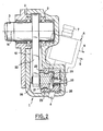
- the mechanism essentially comprises a hollow sector-shaped housing 1, in which revolves by means of bearings 2 an output shaft 3 typically intended to be coupled to a steering mechanism of the wheels d a motor vehicle, a force multiplier transmission comprising an input member 4 and an output member 5, and a fluid distributor 6 interposed between the transmission input member 4 and a control member 7 of the mechanism , typically connected to a steering wheel, by means of a dead-stroke coupling to selectively supply in outlet lines 8 and 9 a pressurized fluid conveyed to the respective working chambers of a fluid motor. assistance.
- the distributor 6 is a hydraulic distributor known per se, of the coaxial type with tubular rotor and bushing or of the star rotor type, itself providing the dead-stroke mechanical connection between the input control member 7 and the input member 4 of the transmission which in fact constitutes the outlet member of the distributor ' 6.
- the flat sector-shaped housing 1 defines an internal sector-shaped chamber 10 to which the working fluid outlet pipe 8 of the distributor 6 is connected.
- the housing 1 also comprises a radial arm 11 on which is hermetically fixed one end 12 of a curved tube 13 whose center of curvature coincides with the axis 14 of the shaft 3 and of the sector of the housing.
- the other end 15 of the curved tube is received in sealed fitting, by means of seals 16, in an opening 17 formed in the adjacent wall 18 of the housing 1.
- the curved cylinder cylinder constituted by the tube 13 moves in sealed sliding an annular piston 19 fixed by a screw 20 to a curved bar 21 having its center of curvature coincides with the axis 14 and forming the piston rod 19,
- the curved bar 21 extends all along the cylinder 13 to extend inside the chamber 10 of the housing 1, the interior end of the bar 21 being connected to one end of a swinging arm 22 made integral with the output shaft 3 and angularly struggling inside the sectoral chamber 10 of the housing 1.
- the distributor 6 is mounted on one of the faces of the housing 1 so that its longitudinal axis makes an acute angle with the general plane of movement of the swing arm 22 (as can be seen in Figure 2 ), the end of the input member 4 of the transmission swiveling in a bearing 25 formed in the housing 1.
- the toothed sector 23 is in the form of a conical toothed sector formed on the face of the curved bar 21 directed on the side of the distributor 6, the curved bar 21 being connected, by its opposite face, to the swing arm 22.
- the inner end of the curved bar 21 is hingedly connected to the outer end of the swing arm 22 by an axis element 26 received in a ' bore 27 of the curved bar 21.
- the curved bar 21 is guided, in its circular movement, by a curved guide 28 extending in the chamber 10 of the housing 1 and mounted on the side wall of the latter, the guide 28 comprising projecting projections 29 received in corresponding grooves of the curved bar 21.
- the guide 28 is mounted in an adjustable manner on the wall of the housing 1 by means of spring bolts 29, the springs 30 extending between an internal head of each bolt 29 and a shoulder 31 of the guide 28.
- the outer end 12 of the tube 13 is advantageously fixed to the arm 11 by a plug 31 into which the pipe 9 from the distributor 6 opens, the other pipe of the distributor 6 opening into the chamber 10 of the housing 1.
- the latter selectively sends pressurized fluid from a pressure source via one or other of the pipes 8 or 9 to the either of the chambers of the hydraulic motor formed by the piston 19 in the cylinder 13, namely on the side of the piston 19 directed towards the plug 31 or in the chamber 10 formed by the housing 1.
- FIG. 5 and 6 differs essentially from the embodiment described above in that the curved cylinder in which the piston 19 moves is formed by an extension 113 of the housing 1.
- the inner wall 114 of the cylinder 113 separating the latter of the internal chamber 10 of the housing 1 at the same time forms the bearing 25 for the input member 4 of the multiplying transmission, that is to say the rotating member output of the hydraulic distributor 6, similar to the previous but received, this time, in a bore 110 formed in a cylindrical portion 111 of the housing 1, the axis of the distributor 6 passing through the axis of rotation 14 of the output member 5 of the transmission.
- the curved bar 121 forming the piston rod 19 and provided with the toothed sector 23 cooperating advantageously with the pinion 24 of the input member 4 of the transmission, is formed in one piece with the pivoting arm 122 itself secured to the shaft - outlet 3 of the mechanism which revolves in the housing 1 by means of bearings 102.
- the guiding in its curvilinear movement of the curved bar 121 is performed locally, at the level of the engagement zone between the toothed sector 23 and the pinion 24, by a guide 123 mounted on the wall of the housing and comprising an arcuate groove 130 opening in the direction of the pinion 24 and receiving a projection 129 formed on the face of the curved bar 122 opposite the toothed sector 23.
- the cylinder chamber 113 opposite the internal chamber 10 is closed by a plug 31 to which the working fluid distribution pipe 9 of the distributor is connected.
- the other working fluid distribution pipe 8 supplying the internal chamber 10 of the housing 1, formed directly in the latter.
- the axis of the distributor 6, and therefore of the input member 4 of the transmission is parallel to the general plane of movement of the oscillating arm 122, the drive pinion 24 being conical.
Landscapes
- Engineering & Computer Science (AREA)
- Chemical & Material Sciences (AREA)
- Combustion & Propulsion (AREA)
- Transportation (AREA)
- Mechanical Engineering (AREA)
- Steering-Linkage Mechanisms And Four-Wheel Steering (AREA)
- Power Steering Mechanism (AREA)
- Actuator (AREA)
Applications Claiming Priority (2)
| Application Number | Priority Date | Filing Date | Title |
|---|---|---|---|
| ES506439A ES8302220A1 (es) | 1981-09-23 | 1981-09-23 | Perfeccionamientos en mecanismos accionadores con asistenciafluidodinamica |
| ES506439 | 1981-09-23 |
Publications (2)
| Publication Number | Publication Date |
|---|---|
| EP0075511A2 true EP0075511A2 (de) | 1983-03-30 |
| EP0075511A3 EP0075511A3 (de) | 1984-04-11 |
Family
ID=8483114
Family Applications (1)
| Application Number | Title | Priority Date | Filing Date |
|---|---|---|---|
| EP82401666A Withdrawn EP0075511A3 (de) | 1981-09-23 | 1982-09-14 | Antriebsmechanismus mit Fluidumhilfe, insbesondere für Servolenkungssystem |
Country Status (3)
| Country | Link |
|---|---|
| EP (1) | EP0075511A3 (de) |
| JP (1) | JPS58106206A (de) |
| ES (1) | ES8302220A1 (de) |
Cited By (3)
| Publication number | Priority date | Publication date | Assignee | Title |
|---|---|---|---|---|
| WO2007003000A1 (en) * | 2005-06-30 | 2007-01-11 | James Antony Kells | Toroidal ram actuator |
| WO2014184051A1 (de) * | 2013-05-16 | 2014-11-20 | Zf Lenksysteme Gmbh | Lenkgetriebe mit hydraulischer unterstützung mittels eines flügels |
| WO2014187664A1 (de) * | 2013-05-22 | 2014-11-27 | Zf Lenksysteme Gmbh | Lenkgetriebe mit hydraulischer unterstützung mittels eines drehkolbens |
Family Cites Families (4)
| Publication number | Priority date | Publication date | Assignee | Title |
|---|---|---|---|---|
| US2362930A (en) * | 1943-09-15 | 1944-11-14 | Mack Mfg Corp | Power assisted steering gear |
| DE2001721A1 (de) * | 1970-01-15 | 1971-07-22 | Adwest Eng Ltd | Lenkeinrichtung fuer Motorfahrzeuge |
| DE2931184C2 (de) * | 1979-08-01 | 1984-01-12 | Zahnradfabrik Friedrichshafen Ag, 7990 Friedrichshafen | Zahnstangen-Hydrolenkung |
| US4339986A (en) * | 1980-04-17 | 1982-07-20 | Trw Inc. | Power steering apparatus |
-
1981
- 1981-09-23 ES ES506439A patent/ES8302220A1/es not_active Expired
-
1982
- 1982-09-14 EP EP82401666A patent/EP0075511A3/de not_active Withdrawn
- 1982-09-22 JP JP57164186A patent/JPS58106206A/ja active Pending
Cited By (4)
| Publication number | Priority date | Publication date | Assignee | Title |
|---|---|---|---|---|
| WO2007003000A1 (en) * | 2005-06-30 | 2007-01-11 | James Antony Kells | Toroidal ram actuator |
| US7895935B2 (en) | 2005-06-30 | 2011-03-01 | James Antony Kells | Toroidal ram actuator |
| WO2014184051A1 (de) * | 2013-05-16 | 2014-11-20 | Zf Lenksysteme Gmbh | Lenkgetriebe mit hydraulischer unterstützung mittels eines flügels |
| WO2014187664A1 (de) * | 2013-05-22 | 2014-11-27 | Zf Lenksysteme Gmbh | Lenkgetriebe mit hydraulischer unterstützung mittels eines drehkolbens |
Also Published As
| Publication number | Publication date |
|---|---|
| ES8302220A1 (es) | 1983-03-01 |
| ES506439A0 (es) | 1983-01-01 |
| JPS58106206A (ja) | 1983-06-24 |
| EP0075511A3 (de) | 1984-04-11 |
Similar Documents
| Publication | Publication Date | Title |
|---|---|---|
| EP0072311B1 (de) | Hydraulischer Verteiler für Servomotor mit Zurückbringung in Ruhestellung | |
| EP1921325B1 (de) | Turbopropellertriebwerk, das einen Satz verstellbarer Propeller umfasst | |
| EP0066507B1 (de) | Hydraulischer Rotationsverteiler für eine hydraulische Antriebseinrichtung | |
| EP4185500B1 (de) | Getriebe und mit einem solchen getriebe ausgestattetes kraftfahrzeug | |
| EP0136234B1 (de) | Zahnstangen-Servolenkeinrichtung | |
| FR2814297A1 (fr) | Actionneur alimente electriquement, en particulier pour commander un composant de bicyclette | |
| EP1538067B1 (de) | Kraftfahrzeugachse und Stellglied für solche Achse | |
| EP0695398A1 (de) | Direkt angetriebener schieber | |
| EP0112249B1 (de) | Servolenkung für Fahrzeuge | |
| FR2641214A1 (fr) | Dispositif de cintrage de canalisations metalliques minces | |
| EP0130912B1 (de) | Schiefscheibentriebwerk, insbesondere für der Antrieb einer Pumpe | |
| FR2516465A1 (fr) | Engrenage de direction assistee | |
| EP0075519B1 (de) | Antriebsmechanismus mit Fluidhilfe, insbesondere für Kraftfahrzeugservolenkungssystem | |
| FR2715415A1 (fr) | Entraînement monté sur un dispositif de dépose pour le déplacement de tronçons de pont. | |
| EP0007861B1 (de) | Verstellvorrichtung für einen Rückblickspiegel, insbesondere für Fahrzeuge | |
| EP0331854B1 (de) | Druckmittelbetätigte Einrichtung für den Antrieb einer Drehwelle | |
| FR2653062A1 (fr) | Dispositif pour la deformation elastique d'une plaque d'impression fixee sur un cylindre porte-plaque. | |
| FR2503274A1 (fr) | Pompe alternative a course reglable, notamment pour la pulverisation agricole | |
| FR2654186A1 (fr) | Phare a faisceau orientable. | |
| EP0021950B1 (de) | Servolenkung für Kraftfahrzeug | |
| EP0254645A1 (de) | Servolenkungsvorrichtung für Kraftfahrzeuge vom Typ mit einem Servolenkungsventil | |
| FR2783451A1 (fr) | Robot de manipulation d'un objet | |
| FR2721576A1 (fr) | Direction à crémaillère assistée par un servomoteur. | |
| FR2570130A1 (fr) | Machine hydraulique a pistons radiaux | |
| EP1112681A2 (de) | Antrieb, insbesondere für einen Stalldungschieber |
Legal Events
| Date | Code | Title | Description |
|---|---|---|---|
| PUAI | Public reference made under article 153(3) epc to a published international application that has entered the european phase |
Free format text: ORIGINAL CODE: 0009012 |
|
| 17P | Request for examination filed |
Effective date: 19820922 |
|
| AK | Designated contracting states |
Designated state(s): DE FR GB IT |
|
| PUAL | Search report despatched |
Free format text: ORIGINAL CODE: 0009013 |
|
| AK | Designated contracting states |
Designated state(s): DE FR GB IT |
|
| STAA | Information on the status of an ep patent application or granted ep patent |
Free format text: STATUS: THE APPLICATION HAS BEEN WITHDRAWN |
|
| 18W | Application withdrawn |
Withdrawal date: 19840507 |
|
| RIN1 | Information on inventor provided before grant (corrected) |
Inventor name: BACARDIT, JUAN SIMON |